3. A Visual Guide to the Virtual Pinball Cabinet
Pinscape v2 Build Guide
A Visual Guide to the Virtual Pinball Cabinet
When I first started building my own pin cab, I found it hard to get a
handle on all of the pieces involved. I knew I wanted real flipper
buttons, but how do you connect them to the PC? I wanted a plunger,
but how the heck do you make a PC take input from a plunger? I wanted
feedback devices to simulate the flipper solenoids and replay knocker
and so on, and I understood that I needed an LedWiz for that, but
beyond that I didn't really know what it could do or how to
connect anything to it. And knowing how many questions I had,
I shuddered to think about the questions I didn't even know enough
to ask.
The diagram below will, I hope, clear up some of that fog, especially
the unknown unknowns. It's is a comprehensive map of all of the
electronic systems and devices that make up a virtual pinball machine.
It doesn't answer the detailed questions, like exactly how you hook up
the LedWiz or install software, but it offers a bird's-eye view of
everything that goes into one of these machines. It shows what each
component does and how everything fits together. The idea is to let
you see the whole system at a glance. This diagram shows pretty much
everything electronic in a pin cab, so you should be able to
quickly spot any major components that weren't already on your radar,
and decide if you need to add them to your plans.
This is a big-picture view, but it's also loaded with details that
you can view interactively. Roll over any component with the mouse
(or tap it) to learn more about it. There are also some general notes
following the diagram. But don't feel like you have to cram for
a quiz: we'll cover everything in the chart in much
greater depth in later sections.


Roll over/tap features to show details • See notes below
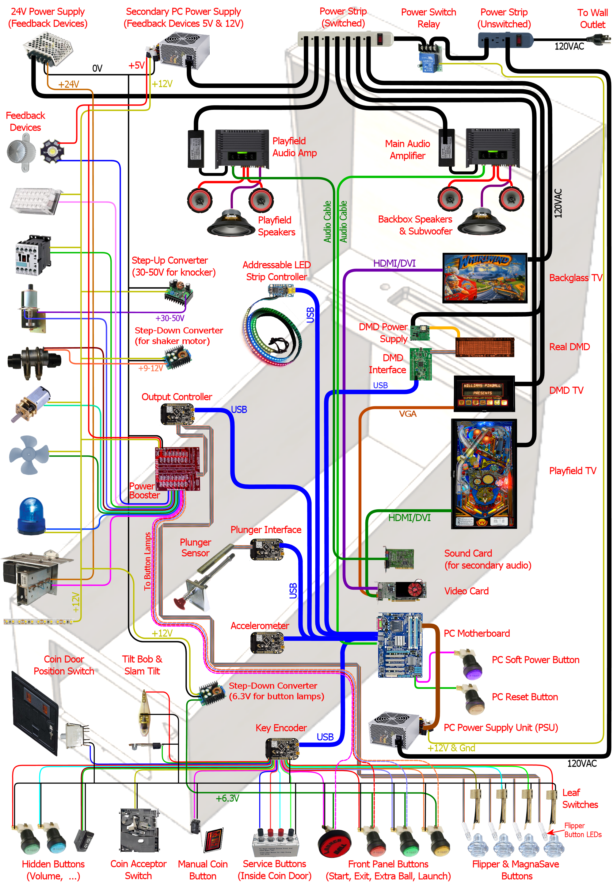
Feature Details
Notes
- The machine shown here is fully decked out. A bit more than fully, in fact: some things are redundant, such having both a "real DMD" and a "DMD TV". If you're in the planning stages for building a cab, you'll only need to consider the components related to the features you plan to include.
- This isn't a complete wiring diagram or schematic. For that, refer to the Build Guide sections on the individual subsystems.
- "DOF" (referred to several times in the detail popups) stands for DirectOutput Framework, one of the key pieces of software you'll want to install on the PC inside a cab. DOF is the software that handles the feedback devices.
How the Pinscape Controller fits in
You won't find any one box on the diagram that represents the Pinscape
Controller. That's because Pinscape is only one of several possible
choices for the functions it performs, and because Pinscape can perform
several different functions. So the diagram instead shows boxes for the
individual functions conceptually. If you do decide to use a Pinscape
Controller, it can fill any or all of these roles:
- Key encoder
- Accelerometer
- Plunger interface
- Output controller
The Pinscape Expansion Boards also serve as the "Power
Booster", which is shown as another separate box.
If you're using the stand-alone KL25Z without
the expansion boards, you'll need something to serve as
the power booster if you want to connect feedback devices. The Build
Guide includes circuit plans.
15,11-337,235 24V power supply
#num top: 40%;
A number of common feedback devices require 24V DC power. These
include the most common type of contactors used to simulate
flippers, slingshots, and bumpers, as well as real pinball
chime coils. If you're using any devices requiring 24V, it's
handy to have a dedicated 24V supply in the cabinet, since this
isn't one of the voltages you can get from the secondary PC power
supply. If you don't have any of the common 24V devices, there's
no need for this extra unit.
390,19-823,236 Secondary PC power supply
#num top: 40%;
This is a second PC-type power supply that isn't connect
to your PC at all, but is used to provide power to the feedback
devices and other devices in your cab. You actually don't need
to use a PC power supply per se here, since we're not using any
of its special PC capabilities but just using it as a source of
5V and 12V DC. But PC power supplies are great for this because
they're an extremely cheap way to get a good high-current source
of 5V and 12V power. The reason we care about having a 5V and 12V
supply is that these two voltage levels are exactly what's needed
for most of the common feedback devices. And for devices requiring
other voltage levels, we can usually use inexpensive step-up
and step-down converters that draw their power from the 5V or
12V lines.
9,426-229,571 RGB flashers
Real pinballs usually have a number of "flasher" lights (bright lamps
under plastic domes) around the playfield. These produce a brilliant
light that's a key part of the show. Emulated tables will of course
include the playfield flashers in the on-screen image, but a video
monitor can't approach the brightness of the real thing. For a better
simulation of the original light show, virtual cabs often include
real flashers, usually a set of 5 positioned inside the cabinet
just behind the back edge of the playfield TV, and/or on top of the backbox.
The flashers in virtual cabs usually use clear plastic domes rather than
colored domes, and use RGB LEDs as the lamps, so the software can
use them to display flashes in any color. High-power
RGB LEDs that produce very bright light can be found on eBay: look for
"3W star RGB LED".
Note that this type of LED usually requires a resistor for each color channel, to limit the electric current that flows through the LED element. The resistors aren't shown on the diagram, but the Build Guide section on wiring these devices has full details.
9,593-228,718 Strobe lights This is another popular lighting effect on virtual cabs. These are simply bright white lights. You can find the type most pin cab people use by searching eBay for "22 LED strobe". These are designed for use on cars and trucks, which means they run on 12VDC, which is perfect for a pin cab. 9,744-206,913 Contactors/solenoids The most basic "tactile" effect in a virtual cab is the thunk made by the flippers, slingshots, knockers, and the like. The best way to implement this is with something physically similar that actually goes thunk itself. Digitized sound from the speakers just doesn't have the same tonal quality or create the same sensation in your fingertips. One obvious approach is to use real pinball flipper and bumper assemblies, hidden inside the cab. Some cab builders do go that route, but these are expensive and take up a lot of space. A good compromise that many cab builders use is some kind of self-contained solenoid device. The most popular choice is the Siemens 3RH1140-1BB40 24VDC contactor, which is basically a beefy relay designed to switch high-power loads; it has a solenoid-driven switching mechanism inside that makes a decently pinball-like sound. Another popular option is automotive starter solenoids. Open-frame relays (easily found on eBay) can also serve. 44,913-180,1100 Replay knocker The replay knocker is such a distinctive feature of pinball machines that most virtual cab builders wouldn't dream of being without one. Digitized audio simply can't do justice to the hammer blast of a real knocker. Most cab builders opt for an authentic knocker coil assembly, which you can buy new from any pinball supplier. The real ones aren't very expensive, so hardly anyone bothers to look for a DIY alternative. 9,1105-216,1246 Shaker motor If you've ever played a real Earthshaker, or almost any recent Stern game, you've probably encountered a shaker motor in a real pinball. Shakers do what the name implies: they shake the machine (and the floor around it) like a minor earthquake is going on. This is one of the most dramatic feedback effects you can include in your machine, and it can really add excitement during play. The implementation is simple: it's just a DC motor with an off-balance weight attached. It's fairly straightforward and inexpensive to build one yourself. If you do include one, you'll get a lot of use out of it, because the standard DOF setup triggers it at well-chosen events in many tables, even those without shakers originally. 9,1246-195,1398 Gear motor Lots of real tables have something on the playfield that's controlled by a little electric motor, which you can hear when it's in action. These motors are usually linked with gears to the playfield features they control, and the gears are what make most of the noise. For a more realistic rendition of this distinctive sound, many cab builders like to include an actual geared motor in their cab. The software can activate this in sync with the game action, just like in the real game.Two main types of motor are popular among cab builders for this role. The first is the robotics motors available from many sellers on eBay: small DC motors with a couple of brass gears attached. They make about the right amount of noise, but some people think the quality of the noise is too "whiny". The other common type is auto windshield wiper motors. These are usually quieter and lower pitched than the robotics motors.
9,1399-194,1564 Fan A small handful of real pinballs featured fans on the backbox, most notably Whirlwind. Given the puny number of real machines with fans, you might wonder why you'd want one for a virtual cab. But then you'd be surprised at how many virtual cab builders include one. Like the shaker motor, the standard DOF setup triggers the fan on suitable events in lots of tables that didn't have one in real life, so you'll get a lot more use out of it than just playing Whirlwind and Twister. And like the shaker, it's a particularly tactile and dramatic effect that can be a lot of fun. Many cab builders use fans that are designed for automotive or boat use (since these conveniently run on 12VDC) and mount them on top of the backbox a la Whirlwind. Some cab builders have created sneaky hidden fan setups, with the fan inside the cab, blowing air at the player through an opening in the coin door or a vent under the machine. My own machine uses a replica of the Whirlwind fan with a custom enclosure designed to fit the theming of my cabinet art. 29,1599-189,1764 Beacons This is another popular light-show effect: a police-car rotating beacon light, or a pair of them, on top of the backbox. A surprising number of real machines had beacons; police themes are apparently as popular in pinball as on CBS. (In fact, F-14 Tomcat had three, and it wasn't even police-themed.) Like the shaker and fan, you'll get plenty of use out of beacons even in games that never had them originally. It's fairly easy to find suitably sized rotating lights of this sort on-line, especially from auto supply stores. A bonus is that anything designed for cars will conveniently run on 12VDC. There are also novelty beacon lights designed as party decorations, but those tend to be poor imitations. 3,1780-268,1986 Chimes & bells If you're a fan of classic electromechanical pinballs, you might consider installing some real chimes and/or bells. As with the knocker, recorded audio doesn't do justice to real percussion instruments. One option is to install an original pinball "chime unit" from the 1960s or 70s. These are basically little xylophones, with three or four metal bars and solenoid-driven hammers. The pinball manufacturers haven't made these in a long time, so if you want the real equipment from the EM era, your best bet is to find a salvaged unit on eBay. It might take some patience since there aren't all that many in circulation. There's also at least one modern reproduction unit available commercially (look for "McCullough's Chime Unit"), but reviews are mixed as to whether it sounds like the originals. The pinball suppliers don't sell full chime units, but they do sell many of the parts, so you might be able to cobble one together with a mix of original and improvised parts. Another option is to find some suitable "shell" type bells, which were used instead of chimes on many EM machines. You can use a regular knocker coil to strike them. Bells have their own distinctive sound, so a serious EM enthusiast might even want both bells and chimes, for more variety and authenticity in configuring different tables. Yet another possibility is an alarm-clock type of bell that strikes repeatedly when energized, since a few real pinballs had these (Taxi, Space Shuttle). Finally, a working decorative bell can also make a nice "topper" (something mounted on top of the backbox), as in the original Fire!. 4,2004-263,2049 LED strips/undercab lighting Many cab builders like to put RGB LED strips on the bottom of the cabinet or the back of the backbox. Look for "5050 LED strip" on eBay; these are adhesive-backed strips with LEDs spaced every couple of centimeters, designed for accent lighting. These strips only show one color at a time across the whole strip (unlike the "addressable" strips, which can show animated effects but require a special controller), so they're best for ambient lighting effects. This is a popular "mod" among real pinball owners, too. It creates a pool of light around the machine, adding to the overall show. 423,823-731,1050 Step-up converter for knocker #num top: 30%; Real pinball knockers in modern games are mostly designed to run on 50V. They'll work on lower voltages, but to get the proper amount of force for the knocker effect, you need at least 35V or so. There's nothing else in a typical virtual cab that needs that kind of voltage, so in all likelihood you'll end up needing a special power supply just for the knocker. A cheap and easy way to do this is to use a step-up voltage converter. These are available on eBay for about $15. These take 12V as input (which you can get from your secondary PC power supply), and let you dial in a higher voltage for the output up to some limit. Look for a converter that can go up to at least 35V, and preferably closer to 50V, and one that can supply about 5A at the highest output voltage. 430,1058-749,1209 Step-down converter for shaker motor #num top: 35%; If you build a custom shaker motor, you'll probably want to base it on a 12V DC motor, which means that you could power it directly from the 12V line from your secondary power supply. However, many people find that their shakers are too intense at full power, so they want to be able to turn down the power a bit. One easy way to do this is by dropping the voltage slightly with an adjustable step-down voltage converter. You can find these on eBay for a few dollars. These take 12V as input and produce an output voltage that you can adjust to any lower voltage. Connect the output to the motor, and adjust the output (by turning the control screw on the converter) to get the level of intensity you find most pleasing. 419,1271-719,1403 Output controller #num top: 20%; To control feedback devices, you need an output controller. This is a special device that you connect to the computer with a USB cable. The device takes software commands from the PC and translates them to electrical signals that turn your output devices on and off, in sync with the on-screen game action, to create feedback effects to enhance play. Almost any sort of electrical device can be used for feedback: lights, motors, solenoids, bells, chimes. Some controllers use relays to switch connected devices on and off (e.g., Sainsmart relay boards). Others use solid-state (transistor) circuitry (LedWiz, PacLed, Pinscape). Solid-state controllers almost always require some sort of "power booster" to connect anything more powerful than an LED or small lamp.$pinscapeLogo$The Pinscape Controller can serve as an output controller. If you use the stand-alone KL25Z, the number of outputs is limited: about 20 devices if you're also using it for any button inputs, or about 30 if not. The plain KL25Z also requires power booster circuits to power anything, even small LEDs. With the expansion boards, the number of outputs is practically unlimited, plus the power boosters are built in, so you can connect powerful devices like solenoids and motors directly.
419,1445-703,1643 Output power booster If your output controller has solid-state (transistor) outputs, you'll probably need some kind of power booster to connect anything beyond LEDs and small lamps. The LedWiz and PacLed devices both have this requirement, as does the stand-alone KL25Z with the Pinscape software.There are several ad hoc solutions that work with any controller. One is to use relays; that's a simple solution, but has some drawbacks. Another is to use the common "LED amplifiers" sold on eBay. These work for high-current LEDs but might not be suitable for solenoids and motors. For a more robust solution, you can use a booster designed specifically for your controller. Zeb's Boards sells specially designed booster boards for the LedWiz and PacLed devices. That's a more expensive option, but easy to set up and superior to the ad hoc solutions.
$pinscapeLogo$If you're using the Pinscape Controller with the expansion boards, you won't need any other boosters, because the expansion boards have powerful booster circuits built in. If you're using the stand-alone KL25Z, you can use one of the ad hoc solutions (relays, LED amplifiers), or you can build your own inexpensive solid-state booster circuits using a simple circuit design detailed in the Build Guide.
784,839-1056,1191 Addressable LED strips #num top: 25%; An addressable LED strip is an adhesive-backed strip about a centimeter wide with a row of small LEDs down its length. "Addressable" means that each LED on the strip can be controlled independently, for animated lighting effects. This is still a relatively new and rare "toy" in virtual pin cabs. Some cab builders place these strips along each side of the playfield TV, where the addressable lights can be tied to flashing lights and other events on the playfield.A special controller device is required to connect this type of light strip to the PC, typically by USB. Free open-source firmware is available that turns a Teensy 3.1 (an inexpensive Ardunio-type USB device) into an addressable strip controller that works with Visual Pinball.
735,1705-1003,1853 Plunger interface #num left: auto; right: 0px; top: 15%; This is a USB device that connects the plunger sensor to the PC. Several options are available, including commercial products from Zeb's Boards and VirtuaPin. Many of the available plunger devices also include accelerometers for nudge sensing, and some also include key encoders for button input. Plunger input is sent to the PC as joystick input, since that's the format that Visual Pinball and other emulators use to read the data.$pinscapeLogo$This is one of the roles the Pinscape Controller can fill. In fact, plunger sensing was the whole project's original purpose.
548,1746-735,1988 Plunger sensor #num top: 25%; To connect a standard pinball plunger to the PC, you need some kind of sensor that reads the position of the physical plunger and converts it into an electrical signal. There are many approaches. The Pinscape Controller can use an optical sensor that essentially takes rapid pictures of the plunger and finds the position by scanning the images; it can also work with a potentiometer that's mechanically linked to the plunger, using the varying electrical resistance of the pot to determine the position. The Zeb's Boards kit uses a quadrature sensor, which senses the motion by counting pulses in a moving magnetic bar code. The VirtuaPin kit uses an IR proximity sensor, which uses the brightness of infrared light reflected from the tip of the plunger to estimate the distance from sensor to tip. The type of sensor you use will depend primarily on which controller you choose; if you go with a commercial kit, it will include the sensor.Note that virtually all of the sensor options are designed to work with a standard pinball plunger assembly. The commercial kits usually include the plunger. For Pinscape or other DIY options, you can get the plunger assembly from any pinball parts supplier.
748,2018-973,2134 Accelerometer #num top: 25%; Nudging is such an integral and unconscious part of real pinball play that good emulation demands a way to sense when you nudge, shake, or shove the cabinet. The best way to do this is with an accelerometer. A good one can tell the difference between a slight nudge and a hard shove, allowing the simulation to react proportionally.Visual Pinball and other pinball emulators have good support for accelerometer-based nudging. They take accelerometer input via the standard USB joystick interface, so you just need a device that reports acceleration data this way.
$pinscapeLogo$The Pinscape Controller can fill this role (and the accelerometer on the KL25Z is very good). Most of the commercial plunger kits also include a nudge feature, so you probably won't need a separate accelerometer if you have any sort of plunger device. If you decide not to install a plunger, you can install a Pinscape Controller or one of the other plunger kits for its accelerometer features alone if you wish.
960,15-1301,158 Switched power strip This is a second power strip that provides line power to all of the secondary devices in your system: the TVs, the audio amplifiers, and the feedback devices. The line power coming into this strip is controlled by the power switch relay, so the strip receives power when the PC is turned on and is effectively "unplugged" when the PC is off. This provides nice integration for all of the systems in your cabinet so that you can control everything with the main PC soft power button.An alternative to using the switching relay and a second power strip here is to combine everything into one "smart" power strip designed for computers. A smart strip has a "master" outlet that plugs into the PC, and controls the other outlets according to whether the PC is turned on or off. This is simpler to set up than using a separate relay, but some people have trouble getting these to work reliably. Some motherboards don't seem to draw enough power to trigger the "smart" switching function on some of these strips.
1286,17-1526,247 Power switch relay #num top: 50%; This lets the PC control power to all of the secondary systems in your cabinet: the TVs, the audio amplifiers, and the feedback devices. This works as follows: when the PC is turned on, the 12V power supply from the PC turns on, which activates this relay, supplying power to the second "switched" power strip. When the PC is off, the 12V line turns off, which turns off the relay, which cuts power to the second power strip. This effectively "unplugs" all of the devices on the second power strip. You'll want to choose a relay specifically designed for switching high-power loads. The type designed for air conditioners and water heaters is perfect. Because of the high voltage going through the relay terminals, you'll want to be sure to thoroughly enclose this relay in a protective plastic box so that you don't ever accidentally touch any exposed wires, and so that nothing shaking loose in the cabinet can ever come into contact with the wires.An alternative to the power switch relay is to use a "smart" power strip designed for computer use. Smart power strips do the same thing as the relay, but this action is built in to the strip, so you don't have to buy extra parts or do any wiring. Smart power strips are more expensive, though, and some cab builders have had problems with their sensitivity. Smart strips are triggered by the amount of power being drawn through the "master" outlet connected to the PC, so if your PC doesn't draw enough power, it might not trigger the smart strip to turn on the other outlets. An external relay doesn't have this problem because it's triggered by PC power supply voltage output rather than its current input, which makes the relay approach work on every PC. Smart strips can also be perfectly reliable, but this depends on the combination of PC and smart strip model you choose.
1536,17-1774,161 Main power strip #num top: 50%; For the PC power supply connection, you'll want a simple power strip that's left plugged in all the time. This lets you control power to the PC with the "soft" power button. Most people use a power strip with a built-in surge suppressor to protect the PC from power spikes in your house wiring and utility service. For a neat, integrated look to your cabinet, mount this inside the cabinet, and run its power cord out through a hole, to serve as the main power cord that you plug into the wall outlet.Note that most power strips have a built-in manual switch to turn power to the outlets on and off. Even though we're calling this the "unswitched" power strip, it's perfectly okay to use a power strip with one of these manual switches. You'll just ignore that switch and leave it on all the time.
593,336-1045,571 Playfield audio amplifier This is a secondary audio amplifier, connected to your extra sound card. This is an optional system; most cab builders don't bother with it. If you choose to use it, this is simply another amplifier like the one powering your main speakers. This one connects to the second sound card in the PC and to the playfield effects speakers, usually positioned inside the cabinet under the playfield TV. The purpose of this second set of speakers is to audibly place the table sounds effects closer to their simulated sources. The table sounds are things like the ball rolling around and bumping into things, the flippers, the bumpers, and so on - sounds that in the real game would be coming from the playfield area.One alternative to a separate playfield audio amp is to use the speakers built in to your playfield TV. Many flat panel speakers are too small and tinny for this to sound any good, though. Another alternative is to use a multi-channel amp for the main audio amplifier, with enough independent channels to drive the main speakers and the playfield speakers.
594,575-983,792 Playfield speakers #num top: 50%; This is an optional, secondary set of speakers dedicated to reproducing the playfield sound effects, such as the ball rolling around and bumping into things, the bumpers, the flippers, etc. These speakers should be placed inside the main cabinet, under the playfield. Visual Pinball doesn't currently do anything to position these sound effects spatially, so a single speaker is all you really need here. However, you'll probably want a stereo pair anyway to help spread out the sound so that it doesn't sound like it's all coming from a single point on the playfield. You can also use a separate subwoofer for this set of outputs. Some people use "tactile" subwoofers here - the type that video gamers and home theater enthusiasts attach to their chairs to create a Sensurround® effect. A tactile subwoofer can let you feel the ball rolling and bumping effects through the cabinet, which can add to the realism, although you might find that you have to edit some tables to tone down their effects. Some are too much of a good thing with a tactile sub.An alternative to using separate speakers here is to play these effects through your playfield TV's built-in speakers. Flat panel TV speakers are often too small and tinny for this to sound any good, though; many table effects need good bass reproduction to sound right.
1247,404-1705,556 Main audio amplifier #num left: -4ex; top: 50%; The audio amplifier for your main speakers. This connects to your PC's audio output - the "line out" jack on your motherboard, if it has one, or on your main sound card - with a standard audio cable. Many types of amplifiers can be used here. Many people use car amps, since they're compact and run on 12V, which means they can be powered from a PC power supply. Another popular option is to use powered computer speakers. You could even use a home-audio receiver or amplifier, although these tend to be too bulky to easily fit in a pin cab. If you use a subwoofer, you'll want at least a "2.1" channel amp - two stereo channels plus a mono subwoofer channel. Some 4-channel car amps can be wired with one pair of channels "bridged" together to serve as the subwoofer channel. 1211,580-1720,776 Main speakers and subwoofer #num left: 25%; top: 5%; If you're building your cab in the style of the real machines from the 1980s and 90s, the main speakers will consist of a pair of small (4" to 5") "satellite" style speakers mounted behind the speaker panel in the backbox, and a separate large (8" to 10") subwoofer mounted on the floor of the main cabinet, facing down through a circular opening. Cab builders often use car speakers for these, since many good options are available in the right size range. If you're building your cab in the style of an older machine from the electromechanical era, you'll have to be more creative about where to put the speakers, since the "sound systems" on those machines consisted of actual noisemakers (chimes and bells), not speakers. 1440,821-1972,989 Backglass TV This is a TV positioned where the translite or backglass would normally go in a real pinball. This is connected to the PC video card with HDMI or DVI like an ordinary PC monitor, and Windows sees it as a second display. If you haven't done this before, it's easier than it sounds, because Windows has built-in support for multiple displays that actually works pretty effortlessly. Visual Pinball and other emulators can easily be set up to display the animated backglass graphics on this separate monitor for realistic play.If you build your cab following the 1990s style, with a separate speaker/DMD panel, most 30" widescreen (16:9) TVs will be a good fit. They're almost exactly the right width, but they're not quite tall enough, so there will be about a 1" gap above and below. You can cover the gap with a painted or decal mask on the translite.
Some cab builders opt for a single monitor filling the whole backbox area rather than using a separate speaker panel. That arrangement is even tricker because the backbox has a nearly square aspect ratio, and square TVs simply don't exist. The usual solution is to use a widescreen monitor in portrait mode, and submerge part of into the cabinet below the backbox. This has disadvantages, obviously.
1200,839-1378,874 Backglass TV video cable The backglass TV connects to the PC video card with an ordinary video cable, usually HDMI on the TV side, and either HDMI or DVI-D on the PC side. 1482,1095-1951,1165 Real DMD Most real pinballs from the 1990s and later used Dot Matrix Displays, or DMDs, positioned in the speaker panel at the bottom of the backbox. The real DMDs from the 90s were mostly 128x32 plasma displays; these are extremely bright and have a distinctive amber color. Recent Stern games have switched to LED displays with the same pixel layout, and still in monochrome, but with different colors on different games. Visual Pinball and some other emulators can take advantage of the authentic equipment, either plasma or LED, to display animated graphics just like the real machines. You can't get more authentic for the games that had DMDs originally. For a modern variation, full-color RGB LED panels are now available with the same pixel layout, allowing more variations than the traditional monochrome. A slight drawback to real DMDs is that their low resolution makes them less flexible for games from the pre-DMD era, such as the alphanumeric games. Another complication is that you'll need some extra hardware: namely, a DMD interface board to connect it to the PC, and in the case of a plasma DMD, a special power supply. 1170,1050-1442,1125 Power supply for real DMD #num left: -10%; If you're using a plasma Dot Matrix Display (DMD), you'll need a special power supply module just for the display, since the plasma panels require high voltages that you can't get from a regular PC power supply. Suitable power supplies are available commercially, or you can build one yourself if you're good with electronics. Most LED DMDs run on 5V, meaning they don't need separate power supplies but can use the regular PC PSU. 1170,1131-1442,1240 DMD interface module #num left: -10%; If you're using a Dot Matrix Display (DMD), you'll need a special device to connect the DMD to the PC. This applies to both the plasma and LED panels. DMD panels won't work directly with a PC, as they don't have any of the necessary electronics on board to connect to a regular video source. Fortunately, there are special interface modules available that bridge this gap. These connect to the PC via USB cable, and translate the PC software commands to the electronic signals that control the DMD. One option is a commercial product called PinDMD (available in verions, PinDMD2 and PinDMD3). Another option is an open-source DIY project with the confusingly similar name Pin2DMD. 1479,1221-1951,1344 DMD TV Most real pinballs from the 1980s and 90s had score displays positioned in the speaker panel the bottom of the backbox. The early versions of these panels used 14-segment alphanumeric displays. More modern games changed to Dot Matrix Displays (DMDs), which can display full graphics, albeit at fairly low resolution (usually 128x32 pixels). One way to simulate both types of display is to use a small TV or a laptop LCD panel, positioned in the speaker panel where the DMD would go in a modern machine. Like the playfield and backbox TVs, this is just another video monitor as far as Windows is concerned. Visual Pinball and other pinball programs can take advantage of it show the DMD graphics or alphanumeric score. A 15" laptop screen is almost exactly the right width for the standard DMD size of real pinballs; it's taller than the real thing, but you can hide the excess height behind the speaker panel. An alternative is to use a real pinball DMD. Another is to leave this out entirely, and overlay the DMD area onto the bottom of the main backglass TV. 1286,1332-1395,1361 DMD monitor video cable If you use a TV or video monitor for the DMD area, this connects to the PC video card with an ordinary video cable. This is usually VGA for a third monitor, for the simple practical reason that most video cards don't have three HDMI/DVI ports but do usually have a spare VGA port left over even after connecting two other monitors. 1471,1363-1951,1725 Playfield TV #num left: -3ex; A large TV or monitor goes where the main playfield sits in a real pinball. You connect this to the PC video card with an ordinary video cable, and Windows simply sees the TV as a monitor. A regular 16:9 widescreen TV is a pretty good approximation to the aspect ratio of a real playfield when rotated 90° (for "portrait mode"). You can either choose a TV that fits your cabinet, or build a custom cabinet around your TV. Before deciding, you should be aware that all of the pinball cabinet hardware you can buy off-the-shelf is designed to fit just two size options, known as "standard body" and "widebody". If you build a cabinet with custom dimensions, you'll need custom versions of some of the accessory hardware. The standard body is 20.5" wide on the inside, which is enough to fit most 39" TVs and some 40". The widebodies are 23.25" wide on the inside, which will fit up to about a 45" TV. In terms of the displayed image size, a 39" TV yields about the closest match to the true object sizes; the image on a larger TV in a widebody is a bit larger than life. Many people use widebody plans anyway, for the greater flexibility in choosing a TV, and also because larger-than-life can also be fun. 1244,1668-1432,1700 Playfield TV video cable The playfield TV connects to the PC video card with an ordinary video cable, usually HDMI on the TV side, and either HDMI or DVI-D on the PC side. 1237,1772-1764,1867 Sound card for secondary audio #num left: -10%; Visual Pinball can take advantage of two separate audio systems. The first is used to play back the original "soundtrack" of the game (the music, speech, and sound effects that played through the backbox speakers on the original arcade machine). The second system plays the "table" sound effects, such as the sound of the ball rolling around the field and hitting things, and the sounds made by the bumpers, flippers, and other solenoids. It makes the simulation a little more realistic to play the table effects from speakers inside the cabinet, under the main TV, closer to where they'd come from in a real machine. To take full advantage of VP's ability to separate the sound effects, you have to add a separate sound card. Most modern motherboards have a "sound card" built in, so all you need is one add-in sound card to get the second set of channels. This might sound like it's asking for trouble with Windows device conflicts, but it's actually no problem, as Windows has good support for using multiple sound cards. Connect your backbox speakers to the primary audio output (usually the one on your motherboard), and connect your in-cabinet "table effects" speakers to the extra audio card. The second sound card is completely optional, as VP will play everything through a single set of speakers by default, but the extra spatial separation from a second set of speakers is a nice little enhancement. 1214,1889-1618,1963 Video (graphics) card #num left: -10%; Pinball emulators are fundamentally video games, so a good video card is important. Video pinball doesn't lean on the graphics processor quite as heavily as the most demanding 3D games, so you don't need a super high-end gaming rig, but you'll definitely want something more powerful than a basic business-graphics card. Look for a good mid-range gaming card. An important feature to consider is support for multiple monitors. If you plan a 3-monitor setup (playfield, backglass, DMD), be sure your card has at least three outputs, with a set of connectors compatible with your monitors. The reason that multiple-monitor support is important is that most people find that you get much better performance by connecting all monitors to one video card than splitting monitors across cards. 1223,1990-1382,2211 PC motherboard #num left: -33%; The heart of a virtual pinball machine is a standard PC motherboard running Windows. 1473,2106-1906,2220 PC soft power button #num left: -5%; Standard PC motherboards have wiring for connecting a "soft" power button - push the button to turn the PC on, push it again to tell Windows to power down. The button wiring can be connected to any ordinary momentary pushbutton switch. The type of button commonly used for a real pinball machine's front-panel Start button is a good choice, because it's easy to install in cabinet and has an integrated microswitch that's easy to wire. On real pinball machines, it's standard to place a "hard" on/off switch (which physically connects and disconnects line power) on the bottom of the cabinet, near the right edge and a few inches back from the front. This is nicely hidden away but easy to reach and easy to find by feel. For a virtual machine, I recommend placing the "soft" power button in the same spot. 1473,2221-1834,2334 PC reset button #num left: -5%; Most PC motherboards have wiring for connecting a reset button, to forcibly reboot the system in case the operating system crashes. This can be connected to a simple pushbutton switch, such as the type used for the soft power button or the front-panel Start button; one possibility is to place this on the bottom of the cabinet near the power button. Or you can connect this to something akin to the "service buttons" inside the coin door. For modern Windows systems, this type of button isn't all that useful, but some people like to include one just in case. 1193,2297-1470,2453 PC power supply An ordinary PC power supply unit (PSU) is needed to power the motherboard. This should be connected to an unswitched power inlet, since the PC should always be physically plugged in to wall power to allow turning it on with the soft power switch. I recommend powering only the PC components with this PSU, and using separate power supplies for the feedback devices. 823,2350-1019,2481 Key encoder #num top: 15%; left: -3ex; This is a core device that almost every virtual pinball machine needs. It lets you to connect real pinball buttons (flipper buttons, Start buttons, etc) to the PC. Most of these devices connect via USB, while some connect to a PS/2 keyboard port. Depending on the device, the physical buttons in your cabinet are mapped either to keyboard input on the PC or joystick button input. Some key encoders let you program which keyboard keys or joystick buttons are sent to the PC, and some have pre-set mappings that you can't change.$pinscapeLogo$The Pinscape Controller can fill this role. It lets you map buttons to keyboard keys or joystick buttons of your choosing (or a mix of the two), and lets you program all of the mappings individually. Pinscape also lets you assign a "Shift" button that gives every other button a secondary assignment, letting you access more functions without adding more physical buttons. There are also commercial key encoder devices available that offer similar features, including the i-Pac and KeyWiz. Or, if you buy one of the commercial plunger kits, it will probably provide button input as a bonus feature, although it'll have a limited number of inputs and probably won't let you choose your own key mappings.
630,2206-1069,2305 6.3V step-down converter #num top: -3ex; The most common type of illuminated pushbutton for the front panel of your machine (e.g., the Start button) uses #555 light bulbs. These bulbs are designed to run on 6.3V, which is a rather odd voltage that you won't find anywhere in a PC. These bulbs will also work on 5V (available from the PC power supply), but they'll look a little dim at the reduced voltage. If you don't like that, one solution is to replace your incandescent #555 bulbs with LED equivalents, most of which will work on 5V without loss of brightness. Another solution is to keep the incandescent bulbs and supply them with the right voltage, by using an adjustable step-down voltage converter, which can be found on eBay for a few dollars. What these do is take a power supply voltage on their input terminal, say 12V, and let you select a lower voltage on the output terminal by turning a dial. Get one of these and set it to 6.3V for your illuminated buttons. A single converter can supply power to multiple buttons. 25,2125-338,2476 Coin door position switch Real pinball machines have a switch that senses when the coin door is open. This is usually implemented with a plunger switch that's pushed in by a bracket when the coin door is closed, and released when the door is open. You can get the authentic type of switch from pinball suppliers. You can also use a regular microswitch, although it's a little harder to get the mounting geometry right with such a small switch. You can also just install a manual "coin door" button, which is simpler to set up but a little less convenient to use, obviously. In any case, it's useful to have something to serve this role, since many tables won't let you access the service menu unless they think the door is open, which requires that they get the appropriate switch signal. Whatever type of control you choose for this, you can connect it to the key encoder like your other buttons. 381,2123-560,2461 Tilt bob & slam tilt #num top: 25%; If you have an accelerometer, you'll probably also want a real tilt bob. This is a really simple device that consists of a freely hanging metal weight surrounded by a metal ring. When the weight touches the ring, it makes electrical contact and acts like a switch. Shaking the machine makes the weight swing; shaking too much makes it swing far enough to touch the ring. The pinball software can simulate this at a simplistic level using the accelerometer data, but real cabinet motion is complex enough that the simulation isn't usually very convincing. A real tilt bob works better, and it's cheap enough and easy enough to set up that I think every cab with an accelerometer should have one. Just wire it to the key encoder like a button.There's another type of tilt detector called a "slam tilt". It's usually built in to real coin doors. It looks like an oversized leaf switch with a big metal weight at the end of one leaf. This detects hard shoves on the front of the cabinet, mostly to deter arcade customers from seriously abusing the equipment or trying to break into the coin box. It's not very important in a virtual machine because you're probably going to treat it more kindly anyway. But if you're a completist, you can connect this to the key encoder like your other switches. As with other coin door items, it will probably be wired to the coin door wiring harness.
26,2649-323,2876 Hidden buttons Some cabinet builders like to add a few extra buttons that aren't part of a real pinball, but serve some special "virtual" function. And because the buttons aren't authentic, many builders like to put such buttons somewhere out of plain sight, so as not to affect the aesthetics. One good hidden location is the bottom of the cabinet, near the front edge, where buttons can be easily reached and identified by feel. This is good for buttons you might want to access frequently, like a volume control or a manual "Coin In" button. Another option is to hide buttons inside the cabinet, close to the coin door or even mounted on the coin door itself. This option is best for buttons that you'll access infrequently or that you don't want curious guests messing around with, like a manual "coin door" button or service menu buttons. 338,2621-555,2876 Coin acceptor switch If you have a real coin door, and you choose to install real coin acceptors (often called "coin mechansims" or just "mechs"), you can set up your machine so that feeding in a quarter sends a coin signal to Visual Pinball. This is actually pretty easy, because the coin mechs use a simple microswitch that's tripped by the passage of a coin through the acceptor slot. So all you have to do is wire the switch to your key encoder. The slight complication (as with the coin door service buttons) is that the coin switches are usually wired to a connector or wire harness along with all of the other coin door wires, so you might have to spend a little time sleuthing out which wires connect to the coin switches. Once you do, just connect them to the key encoder. Note that if you also have a manual "Coin In" button, you can simplify things by wiring the coin acceptor switch and Coin In button in parallel, so that either one can be used to add a coin in the simulation. 570,2660-751,2876 Manual coin button It's handy to have a dedicated button somewhere on your machine to simulate inserting a coin. You won't need it very often, because it's fairly easy to set most games to Free Play mode where coins aren't needed. Some older games are difficult or impossible to set to Free Play, though; the easiest way to handle them is to feed them fake coins with a button. Some cab builders just add a Coin button to the front panel, alongside the Start and Exit buttons. Others hide a button under the bottom of the cabinet or inside the coin door. My favorite solution is to use the Coin Reject buttons on the coin chutes, assuming you have a standard coin door. You can position microswitches behind these buttons so that pushing one triggers a switch. Whatever placement you choose, you can simply wire this button to your key encoder like the rest. 770,2660-1019,2876 Service buttons Real pinball machines from the 1980s onward have a set of "service" buttons inside the coin door. These let the operator access the machine's setup menus for adjusting game options, pricing, etc. The same buttons are useful in your virtual machine because they let you make the same types of adjustments to the virtual tables you play.If you have a real coin door on your machine, it'll come with the standard set of service buttons for its vintage (older machines usually had three buttons, newer machines usually have four). You can wire these to your key encoder just like all of the other buttons. The only complication is that your real coin door will probably be pre-wired to some kind of wiring harness or connector, so you'll have to figure out what each connector terminal is wired to. An alternative to using the genuine coin door service buttons is to install some extra buttons of your own, probably placed out of sight somewhere (see "hidden buttons").
1020,2660-1484,2876 Front panel buttons Most virtual pinball machine builders include the most common buttons that real machines have. The only one that's truly universal is the Start button, but enough machines from the 1990s also had an "Extra Ball" button (sometimes called "Buy In" or something else) that many virtual cabs include one. A "Launch Ball" button is also useful, as a fair number of 1990s pinballs had buttons in lieu of plungers. Some cab builders even dispense with the plunger entirely and use only a Launch button, since plungers are more expensive and more complicated to set up than buttons.Some cab builders add one or more buttons on top of the lockdown bar (the bar at the front that holds the top glass in place), replicating the "Fire" button found on many recent Stern games. A handful of older games had one or more extra buttons here as well. These are trickier to install than front-panel buttons because they need holes in the lock bar.
Virtual pin cabs need at least one extra button that real games lack: an "Exit" or "Menu" button, to exit the current table and return to the game picker menu. Some cab builders add other special-purpose buttons for other game picker functions, such as "Instructions" or "Flyer"; others prefer to keep the front panel buttons to a minimum, to be more like real machines. A "Coin In" button can also be handy, although this can be handled more elegantly by using the Coin Reject button on the coin chute.
The best choice for most of the front panel buttons is the "button & lamp assembly" that you can find from pinball and arcade suppliers. These have everything in one nicely integrated package: pushbutton, trim, microswitch, and lamp. They easily mount on the panel face through a round drill hole, and can optionally be set flush with the panel by routing a recess. ("Launch Ball" buttons have a larger button face, but these are available in the same type of combined assembly.) The buttons have four terminals on the back: two for the switch, and two for the lamp. Connect the switch terminals to your key encoder, and connect the lamp terminals to your output controller. The output controller can then turn the button light on at appropriate times in the game.
1496,2518-1968,2867 Flipper buttons If there's a single must-have feature for a virtual pinball machine, this would be it. There's a certain feel unique to real flipper buttons, which makes them essential to proper emulation. You can order standard flipper buttons from a pinball supplier, along with leaf switches. The leaf switches connect to your Key Encoder the same way as any other switch.Most cab builders install two sets of flipper buttons on each side of the cabinet. The second set is optional, but I'd recommend them. The front set, as you'd expect, is for the flippers. The rear set, located just behind these, is used for other functions that vary by table. Everyone calls these "Magna Save" buttons, because that's the most widely known feature on real machines that used extra buttons like these. But it's a bit of a misnomer, since most of the tables that had extra buttons like these used them for different purposes entirely. There are enough tables that take advantage of extra buttons that most cab builders think it's worthwhile to include them.
Starting in the mid 1990s, the real pinball manufacturers began moving from leaf switches to optical-interruptor switches. You can use optical switches in a virtual cab if you wish, although they're more expensive, and they don't feel exactly the same. The main reason they moved to optical switches on real machines is that they stand up better to heavy arcade use than leaf switches. That's less of a concern with home use, so most cab builders go with the cheaper and simpler leaf switches.
Flipper buttons are available in numerous colors, so you can choose something that coordinates with your cabinet artwork. Or, for a cool lighting effect, use clear buttons, and place a pair of small RGB LEDs behind each one. Connect the LEDs to your output controller. The pinball software will then be able to light up your flipper buttons in the same color originally used on the real machine whenever you load a table.
