24. Backbox Hardware Installation
This section continues with the cabinet trim hardware, moving on now to
the backbox.
We assume that you've already built the wood shell of the backbox as
described in Cabinet Body, and that you've already painted it
and/or applied decals, as described in Cabinet Art. It's best
to finish the artwork before installing any hardware, since some the
hardware will get in the way of painting or applying decals once
installed.
As with the Cabinet Hardware Installation chapter, we try to present things
in an order you can follow for installation.
Translite lock
The real machines have a keyed lock at the top of the backbox that
secures the translite, so that arcade customers can't steal the
translite or get into the backbox to mess with the electronics.
The operating principle is pretty simple. In the locked position, a
metal tab on the lock sticks into the slot at the top of the backbox
trim that the translite fits into. This prevents lifting the
translite, which is necessary to remove it.
In the unlocked position, the metal tab swings out of the way, letting
you lift the translite into the slot, which in turn lets you remove it.
With the lock open, there's enough play that you can remove the
translite, as described below.
With the lock closed, the tab prevents moving the translite far enough
to free it from the top and bottom trim channels, so it's effectively
locked in place.
The translite lock is purely for the sake of security - it's there to
prevent anyone without the key from removing the glass. The glass
won't fall out on its own, though, even if you don't install the lock
- it's held in place by the slots it sits in, and you have to
intentionally maneuver it out of the slots to remove it. So it's not
a functional necessity in a home setting, unless you have obnoxious
friends. (The exception is that the glass could conceivably come
loose during transport if you give it a bumpy enough ride. A lock
does help prevent this by ensuring that the glass can't move out of
its slots.)
Installing the translite lock
First, assemble the pieces of the lock plate. Slip the lock through
the hole in the plate, slip the hex nut over the back of the lock,
and tighten the nut.
It should look like this when assembled.
The pinball vendors sell the lock plate assembly as a complete kit,
which includes a pair #8-32 machine screws with security Torx heads.
There are two reasons you might want to discard these and substitute
your own wood screws. The first is that they're the security Torx
type, so you need the special security type of Torx driver to use
them. "Security screwdriver" is a bit hyperbolic when anyone can go
buy one at Home Depot, but it's at least a slight deterrent against
mischief simply because most people don't have one lying around. The
second reason you might be inclined to discard the special screws is
that they're machine screws, not wood screws. They won't attach well
to plain wood. They require T-nuts, which must be pre-installed
behind the trim, as explained in "Translite lock plate preparation" in
Cabinet Body. If you skipped that step
when installing the trim, it's probably too late. Fortunately, wood
screws are a pretty decent alternative, especially if you're not
concerned about the security aspect of the lock. And if you are
concerned about that, you could substitute tamper-resistant wood
screws.
Before installing the lock plate, use a key to check the orientation
of the lock. Turn the lock so that it's in the extended position,
with the lock tab sticking up perpendicular to the plate. Be
sure to install it with the tab facing the back of the backbox.
If you did already install T-nuts for the Torx screws, simply put the
lock plate in position, and fasten it with the Torx screws.
If you didn't install the T-nuts, discard the Torx screws that came
with the kit, and substitute a pair of wood screws. I'd go with #6 x
¾". Rounded-head screws will look better, as will black screws
if you can find them (if not, you can just paint the heads black after
installation if you want).
Line up the lock plate over the gap in the top trim. It should be
centered over the gap, which should be the same as centering it
side-to-side overall in the backbox. Mark the positions of the screw
holes. Remove the plate and drill pilot holes for the #6 screws. Put
the lock plate in position again and fasten the screws.
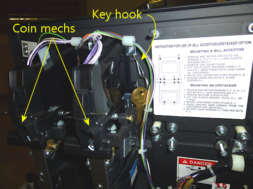
Where to keep the keys
With the real machines, the standard way to keep track of your
translite keys is to keep them on a little hook inside the coin door.
The WPC and SuzoHapp doors provide a hook specifically for this
purpose, located next to the coin mechs.
If you're not installing a standard coin door or can't find the key
hook, you might put a little eyelet or hook on the inside wall of the
cab somewhere convenient, and hang the keys there.
DIY alternatives
If you don't need the locking function, but your backbox has the gap
in the trim where the lock plate goes, I'd simply install a 1" x 4"
plate, either metal or a thin piece of wood, painted black. Screw it
in with #6 x ¾" wood screws, at holes placed about ⅜"
from either edge. Use rounded-head screws, and either use black
screws or paint the heads black after installation.
If you haven't yet installed the wood trim where the plate goes,
I'd simply run a single piece of wood all the way across rather
than replicating the gap in the standard plans.
Backbox hinges
Real pinball machines are designed with a hinge that lets you tilt the
backbox forward until it's lying flat on top of the main cabinet.
This is an essential feature if you want to transport a pinball
machine, as it would be too tall, top-heavy, and fragile with the
backbox in the normal position. And you certainly wouldn't want to
remove the backbox every time you moved the machine, as that's a major
operation that requires disconnecting a lot of wiring, which always
creates a risk of breaking something when you reassemble it.
WPC hinges
On the WPC machines, the backbox is attached to the main cabinet with
a clever hinge mechanism that uses rotating arms connected to pivots
on the sides of the cabinet.
I consider this setup clever, in part because it wouldn't have
occurred to me to do it this way, but mostly because it has has some
nice functional advantages over the more obvious "door-hinge"
approach, where you simply put a regular hinge at the front of the
backbox. A door-hinge approach is workable, and in fact it's used
on a lot of older pinball machines from before the WPC era - we'll
have more on this shortly, since it's a viable alternative if the
WPC approach doesn't work for you for some reason. But the WPC
system more elegant: it looks nicer, it makes for simpler cabinet
geometry, and it's easier to install and to get everything aligned
properly. Door-hinge systems can be tricky to get aligned.
So assuming you're building a full-scale cabinet, the WPC approach is
all upside. And it's not particularly expensive; the required parts
will only set you back about $30.
The only reasons I can think of not to use the WPC hinges are (a) that
you're building a mini-cabinet that's too small for the standard parts
to fit properly, or (b) that you're specifically reproducing a cabinet
style from a different era, so you want to use the same hinge system
they used. If one of these applies to your build, you can skip down
to the "Alternatives" section below for some other ideas.
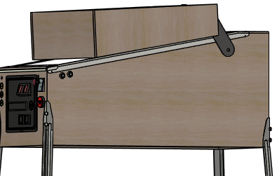
Installing the WPC hinges
One of the advantages of the WPC hinge mechanism is that it's
easy to set up. If you followed the WPC cabinet plans in
Cabinet Body, you've already drilled the mounting holes in
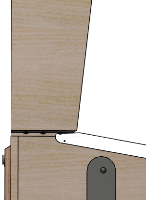
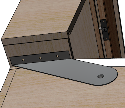
the main cabinet and backbox. To review, the parts get mounted
here:
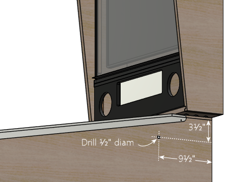
...and here:
See "Backbox floor" in Cabinet Body for
drilling locations, which depend on your cabinet width. If you
haven't already drilled these, an easy way to figure the exact
position is to use the hinge arm itself as a drilling template, after
attaching it to the main cabinet first. We'll point out the right
time to do that in a moment.
You should already have your side rails installed at this point, since
the hinges will get in the way of installing them later.
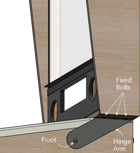
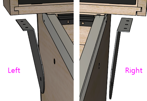
Note that there's a "left" and a "right" hinge arm - they're mirror
images. Be sure to install the correct one on each side. They should
be oriented with the pivot point pointing towards the front of the
cabinet, and the little "wing" that attaches to the backbox pointing
away from the cabinet side:
Start with the hinge pivot joint. This uses the ½" diameter
hole drilled in the side of the main cabinet:
- Fit a ⅜"-16 x ¾" carriage bolt into the squarish opening on the side of the hinge arm. Orient the hinge arm so that it's hanging from the bolt, so that it doesn't swing down into this position on its own and scratch the side of the cab.
- Insert the carriage bolt into the pivot hole in the main cabinet
- From the inside of the cabinet, thread the pivot bushing (Williams part 02-4352) by hand onto the end of the carriage bolt
- Use a ¼" hex wrench to tighten the pivot bushing from the inside of the cab
When tightened, this arrangement should leave a little clearance
(about 1/8") between the hinge arm and the main cabinet, and you
should be able to rotate the hinge arm around the pivot. (It's okay
if it's tight.)
Install both hinge arms (left and right) using the procedure above.
Position the backbox on the shelf at the back of the cabinet, centered
side to side, with its back flush with the back wall of the main
cabinet. (Have an assistant hold the backbox steady while you're
working so that you don't accidentally knock it over.)
Rotate the hinge arm around the pivot until the side with the three
bolt holes meets the bottom side of the backbox. Be careful about
rubbing the sides of the cab so that you don't scratch the artwork.
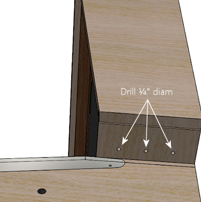
If you haven't already drilled the holes in the backbox floor for
attaching the hinge bracket bolts, this is the time! Make sure the
hinge arm is flat against the bottom of the backbox, and that it's
precisely parallel to the side of the cab. You should be able to see
a little gap between the hinge arm and cab across its whole length.
The hinge shouldn't be pressing against the cab anywhere, since that
could scratch the artwork when you rotate the backbox. Once you have
it aligned to your satisfaction, mark the positions of the three bolt
holes. Repeat on the other side. Remove the backbox and drill
¼" holes at the marked positions.
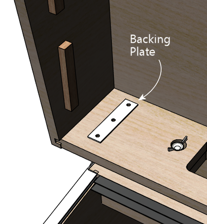
On the inside of the backbox, position the backing plate
(01-9012) over the bolt holes.
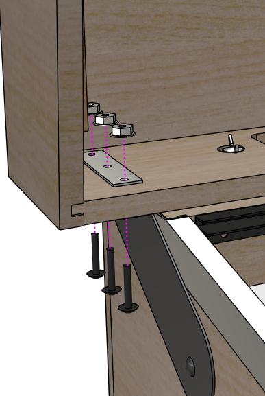
Install three ¼"-20 x 1¼" carriage bolts in each hinge
arm, inserting from the bottom side, and through the mounting plate.
Fasten each with a ¼"-20 whiz flange locknut. Tighten
securely.
The backbox is now attached! You should be able to freely tilt it
forward so that it lies flat against the top of the cab. (It's a good
idea to put down some padding when doing this, so that you don't
scratch up the side rails or the front edges of the backbox.)
If you ever need to remove the backbox, just take out the carriage
bolts attaching the hinge arms to the bottom of the backbox. You can
leave the hinge arms themselves attached permanently.
Alternative hinge mechanisms
Most commercial machines made from the 1990s to present use the WPC
hinge system described above. Most earlier machines that I've
encountered use something more like conventional door hinges, with the
hinges attached at the bottom front of the backbox. The backbox folds
down forwards onto the cabinet, as in the WPC system, but the pivot
point is the door hinge rather than the side bolts. The Williams
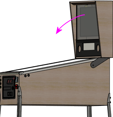
System 11 machines from the 1980s use this approach, as shown below.
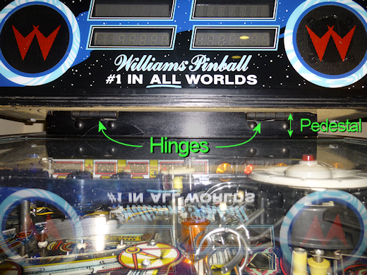
Williams System 11 backbox mounting (Space Station,
1987). This used door hinges at the front of the backbox.
Note how the backbox has to be raised slightly above the
cabinet on a pedestal, to make space when folded down
for the part of the backbox that overhangs the front of the hinge.
I think the WPC system is nicer in a lot of ways, but the door-hinge
system might be a good alternative in cases when the WPC parts won't
fit, such as a mini-cab or an ultra-wide cab. If you use the System
11 machines as your model, pay close attention to the way it requires
a "pedestal" to raise the backbox about an inch above the main
cabinet, to make room for the front overhanging portion of the backbox
when it folds down. The standard WPC plans won't work well with a
hinge like this, because the backbox sits directly on top of the
cabinet in the WPC design. If you want to adapt the WPC plans for
this arrangement, you'll have to add something like the System 11
pedestal.
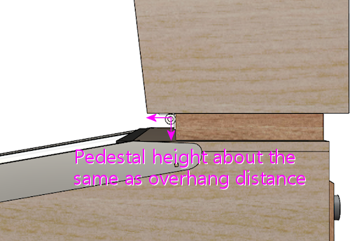
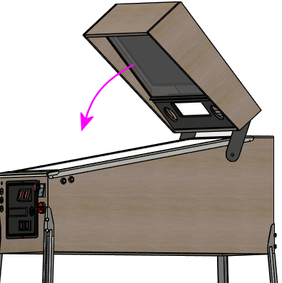
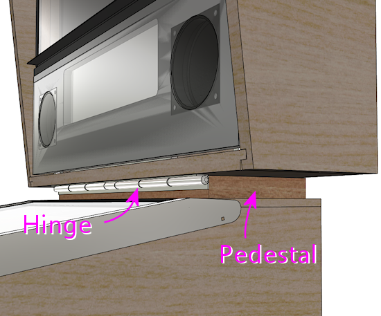
The pedestal has to be at least as high as the distance
the backbox projects out in front of the hinge, to make
room for that part when the backbox is folded down.
Hinge system with backbox folded down.
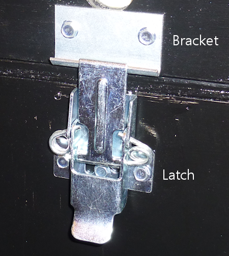
Backbox latch
This is a minor bit of hardware that helps when setting up the
machine, by temporarily securing the backbox in the upright position,
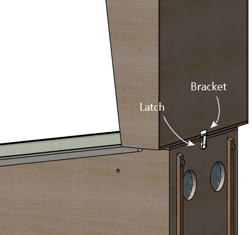
preventing it from falling forward if bumped. The standard part is a
simple toggle latch that attaches to the back of the main cabinet, with
a mating bracket that attaches to the back of the backbox.
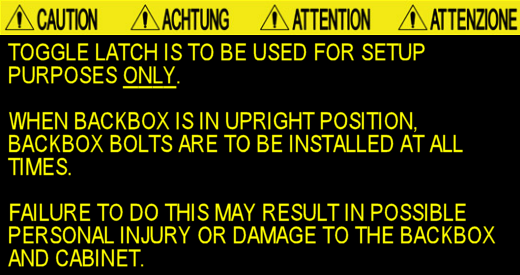
I said "temporarily", because the toggle latch isn't strong
enough to serve as a permanent way of securing the backbox. Let me
show you the warning that they silkscreen on the back of the real
backboxes in big yellow letters:
Their point is that this little toggle latch isn't all that strong; it
could fail if the backbox were bumped too hard. The backbox is quite
heavy and has a lot of leverage, so you need something a lot stronger
to truly secure it. The solution is to install the wing bolts
described below. The toggle latch is just meant to be a temporary
helper while you're getting the wing bolts in place.
Install this after you've set up the backbox hinges, so that you're
working in terms of the actual final alignments.
For fasteners, use any suitable wood screw. On the real machines,
they usually use #6 x ¾" sheet metal screws with hex heads. (I
know, "sheet metal screw" doesn't sound like the right thing for
screwing into wood, but they actually work just fine as self-tapping
screws with plywood.)
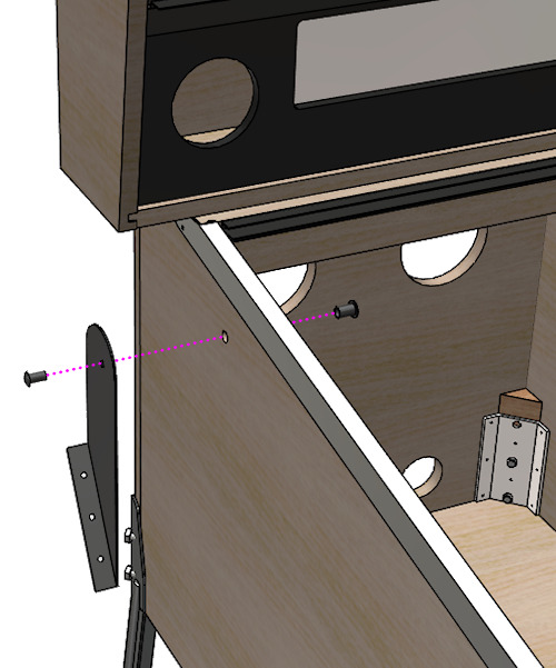
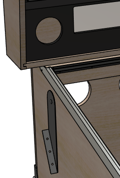
- Set up the machine with the backbox in the upright position. Have an assistant brace the backbox while you're working so that it doesn't fall forward.
- Attach the bracket (the top piece) first. Align it in the center of the backbox side-to-side, with the bottom edge roughly flush with the bottom of the backbox.
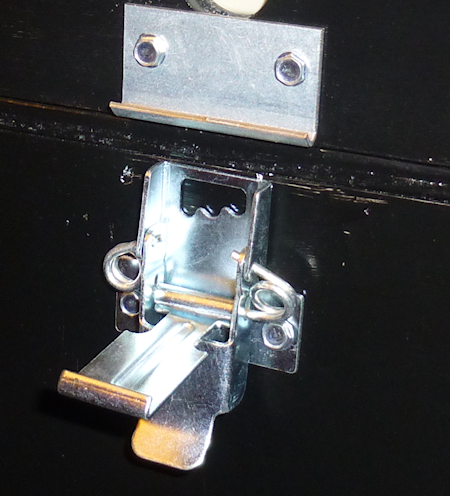
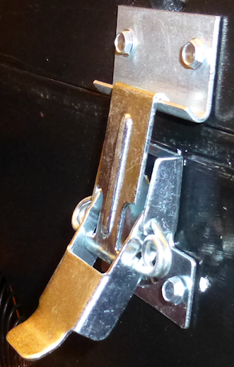
- Figure the position of the latch itself by hanging it from the bracket with the lever pulled partially open, so that there's no tension on the spring, as illustrated below.
- Fasten the bottom bracket at this position. When you close the latch all the way, it should pull the spring tight so that the bracket stays latched.
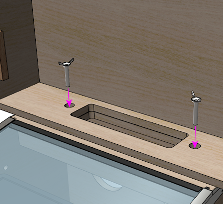
Backbox safety bolts
As the warning placard above points out, the little toggle latch on
the back of the backbox is helpful to keep the backbox from flopping
over while you're setting up the machine, but it's not strong enough
to rely on beyond that. For a deployed machine, you need something
stronger, specifically a couple of big bolts installed in the floor of
the backbox.
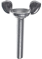
The parts required are a pair of ⅜"-16 x 2" "wing bolts", like
the one pictured below. Wing bolts are basically just regular bolts
with wing nuts in place of the heads. This lets you turn them by
hand, for tool-free installation. (The wing nut at the top isn't a
separate part; it's integral, like the hex head on a regular bolt.)
The wing nut head also serves as a built-in washer.
You can buy wing bolts in the right size from pinball vendors. You
might be able to find them at some hardware stores as well, although
they're too obscure for the big-box stores like Home Depot. In a
pinch, you could substitute ordinary hex-head bolts of the same size,
but note that you'd need to use some kind of giant washers (over 1"
outside diameter) in conjunction, because the hex heads by themselves
will slip right through the 1" top holes (defeating the purpose).
If you've done the necessary prep work as described in the "Rear
shelf" section in Cabinet Body, installing the bolts
is trivial. Just pass them through the holes on either side of the
floor opening and thread them into the pre-installed T-nuts. There's
no need for washers or other parts. Hand-tighten. You don't have to
go beyond hand-tight, since they don't have to hold the backbox up
most of the time; gravity takes care of that for the most part.
The bolts only kick in if the backbox gets bumped or pushed.
What is a translite?
We're all pinball nerds here, so a quick digression on definitions is
in order! There's a bit of a disagreement between virtual
pinball people and real pinball people about what "translite" means.
So to avoid confusion, I want to make sure we're all clear on what
we mean by the word.
Throughout this guide, I use the term "translite" to refer to a
clear plastic or glass sheet that you install in front of the main
backbox TV. There's no artwork printed on it (other than perhaps
some masking around the edges, to hide the TV bezel), since we want to
let the TV handle all of the artwork display. The virtual translite
is thus essentially a bit of trim in a virtual cab to disguise the
TV-ness of our virtual setup and make it look on the outside more like
a real pinball machine.
Okay, so that's how I use the term in this guide. It's also how
the term is commonly understood in the virtual pin cab community, so
that's the way you'll usually see it used on the forums. But
technically speaking, it's wrong! At least, it's not what it means
to (most) pinball people when they're talking about the real machines.
Technically, in a real pinball context:
- A translite is a thin, translucent plastic decal, printed with graphics. There's no glass involved in the translite itself. This plastic decal that they call the translite is then affixed to a clear glass sheet to create a pseudo-backglass. Most modern pinball machines (1990s and later) use this type of assembly in place of a true backglass. It's only a "pseudo" backglass because...
- A backglass is a glass sheet with artwork directly painted or silkscreened on the glass. True backglasses were usually used on machines built before about 1990, when the manufacturers switched to the cheaper translite process.
Those are the technical meanings, but even real pinball people often
use the words translite and backglass loosely and
interchangeably. They'll often call the translite-plus-glass assembly
a translite, or even a backglass. So I think we virtual pinball
people can be forgiven for appropriating translite to mean
kind of the opposite of what it really means, in that we use it to
refer to the plain glass sheet without any artwork.
Creating a translite
The basic material for the translite is a clear sheet of either glass
or acrylic. If you're using glass, it should be tempered glass. I
personally prefer acrylic for the translite because it's so much
lighter than glass.
Dimensions for the standard WPC-style translite:
- Thickness: ⅛"
- Size: 18⅞" high x 27" wide
The size obviously depends on your backbox dimensions.
The size above is for the standard WPC setup, with the backbox built
to the standard dimensions and a standard-sized speaker/DMD panel
installed. If you're not using a speaker panel, you'll probably want
to increase the height to cover the entire backbox area, so you'd make
it about 26½" high if you're using the standard backbox
dimensions.
Where to buy: The clear glass or plastic sheet isn't something you
can find as a standard pinball part from any vendor. Fortunately, it's
easily found as a generic part.
- For glass, you can have a custom glass sheet made by just about any window glass company. Look for local companies that install or repair residential window glass.
- For acrylic, try TAP Plastics or a similar local plastics vendor. You can also buy acrylic in standard sizes at Home Depot and other hardware stores, and cut it to a custom size yourself using a plastic knife. This doesn't tend to make as clean an edge as you'd get from a plastics shop, but that doesn't really matter, since the edges are all covered by trim pieces anyway.
Edge masking
It's nearly impossible to make the backglass TV fill the entire space
that's available for the translite in the standard backbox design.
Part of the reason is that a TV's viewable screen area never
completely spans the full height and breadth of the unit; there's
always at least a thin bezel around the edges. The other factor is
that the backbox space is much squarer than the 16:9 aspect ratio
that's all but universal on current TVs. It's impossible to find a TV
that fills the vertical space fully, given the constraint of also
fitting in the available width. You can get down to a fraction of an
inch of dead space on the sides, but you'll still have more than an
inch at the top and bottom in the best case.
Most cab builders want to cover up all of the dead space around the
edges of the TV, so that only the live display area of the TV is
visible. Understandably, they don't want the insides of the backbox
to be visible.
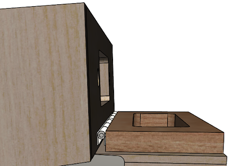
One way that some cab builders deal with this is to create a wood
(or similar) cover with a cutout for the TV area.
I don't personally like this look very much, because to my eye, it
calls attention what it's meant to hide. I mean that it makes it more
even more obvious than it otherwise would be that there's a smaller TV
embedded in a bigger backbox space. I also find that it looks too
different from the real machines, which creates an impression of
home-brew-ness that's at odds with my goal of a realistic appearance.
Given that we're talking about translites, I think you can probably
guess that the approach I prefer is to use a clear glass or plastic
cover for the whole area. That's exactly what the real machines use,
so it looks as close to authentic as you can get, given the inherent
differences in what's behind the glass. But that still leaves the
problem that you can see into the dead space around the TV, since
a clear glass or plastic cover is, after all, clear.
The best solution, in my opinion, is to combine the "cutout" idea from
the wood cover with the clear translite, by masking out the edges of
the translite. There are two ways to do this:
- The easy way is to paint around the perimeter with black spray paint. Paint on the back side of the panel, so that the front has a uniform glossy sheen - that'll largely eliminate the visibility of the "cutout" that I find objectionable in the wood cover approach. Measure the TV display area size, and use masking tape and paper to cover the cutout area. Paint around the edges.
- The other way is to use printed decals to create the mask. You can have custom decals made for this use just like for the cabinet artwork (see Cabinet Art). I used this approach for my own cab, because I figured the real machines have artwork here, so I should too.
I used decals printed in the conventional way, to adhere to the front
side of the translite. It would have been better to print them in a
reverse format, with the adhesive on the graphics side so that they
could have been stuck to the back side of the translite. This would
have created a more uniform finish on the front, just like why you
want to paint on the back if you're using a painted mask.
I really like the way my translite with decals turned out, but for
practical purposes you might be better off with a simple black mask.
The thing that you might not expect about the decals is that you
simply don't see them while playing. The TV display is so much
brighter that it completely overwhelms them to the point of utter
invisibility. Which is exactly what you want, as it turns out: you
want it to look like the backbox of the game you're playing, not like
a TV embedded in a virtual cab. So that works out great, but my point
here is that as far as playing goes, there's no difference between
decals and black paint. And when the cab is powered down, the decals
arguably create the same visual impression that I said I don't
like with the wood cutout approach - the way the visible borders call
attention to what's missing in the middle. But somehow I don't
dislike the look in this flat "2D" version; in person, it actually
looks very much like a real translite, even if it would be a rather
art-impoverished one on a real machine. Even so, a plain black paint
mask would do a better job of hiding the TV cutout when the power's
off; it would just like a solid dark sheet. You could easily
mistake it for a regular translite with really dark graphics that need
some backlighting to come to life.
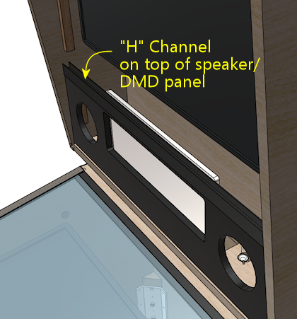
Assembling the trim
The standard WPC translite setup uses four trim pieces around the
edges:
- A "lift channel" at the bottom, part 03-8228-1
- A top trim piece, part 03-8228-2
- Two side trim pieces (one for each side edge), Williams/Bally part 03-8228-2
They're all dead simple to install. Each is a plastic piece with a U-shaped
channel that the glass/plastic sheet fits into. Just align each piece at the
center of its respective edge and press it onto the glass.
Note that the trim pieces don't cover every millimeter of the edges - there's
a little uncovered space at the corners. That's normal.
How to install the translite
If you installed a translite lock, make sure it's unlocked, with the
tab turned "sideways" so that it's not sticking out into the top glass
channel. You'll have to use the key to do this. The whole purpose of
the lock is that the tab blocks the channel so that the glass can't be
removed, but this equally well prevents inserting the glass when the
tab is in the "locked" position.
Holding the translite at an angle, lean the top edge against the
guides at either side of the backbox, and slide it upwards into the
slot at the top.
Lift it high enough into the slot that the bottom edge clears the
bottom trim channel. Holding it by the "lift trim" at the bottom,
move the bottom edge forwards until the translite is flat against
the guides, then lower it into the bottom trim channel until it's
seated.
If you have a translite lock, turn the key to the locked position to
secure the translite. Most pinball owners store the key inside the
coin door, hanging it on a little wire hook that's usually located
alongside one of the coin slots.
How to remove the translite
If you installed a translite lock, insert the key and turn it to the
unlocked position.
Holding the translite by the "lift trim" at the bottom, slide it
upwards until the bottom clears the lip of the bottom trim channel.
That lets you tilt the bottom outwards.
Now just lower the translite out of the top slot. It's now entirely
free of the backbox trim, so you can remove it.
