34. Cabinet Buttons
- Real machines don't all have the same buttons. There are three buttons that are pretty much universal: the two flipper buttons and the Start button. Beyond that, different machines have their own extra buttons, some common and some unique. Some common buttons that appear on many machines are the Magna Save buttons (alongside the flipper buttons), a flipper-like button on top of the lock bar (often labeled "Fire"), an Extra Ball or "Buy In" button on the front of the cabinet, and a Launch Ball button in place of the plunger. If you want to be able to play re-creations of tables with those extra buttons, you'll need some equivalent of the extra buttons on your cab.
- Modern pinball machines have some additional, hidden buttons, inside the coin door, that let the operator access the game's setup menus. It's useful to have these on a virtual cab, too, because you're going to be the operator and will want to be able to access the setup menus.
- Virtual pinball needs some additional controls for the "virtual" aspect, such as inserting virtual coins, navigating the game selection menus, viewing game instruction cards, viewing flyers, exiting an active game and returning to the game selection menu, and controlling the PC audio volume. Many of these functions can be comfortably assigned to the regular pinball buttons (flippers, Start, etc), so you don't actually need a big array of extra controls, but most people find it necessary to have at least one extra button, for the special function unique to virtual pinball of exiting out of the current table.
Minimalist vs. maximalist
Master list of buttons
- Power button: Essential. Pushbutton, bottom of cab, front right side.
On the real machines, the power is controlled with a toggle switch wired to the main power supply line, located in a little recess on the bottom of the cab at the front right corner. In a virtual cab, we usually replace this with a "soft" power button in the same location, wired to the PC motherboard's power control header. See "Floor" in Cabinet Body for details on installing a pushbutton in the proper spot, and Power Switching for more on setting up the PC soft power controls.  Start: Essential. Round pushbutton, front panel, top left.
This is a core button found on every real pinball. Push it to start the game. Most "front ends" (the game menu software that lets you select games to play) also use this as a "select" button when navigating through menus.- Flippers: Essential. Standard flipper buttons, sides of cab.
These are core buttons found on every real pinball.  Exit:
Essential. Round pushbutton, front panel, below Start.
You won't find this button on real pinballs; you "exit" a real pinball game by walking away. But it's a must for a virtual cab. This button exits the current game and returns to the "front end" game selection menu. Front ends typically also use this to navigate within their menu structure (to back out of a menu or acknowledge a pop-up message, for example). Coin In: Essential. No standard location, but commonly either
a round pushbutton on the front panel, or repurposing the Coin Reject buttons on the coin door slots.
This button lets you simulate inserting a coin to add credits to the current game. Even though you'll probably be setting most of your games on Free Play via the operator menus, a Coin button is still needed in some cases, since some older tables simply don't have a Free Play option.
If you have a full coin door with coin slots, you don't absolutely need a separate button for this, since you can use actual coins instead, just like in a real arcade machine. Most coin doors don't come with coin mechs installed, so you'll probably have to separately purchase the mechs (about $10 each for US quarter acceptors) and install them yourself. You'll also have to wire the coin slot microswitches to your key encoder, which is just like wiring a button switch. This is all covered in detail in Coin Door.Even if you do install and wire physical coin acceptors, you might still want to add a separate Coin In button, since a lot of people find it tedious to feed in quarters once the novelty wears off. The most obvious way to add a Coin In function is to simply add one more round pushbutton to the front panel. If you don't like the added visual clutter of another button, though, there's a neat way to hide it in plain sight. Specifically, you can use the "Reject Coin" buttons in your coin slots as your virtual coin buttons. To do that, you have to add microswitches behind the buttons, as explained in Coin Door.
My favorite option is to include both the real coin mechanisms and the Reject button switches. That way you can use real coins when you're in the mood for the full arcade experience, and just push the buttons when you're not.
- Magna Save: Essential-ish. Standard flipper buttons, sides of cab.
This is a second set of buttons on the sides of the cabinet, just behind or below the flipper buttons, using the same button style as the flipper buttons. Everyone calls these "Magna Save" buttons, because a few games in the 1980s famously used such buttons for a magnetic ball-save feature with that trademarked name. Calling them Magna Save buttons is a little misleading, because similar buttons were used on many other pinball machines over the years for all sorts of different special features, but we really don't have a better name, so Magna Save it is.I'm grading these "Essential-ish", because you can get by without them in the majority of games. But if you omit them, you'll give up some important features in a lot of games - many more games than you'd think based on the Magna Save name. Dozens of real tables featured similar buttons. Even if you're a hard-core minimalist about buttons on your cab, there's a case to be made that these buttons appear on enough real pinball machines to be considered part of the basic set of authentic pinball controls. But the real reason to include them is that an even greater number of Visual Pinball tables rely on them for special game-specific features, because these buttons have become the standard fallback for emulating unique controls. You really need these buttons on your cab if you want to enjoy full playability for many Visual Pinball tables. To see what I mean, take a look at the lists in Tables with MagnaSave Buttons.
 Tilt bob: Essential-ish. Inside the cab.
The tilt bob is a little mechanical pendulum that detects excess cabinet motion. This isn't exactly a button, but it acts like one in almost every way - you connect it to the key encoder like a button, and it provides input to the software as though it were a button.Don't confuse the tilt bob with a nudge sensor. The purpose of a tilt bob isn't to simulate nudges in the software, but rather to detect when you're nudging too much. The tilt bob serves exactly the same function in a virtual cab that it serves in a real pinball machine. See Nudge & Tilt for a full discussion of the distinction between "nudging" and "tilting", and the tilt bob's role in this.
Visual Pinball has its own simulated tilt bob, but I strongly recommend installing a physical tilt bob anyway. VP's version just isn't very realistic. The interaction between a real cabinet's motion and the tilt bob's motion is complex; it's one of those compound pendulums that's rather difficult to model, and VP doesn't really try. And I don't see why it should, when we can so easily get exactly the right handling by just hooking up a real tilt bob! That's why I rank this as practically essential. And it doesn't affect aesthetics, since it goes inside the cab.
- Launch Ball: Nice to have if you have a plunger; essential if not.
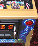 Large round pushbutton, front panel, right.
A fair number of games from the 1990s used a Launch Ball button in place of a regular plunger. This was usually a large round pushbutton, but some games used unique devices instead, such as a gun trigger on Terminator 2: Judgment Day or a gear shift lever on The Getaway: High Speed 2. On the real machines that use such a thing, the button or device is typically positioned exactly where the plunger would normally go, at the top right corner of the front panel.
For a virtual cab, this button is optional if you're going to install a plunger using the Pinscape Controller or the plunger kit from Zeb's Boards. Both of those let you simulate the Launch Ball button using the plunger, so you don't absolutely need the button. Even so, I still recommend including the button in addition to the plunger, since it replicates the original playing experience more faithfully for Launch Ball tables.
Alternatively, you can use a Launch button instead of a regular plunger. All of the PC pinball simulators are designed with desktop use in mind, so they all let you control the on-screen plunger with a key press. You can simply map the Launch Ball button to the software plunger key and dispense with the real plunger. This saves front panel space and the complexity and cost of a real plunger.
In my opinion, the best option is to have both a regular plunger and a Launch Ball button. Controlling the on-screen plunger with a button is possible, but it's a really poor substitute for a genuine plunger. Besides, the plunger is a defining feature of pinball; for me it's simply a must in a virtual cab. If you do choose to include both the plunger and the button, the button can go just above or just below the plunger. I prefer to put the plunger in its standard location on a real pinball, which means the button has to go below it. But some people prefer putting the button above the plunger to make it easier to see and reach, which requires lowering the plunger by a couple of inches from the standard position to make room for the button. I'm not wild about the unusual appearance of the lowered plunger, but some cab builders have to lower the plunger anyway because the normal position is blocked by the playfield TV.
- Audio volume: Recommended. No standard location; preferably hidden.
I find that I adjust the audio volume quite frequently on my cab, so I very much like have a way to do this conveniently. Getting out the keyboard or mouse or opening up the cab don't count as convenient, so some kind of external control for this is recommended.Some people like to use the straightforward approach of adjusting the volume via the amplifier's volume knob, so they locate the amp somewhere easily accessible.
My preference is to control the audio volume via external cabinet buttons for Volume Up and Volume Down. This is possible if you use some software to provide a keyboard interface to the Windows master line-out volume level, such as my PinVol utility.
If your keyboard encoder has the concept of a "Shift" button (Pinscape and the i-Pac encoders do), you don't need separate physical buttons for volume. You can instead double up some of the regular buttons, using them as volume controls in addition to their normal functions. This is the approach I use myself, and I like it because it makes the volume controls easily accessible without requiring any extra physical buttons. I use the right MagnaSave/flipper buttons as Volume Up/Down buttons, in combination with my Extra Ball button as the Shift button. That is, when I press and hold Extra Ball, I can use the right buttons to adjust the volume. Easy, convenient, and requires no extra buttons.
If you prefer separate, physical Volume Up/Down buttons, where do they go? There's no standard location for these, but even the maximalists seem to agree that these particular buttons should be hidden. Some cab builders accomplish this by putting them inside the coin door. That's a little too inconvenient, in my opinion, for something I access so often. A better option is the bottom of the cabinet, near the front edge: that puts them out of sight, but they're easily accessible and you can find them by feel.
Another option that you might prefer is a knob that sends volume up/down keystrokes to the PC. See the vpforums thread Coin Door Volume Control for a way to build such a knob and mount it on the coin door.
- Coin door position switch: Recommended. Inside the
coin door.
The real machines have a switch inside the coin door that senses whether the door is open or closed, like the switch in a refrigerator that turns on the light when you open the door. I'm sure this seems like a ridiculously nitpicky detail, but it's actually important, because a lot of the ROM software on the modern games requires the signal from this switch to access the service menus. (They're so insistent about it because they use it as a safety measure, to cut off the high voltage power supply when the operator is working inside the machine.) Installing the switch to match the software's expectations just makes things easier, and it's not difficult or expensive to install. For full details, see "Coin door position switch" in Coin Door. - Fire!: Nice to have; essential
for Stern fans. Top center of lockdown bar.
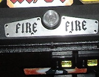 Many newer Stern games (2005 to present) feature this extra button on
top of the lockdown bar, usually centered side to side. (The lockdown
bar is the metal piece at the front edge holding the cover glass
down.) The button itself is usually a clear flipper button and
usually has a lamp inside.
Up until recently, I think many cab builders considered the Fire button to be one of those special, game-specific buttons that isn't widely enough used to justify including it as a physical button. But it's not that game-specific any more, given that nearly every newer Stern title has one. I think it's on its way to becoming a new core button on the strength of Stern's consistent use, and because it's just a good location for an extra button. It's visually appealing even if you're in the minimalist camp, and it's easy to reach during play.
The complication is that you either need a special (more expensive) version of both the lockbar and receiver that are pre-drilled to accept the button, or you need to modify the standard ones. See "Fire button" in Cabinet Hardware Installation for more on finding the required parts.
 Service
buttons: Nice to have. Inside the coin door.
If you're using a real coin door, it will probably come with a little "service button" panel pre-installed on the inside of the door. Modern coin doors for WPC and Stern machines have four buttons here; older 1980s games usually had three buttons. On a real machine, these let the operator access the setup menus for the game, which are used adjust pricing and feature settings and to access self-diagnostics. These menus are where you set up Free Play, for example, or change from 3-ball to 5-ball play. In a virtual cab, you can access the same menus via the authentic buttons if you have them, by connecting the buttons to your key encoder.If you don't have a real coin door, or it doesn't include the service buttons, you can access the service menus via your PC keyboard. This isn't something you have to do very often, so I don't consider these buttons to be essential. But I do consider them to be a big convenience that I wouldn't want to do without on my own machine. Assuming you have a coin door, these buttons don't affect the aesthetics, since they're hidden inside the machine.
- Extra Ball/Buy-In: Nice to have. Round pushbutton, below Start.
 A few games from the 1990s feature an extra front-panel button labeled
"Extra Ball", "Buy-In", or in a few cases something marketing-ese like
"Super Ball". The button on the real machines is either below the
Start button or below the plunger. It lets you
buy an extra ball for a credit after the last ball ends (which can be
a decent deal if you're close to a replay or close to beating the
high score). Realistically, for virtual play, you'll probably never use
it: why bother "buying" an extra ball when every game is free? Even so,
I included one on my machine mostly for completeness, because I like
a lot of games from the era where this button was common. If you
do include it, it also gives you one more option for mapping special
functions in games with unique buttons.
- Night Mode: Nice to have. Hidden; no standard location.
If your cabinet has mechanical feedback devices (contactors, solenoids, replay knocker, etc), you might want to include a button or switch to activate "Night Mode", which turns off the noisy devices for quieter play in the wee hours. The wiring depends on your output device controller; if you're using a Pinscape Controller for feedback devices, you can assign any button input to serve as the Night Mode button. The generic arcade controllers (LedWiz, PacLed) don't have this feature at all, but you can improvise something with a switch that cuts off power to the noisy devices. See Feedback Devices Overview. Like the audio volume controls, this button is an "operator" button that you'll probably want to place somewhere out of view, such as on the bottom of the machine or inside the coin door. With Pinscape, you can assign it as a secondary ("shifted") function of one of your other buttons.  Slam tilt switch:
Neutral. If you have a WPC-style coin door, it will probably have a
slam tilt switch pre-installed. The slam tilt looks like a leaf switch
with a big metal slug attached to the end of the main leaf. It's usually
mounted on the inside of the coin door.
This is related to the tilt bob, but rather than detecting excess motion, it detects excess force. It's triggered by very hard jolts to the front of the cabinet. That big round slug at the end of the main leaf has a lot of inertia, which is what makes the switch work. A hard enough slam will propel the slug by sheer inertia far enough to close the switch and trigger the alarm.
I don't find the slam tilt to be all that necessary on a virtual cab, since its main purpose is to deter the sort of extreme abuse that a coin-op machine in a public place can be subjected to. It's unlikely you'd ever trigger it in regular play, even if you're an aggressive nudger. So I wouldn't go out of my way to add this device if your coin door doesn't already have one. But if it's already there, I'd go ahead and wire it up, since VPinMAME does recognize it as a standard input. The WPC doors usually do come with a slam tilt switch; the Stern and SuzoHapp doors don't.
See Coin Door for more on wiring a pre-installed slam tilt switch and information about how it's treated in the software.
- Virtual service buttons: Kinda nice to have. Inside the coin door.
There are a few miscellaneous "operator" functions specific to virtual pinball that might merit their own buttons inside the coin door, such as engaging night mode, doing a hard reboot of the PC or activating plunger calibration mode. One way to do this is to add your own bank of additional service buttons somewhere inside the coin door. See "Adding an extra service panel" in Coin Door for ideas. - Flyer, Instructions, Info: For the maximalist only.
Below Start.
Some front ends (game selection menu programs) use keys to select selection certain functions within the UI, such as viewing a game's promotional flyer, viewing its instruction card, or displaying other information about the game. Some cab builders include a bunch of cabinet buttons dedicated to these front-end functions. Functionally, you don't really need a bunch of special buttons for the menu program, since the newer front ends let you access everything through the basic keys. You can include them if you like the aesthetics of lots of buttons, though, and they do give you more options for mapping special functions in tables that had unique extra buttons of their own. - Nudge: Not recommended. No standard location. In the early days of virtual cabs, some cab builders added special extra buttons for nudging. This simply transplanted one of the bad features of desktop play (the lack of real physical interaction) into the cabinet, which is the opposite of our ultimate goal of emulating the elements of real pinball play in software. But it was the only option back then, so people did it to have some kind of nudge interaction, even if it wasn't very good. Fortunately, there's a much better way to handle nudging now: use an accelerometer. That lets you virtually nudge the simulated game by actually nudging the physical cabinet. Unlike the bad old days of push-button nudging, where the nudge command was one-size-fits-all, the accelerometer registers the amount and direction of the force you apply, so that the software response can be proportional. It makes the play much more natural and immersive than trying to fumble for buttons at critical moments. See Nudge & Tilt.
Recommendations
- Power button
- Start
- Flippers
- Exit
- Coin In
- Magna Save
- Tilt bob
- Audio volume up/down/mute
- Coin door position switch
- Launch ball (essential if you don't have a plunger)
- Service buttons
- Extra Ball/Buy-In
- Night Mode
- Stern-style lockbar Fire button
- Slam Tilt
- Virtual service buttons
- Flyer
- Instructions
- Info
- Nudge buttons (use an accelerometer instead!)
Illuminated buttons
- there's a switch, which you connect to your keyboard encoder
- and there's a lamp, which you connect to your feedback controller
Incandescent and LED lamps

Common pinball button types
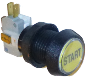
Small round pushbutton
Installation
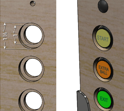
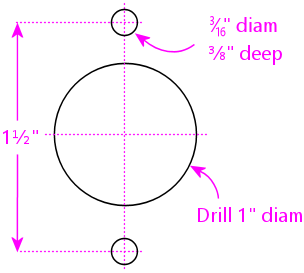
- First, route a 1⅜" diameter inset, ⅜" deep
- Then, drill the rest of the way though with a 1" hole saw bit or Forstner bit (don't use a spade bit - they cause too much chipping with plywood)
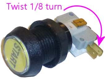
- Gently twist the microswitch base 1/8 turn to release it
- Pull the base out
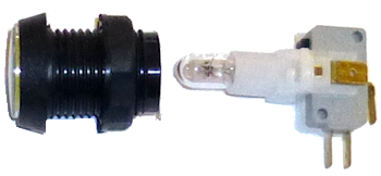
- Remove the nut

- Fit the button into the hole you drilled for it. Insert the button from the outside of the cabinet.
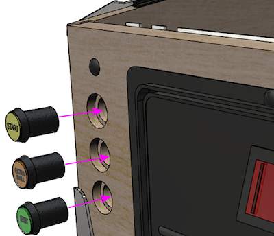
- Fit the nut over the shaft and tighten
- Fit the microswitch base back into the main body; when you find the spot where it fits, press it in slightly and give it a 1/8 turn to lock it back in place.
Wiring
Typical key assignments
- Start = "1" (the digit "1" key)
- Extra Ball = "2" (the digit "2" key)
- Coin In = "3" (the digit "3" key; "5" represents the second or right-hand coin chute in a door with two chutes with different denominations, such as dimes and quarters; "4" represents the middle chute for three-denomination doors, which are rarely seen in the US but are more common abroad; "6" represents a fourth chute, which is typically a dollar bill acceptor in the US)
- Exit = "Esc" (the Escape key)
Custom labels
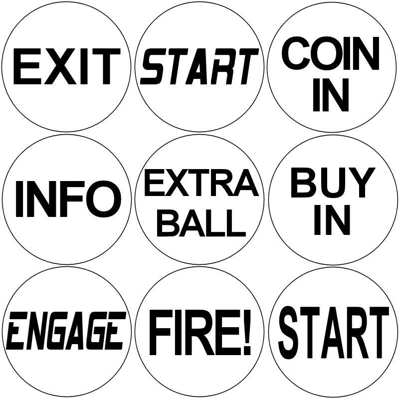
- Use a laser printer only, not an ink-jet printer. Ink-jet inks aren't opaque enough
- Print onto transparency film
- Use film that's specifically designed for laser printers - it has a special coating that makes the laser toner stick properly
- You can use white paper in a pinch, but it's a poor substitute; the paper grain will be visible, and the text won't be opaque enough
- After printing, use an X-Acto knife to cut out the label just inside the circle
- Twist the squarish micro-switch base about 1/8 of a turn to release it, then pull it out of the housing


- On the bottom of the housing, pinch the white prongs together and push them into the housing. This will free the movable part of the pushbutton and let you pull it out the front.
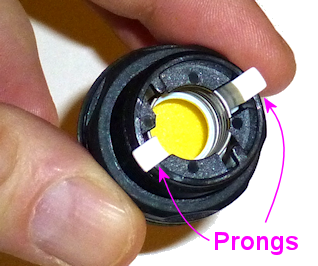
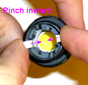
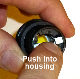
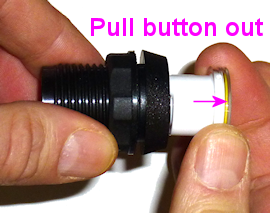
- Now the slightly hard part: pry the lens off the top. This isn't actually that difficult, except that it'll seem at first like it's stuck on there with super-glue and won't come off without shattering. It's actually just snapped on. Use a very small screwdriver, like the type for fixing eyeglasses, and slip it under the lip. Aim for the little notches in the perimeter of the white piece underneath.
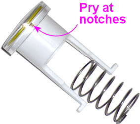
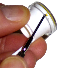
- Pry the lens a little bit at a time at quarter turns until it comes loose; once it's loose, you can just pull it off.
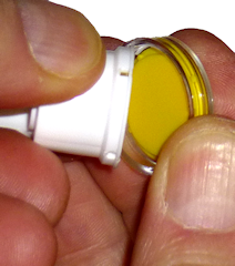
- You'll now have three pieces: the button body, the clear plastic lens, and the colored diffuser.
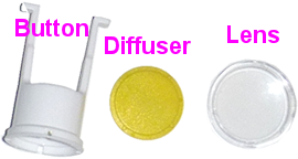
- It's easiest to get the label aligned if you start by fitting into the lens, printing side facing out through the lens.
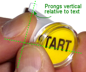
- Fit the diffuser back over the button body, place the lens (with your new custom label) over the diffuser. Note that orientation: the text should be oriented so that the prongs are "vertical" relative to the text.
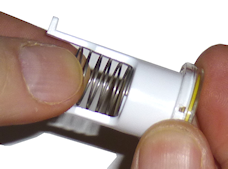
- Fit the spring back into the button body between the prongs
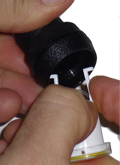
- Compress the spring enough that you can pinch the prongs together and fit them back into the main housing. Push the prongs all the way through the other side.
Launch Ball button
Unique ball launchers
- The gun grip launcher on Terminator 2: Judgment Day (Williams, 1991)
- The phaser pistol launcher on Star Trek: The Next Generation (Williams, 1993) (which was substantially the same equipment as T2's gun launcher)
- The gun launcher on Indiana Jones: The Pinball Adventure (Williams, 1993) (exactly the same idea as the ST:TNG and T2 launchers, but new equipment, styled to look like an antique pistol)
- The fishing reel launcher on Fish Tales (Williams, 1992)
- The gear shifter lever on The Getaway: High Speed II (Williams, 1992) (which, unlike most of the other unique launchers, is more than just a dressed-up button: it has two actions, Shift Up and Shift Down, which are used throughout the game)
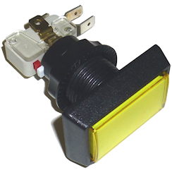
Rectangular pushbuttons
Flipper buttons
- Flipper buttons:
- Standard length (1-1/8"); Williams/Bally part A-16883
- Or: Longer length (1-3/8"); Williams/Bally 3A-7531-5, 3A-7531-9; Stern A-711, 515-7791-00
- Pal nuts (one per button), metal or nylon; Williams/Bally 02-3000
- Leaf switches:
- Flipper leaf switch, single contact, low voltage (gold contact points); Data East/Stern 180-5048-01
- Or: Double-contact leaf switch, low voltage (gold contact points); Williams/Bally SW-1A-192
- Optional: VirtuaPin leaf switch bracket; works with longer (1-3/8") button only
Which color?
Longer or shorter button length?
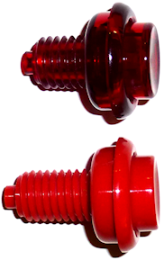
- They work with the VirtuaPin switch brackets
- They're available in more colors
- They're easier to fit into the limited space next to the plunger (especially if you're using a plunger position sensor that needs extra space)
Installing the button
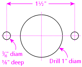
- Using a 1⅛" diameter hole saw, Forstner bit, or straight router bit, drill 5/16" deep from the outside
- Using the same 1⅛" diameter bit, drill 3/16" deep from the inside, on the same center
- Drill the rest of the way through, on the same center, with a ⅝" drill bit
- You're using the VirtuaPin bracket. That bracket provides its own collar on the inside, so you don't need the "neck".
- You're using the LightMite boards to illuminate the button. You don't want the narrowedr neck in this case, because it gets in the way of the LEDs. The wider opening lets you fit the LEDs into the opening alongside the button. And the LightMite board serves as the collar on the inside.
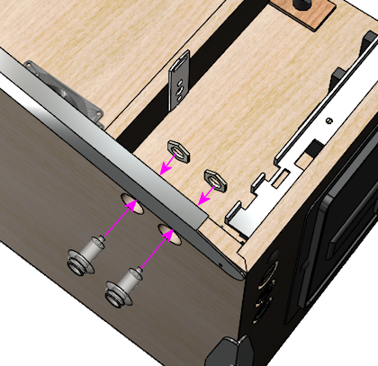
Leaf switch - VirtuaPin holder
- Fit the flipper button into the cabinet hole
- On the inside, fit the switch bracket over the button shaft
- Slip the Pal nut onto the end of the button shaft and tighten
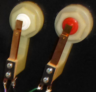
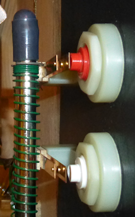
Leaf switch - cabinet wall mount
Switch gap adjustment
Single or double leaf switch?


Flipper feedback effects
Wiring
- Connect the "common" or "ground" key encoder input to the middle blade of the switch
- Connect the regular "Flipper Button" input to the blade closest to the button
- Connect the "Second Flipper Button" input to the blade farthest from the button
Typical key assignments
Left flipper: the left "Shift" key
Right flipper: the right "Shift" key
Left MagnaSave: the left "Control" (Ctrl) key
Right MagnaSave: the right "Control" (Ctrl) key
Second-level contact in a double leaf switch, left side: "L" key
Second-level contact in a double leaf switch, left side: "R" key
Optical interrupter switch
Okay, this is going to seem crazy after all of that lecturing and
haranguing earlier about how you must use leaf switches, but...
The pinball manufacturers stopped using leaf switches in the early
1990s.
That's when they switched to "opto-interrupter" switches. An
opto-interrupter is basically an "electric eye" type of switch, with a
light beam and a receiver that detects if anything is in the way of
the beam. In the case of the new flipper switches, this is all packed
into a compact little unit about a centimeter wide, with a thin gap
between the light source and receiver. There's also a little piece of
plastic that sits in the gap, blocking the light from hitting the
receiver. When you press the flipper button, it moves the little
plastic shield out of the way and lets the light hit the receiver.
That's what activates the switch, taking the place of the direct
electrical contact between the two metal blades in the old leaf
switches.
The first question is, why did they make this change? Reliability,
mostly. The metal contact points on a conventional switch tend to get
dirty over time from dust and grime in the air, plus the metal can
oxidize and abrade. This all makes the contacts become less
conductive as they age, which can weaken the flippers or make them
operate sporadically. The leaf switch blades also tend to lose some
of their elasticity and bend out of alignment from the constant
back-and-forth flexing. Arcade operators always had to spend lots of
time cleaning and re-aligning flipper leaf switches to keep their
machines working properly. The optical switches, in contrast, are
essentially maintenance-free. Arcade operators like that feature
because it keeps their machines working and earning money more of the
time, and reduces their repair budgets. Since arcade operators were
their main customers, the pinball makers often designed around what
the arcade owners wanted, and in this case, opto switches were
desirable because of their improved reliability.
Second question: do the opto switches "feel right"? In other words,
do they have the same force feedback properties and switching action
as traditional leaf switches? In my opinion, yes. Some people
disagree and believe the opto switches have a different and inferior
feel compared with leaf switches, but I can't personally perceive a
difference. I have real machines with both kinds of flipper switches,
and they feel about the same to me. In fact, I owned both kinds of
machines for many years before I even knew about the different switch
types. If you look at the innards of the opto switches, you'll see
that their construction is very much like that of leaf switches,
physically: a flexible plastic blade takes the place of the metal
leaf, and the motion of that blade controls the motion of the light
shield in the optical portion of the switch. The mechanical action is
essentially the same as for a leaf switch. The electronics are
different, obviously, but I don't think that was ever much part of the
feel; the mechanical action is what matters.
Third question: can I use these in my virtual cab? Yes,
with some extra work getting the wiring right.
Fourth question: should I use these in my virtual cab?
Probably not. They're more expensive and more complex to install, and
I don't think there's enough of a benefit for a virtual cab. Remember
that the main benefit of the optos is that they're low maintenance.
That's a big deal for an arcade machine that's getting played all day
every day. It's less of a concern for a home machine, though, since
we don't put nearly as much mileage on it. The electronics in a
virtual cab aren't as hard on the switch, either, since we're using
low voltages. The leaf switches on the old pinball machines directly
switched the 50V coil power, and that high power caused much more
rapid oxidation of the switch contacts than you get with the 3V logic
switching we use. What's more, you can get leaf switches with
gold-plated contact points, and since gold doesn't oxidize, the
contact points won't degrade from age alone.
Fifth question: how can I use these in my virtual cab? If you really
want to use them despite the dubious benefits for home use, it's not
too complicated. The part to buy is the WPC Fliptronic opto board and
switch assembly, Williams/Bally A-17316. (The components are also
available separately.) The opto switches should be compatible with
most keyboard encoder devices; wire them as normal, connecting the
Ground (GND) pins on the opto board to the Ground or Common terminal
of the encoder, and connecting the SW1 (switch 1) and SW2 (switch 2)
pins of the opto board to the flipper button inputs on the encoder.
These boards have two optos to provide the same effect as a
double-contact leaf switch; if you only want a single-contact switch,
connect SW1 and leave SW2 unconnnected. You also have to supply the
board with a +12V power supply connection to the labeled pin; this
powers the light source for the optical switch.
Tilt bob
The easiest option is to buy a complete tilt bob assembly; look for part
A-15361 at the pinball vendors. You can also buy the parts separately:
- Mounting plate A-15360
- Upper bracket 01-3444
- Lower bracket 01-3445
- Pendulum 03-8668
- Plumb bob wire 535-5319-02
- Plumb bob 535-5029-00
You'll also need two #6-32 x 3/8" machine screws to assemble the pieces to the
mounting plate, and two #6 x 1" wood screws to mount it to the cab wall.
You can skip the mounting plate if desired and simply screw the two brackets
directly into the cab wall. The mounting plate just makes it easier to get
everything aligned properly.
In the real machines, the tilt bob is usually installed on the left
side wall near the front of the cab.
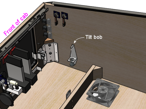 When installing, you should have the machine set up with its legs
attached and leveled, so that the machine is sitting at the same angle
that it'll have in regular use. Angle the tilt bob so that the
pendulum is centered in the ring when at rest.
Adjust the sensitivity of the tilt by moving the plumb bob up or down
on the hanger wire. (Loosen the thumb screws to free the plumb bob to
move up and down; tighten them again when the plumb bob is at the
desired position.) A tilt is signaled when the plumb bob comes into
contact with the surrounding ring, so it increases the tilt
sensitivity when you move the bob upwards on the wire (reducing the
margin between the bob and the ring). You can always come back and
adjust the sensitivity after play-testing if it's too sensitive or too
permissive.
To wire the tilt bob, connect one wire from the keyboard encoder to
the terminal on the upper bracket, and connect the other wire to the
terminal on the ring bracket.
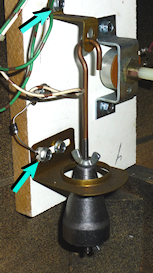 The standard keyboard assignment for the tilt bob in Visual Pinball is
the letter "T" key. But some extra configuration is required! See
"How to configure VP for a tilt bob" in Nudge & Tilt.
Slam tilt
A slam tilt switch is a leaf switch with a big weight slug attached to
the main leaf. This detects excessive jolts to the cabinet via the
mechanical inertia of the slug.
WPC coin doors normally have a slam tilt switch pre-installed, so all you
have to do is connect its wires to your keyboard controller.
See Coin Door for details on how to access the pre-installed
wiring in the WPC door.
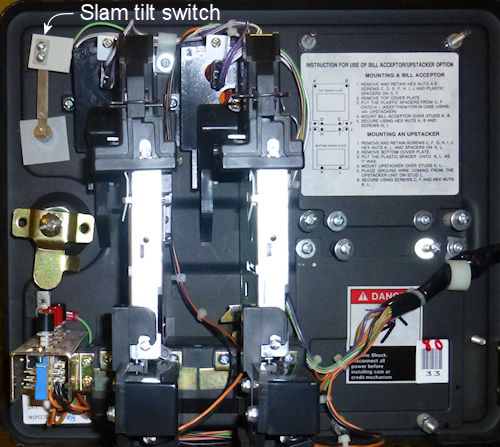 Slam tilt switch in a WPC coin door (interior side of coin door shown).
The WPC doors typically have the switch pre-installed.
If your coin door doesn't already have a built-in slam tilt switch,
and you want to install one separately, look for these parts at the
pinball vendors:
- Weighted leaf switches: B-8372, 27-1066, 502-5032-00
- Mounting bracket (should be usable with any of the above): 01-1168
- Weighted switch with mounting bracket (pre-assembled): B-9141
- Planetary Pinball Supply weighted switch with mounting bracket: A-17195
 Slam tilt switch with bracket, mounted to cabinet floor.
It'll also work mounted to the front or side walls. Install
near the front of the cab.
Mount the switch to any convenient spot on the cab floor, front wall,
or one of the side walls, close to the front end. It should be within
a foot or so of the front so that it'll be triggered if the front is
lifted and dropped.
To wire, simply connect the wires from your keyboard encoder to the
two leaf switch terminals.
The standard keyboard assignment for a slam tilt in VPinMAME is the
"Home" key (the cursor navigation key).
Service buttons
If you have a WPC coin door with built-in service buttons, the buttons
can be connected through the coin door's wiring harness.
See "Wiring to the key encoder" in Coin Door
for details.
The Stern/SuzoHapp coin doors don't typically come with service
buttons installed. You can separately buy a Stern 4-button service
assembly (Stern part number 515-1963-00) that fits these doors. These
come with four pushbuttons that you have to wire yourself. Connect a
wire from the Common/Ground of your keyboard encoder to one terminal
of each button (you can daisy-chain this connection across the buttons
- there's no need to run a separate wire for each button back to the
encoder). Connect the other terminal of each button to a unique
key input on the encoder.
The standard key assignments for these buttons are:
- Green button = Cancel = "7" (the "7" keyboard key)
- Left red button = -/Down = "8" (the "8" keyboard key)
- Right red button = +/Up = "9" (the "9" keyboard key)
- Black button = Enter = "0" (the "0" keyboard key)
If you're not using a standard coin door, but you want a service
button panel somewhere, you might be able to adapt the Stern 4-button
panel above to another mounting location. Or you could just get some
small pushbuttons and attach them somewhere convenient with an
improvised mounting. Wire them and assign keys the same way
described above.
Coin door position switch
This is covered in detail under "Coin door position switch" in
Coin Door.


