98. Connecting the Expansion Boards
Before connecting of disconnecting any of the expansion board cabling,
you should have the power off to the PC and all of the power supplies.
The same applies for seating and removing the KL25Z in the main board
sockets.
Attach the KL25Z
The KL25Z simply fits into the sockets on the main board. It only
fits in one way, since the sockets are asymmetrical.
In addition, connect the "KL25Z port" to the PC via a USB cable.
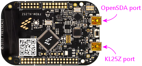
The "KL25Z port" is the one that Pinscape uses for all of its joystick
emulation, keyboard emulation, and output controller features. The
"OpenSDA port" is only needed when downloading new firmware onto the
KL25Z, so you don't have to leave it plugged in all the time. But
it's fine to do so - it doesn't interfere in any way with normal
controller operations. I leave it plugged in on my cab so that I
don't have to mess around with connecting cables when I want to update
the firmware; it's always plugged in and ready to go with updates.
Connect power cables
All of the expansion boards have two power input: one labeled
PC PSU and one labeled 2ND PSU. Both of these inputs
must be connected to power in order for the boards to operate.
The connectors on the boards use special cables that you can
build yourself. See Expansion Board Power Cables for full instructions.
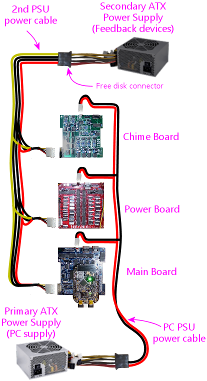
The PC PSU connector is meant to connect to the ATX power
supply that's powering your PC motherboard. You should connect
the cable for this connector to a free disk power plug on your
PC's power supply.
The 2ND PSU connector is meant to connect to a separate,
"secondary" ATX power supply that's dedicated to powering your 5V and
12V feedback devices, such as flasher LEDs, light strips, motors,
fans, beacons, and possibly solenoids.
Do I really need two power supplies?
Not absolutely, but it's better to use two.
If you have some serious constraint that prevents using two supplies,
you can get away with sharing a single ATX power supply for
both the PC power and the feedback devices. The reason we recommend
against this is that it places a lot of load on the one PSU. Some of
the feedback devices draw enough power that they can momentarily
overwhelm the PSU's voltage regulator, especially when switching on
and off, which can make the PSU's output voltage levels fluctuate.
Exposing a PC motherboard to that kind of fluctuation can cause
glitches, such as USB disconnects or random Windows crashes. Using a
separate power supply unit avoids placing that kind of load on the
PC's supply.
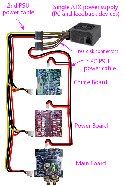
If you do decide to run everything on a single power supply, the
expansion boards still need both connectors to be plugged in.
In this case, you simply plug both connectors into the main PC power
supply, rather than plugging them into separate supplies.
Connect the first power board to the main board
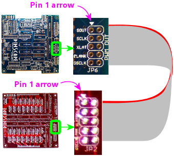
Connect the power board to the main board via a 10-pin ribbon cable.
See Ribbon Cables if you haven't built this cable yet.
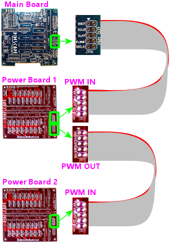
This cable connects between JP6 (PWM OUT) on the main board
and JP2 (PWM IN) on the power board.
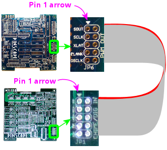
Be sure to align pin 1 on both ends of the cable. I recommend
marking a red stripe along one edge down the whole length of the
cable, and calling that the Pin 1 side. That makes it easier to
get the orientation right at both ends, since all you have to do
is align the red stripe with the "Pin 1 arrow" marked on the board
at each end.
Connect additional power boards
If you're using two or more power boards, connect their data cables
in a daisy chain, from the PWM OUT port of one board to the PWM IN
port of the next board:
- The second board's PWM IN port connects to the first board's PWM OUT port
- The third board's PWM IN port connects to the second board's PWM OUT port
- And so on
Connect the first chime board to the main board
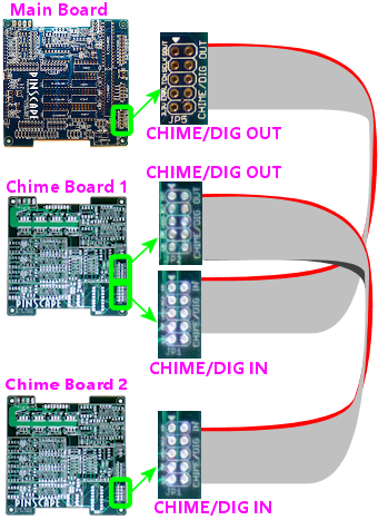
Connect the ribbon cable between the main board's CHIME/DIG OUT port
(JP5) and the chime's board's CHIME/DIG IN port (JP1). As with the
power board ribbon cable, make sure that the cable is aligned so that
Pin 1 on the main board header connects to Pin 1 on the chime board
header. I recommend marking a red stripe on one edge for the whole
length of the ribbon cable to mark the Pin 1 side, to make it easier
to get the orientation right when plugging it in.
Connect additional chime boards
The chime boards connect in a daisy chain, like the power boards.
In this case, you connect the CHIME/DIG OUT port of one boards to the
CHIME/DIG IN port of the next board.
Connect the plunger sensor
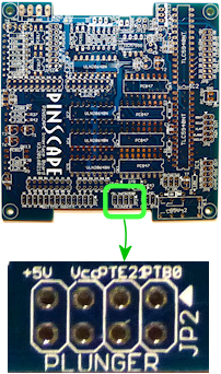
The plunger sensor connects to the main board pin header marked
PLUNGER (JP2).
 The easiest and best way to connect to this header is using a ribbon
cable. There's a separate chapter for each type of plunger sensor,
and each contains instructions for building the ribbon cable connector
for that sensor. Also see Ribbon Cables for general
instructions on building ribbon cables.
When connecting the plunger sensor connector, take care to line up the
Pin 1 connection on the plunger sensor with the Pin 1 arrow
marked on the main board.
Connect button inputs
The buttons all connect to the header on the main board marked
BUTTON INPUT (JP1).
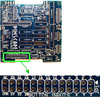 The numbered pins on this connector correspond to individual button
inputs. The pin marked CMN is the "Common" pin.
Physically, pin cab buttons are typically either microswitches (such
as the SuzoHapp pushbuttons most people use for the front panel
buttons, such as Start and Exit) or leaf switches (usually used for
flipper buttons). In either case, the part you wire to the expansion
board is a "Normally Open" switch - a switch with two terminals that
come into contact when you push the button. To wire a button to the
expansion board, then, you connect one terminal of the switch to one
of the numbered button input pins, and you connect the other terminal
to the CMN (Common) pin. All of the buttons connect to the Common pin
(thus the name!), but each button gets its own individual numbered
input pin.
Full instructions for connecting the buttons can be found in
Pinscape Button Inputs, and much more information about buttons in
general (a list of all of the common pin cab buttons, what to buy,
how to install buttons in the cabinet) is in Cabinet Buttons.
The pin header is designed to mate with a 26-pin crimp housing
(listed in the parts list). For help assembling crimp pin
housings, see Crimp Pins.
Some advice on assembling the crimp pin housing for this connector:
I'd start with an empty housing (without any wires installed yet), and
gradually install the wires as you install the buttons themselves.
One nice thing about these crimp pin housings is that you can insert
pins one at a time, so there's no need to install all of the pins at
once. Each time you install a button, run the wiring from the button
back to the expansion board, crimp a pin on the end of the wire, and
insert the pin into the housing.
The one pin you probably will want to install up front is the Common
wire, since all of the buttons will need to connect to that. You
might want to connect that to a terminal block or something similar,
so that you can easily add more wires that connect to this same
common point as you add more buttons.
TV ON connections
See TV ON Switch for details on connecting the TV ON switch.
IR remote control connections
See IR Remote Control for how to connect the IR remote control emitter.
Feedback device connections
See Pinscape Outputs Setup (Expansion Boards) for how to connect feedback devices
to the expansion boards.


