112. IR Remote Control
The Pinscape software is equipped to send and receive IR remote
control codes. This is primarily for the sake of the
TV ON feature, which can power up your TV(s) at
system startup by sending them the necessary IR codes. But you can
also use it to transmit any remote control codes you wish at any time,
and to translate received IR codes into Windows key presses, allowing
a remote control to effectively serve as extra "buttons" on your
cabinet.
There are two completely separate hardware projects here: an IR
transmitter, which sends out the codes to your TV, and an IR receiver,
which can receive codes from your remote control in order to learn the
codes specific to your TV or to accomplish those button-press
capabilities we mentioned.
The expansion boards include both the IR transmitter and receiver as
standard features. You can also build them as add-ons for a
standalone KL25Z with a small amount of external circuitry.
Wiring the transmitter and receiver
An IR transmitter isn't anything too exotic. It's really just an LED
that emits infrared light. Consumer electronics use a pretty standard
range of IR wavelengths, so all we have to do is select an IR LED that
emits light of the right "color".
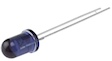
Physically, an IR LED looks like other small LEDs. The only obvious
difference is that the case is often opaque or dark plastic rather
than the clear plastic you'd find in an optical-wavelength LED.
The Pinscape software controls an IR LED through a GPIO port on the
KL25Z. The software rapidly turns the LED on and off to form a
pattern of flashes that your TV interprets as a remote control
command.
An IR receiver is a more specialized device, purpose-built to read and
demodulate signals from an IR remote transmitter. But fortunately
they're quite cheap and easy to connect. They're actually easier to
connect electrically than an IR LED is, because they don't need much
in the way of additional parts.
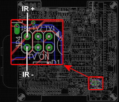
Connecting an IR emitter to the expansion boards
The IR transmitter LED connects to the "TV ON" pin header on the main
expansion board, also labeled JP4. This header has six pins; the
IR LED connects to the two pins in the column labeled IR+.
You don't have to connect anything else to these pins besides the IR
LED. Just connect the LED so that its long leg connects to
the IR+ pin, and the short leg connects to the IR-
pin.
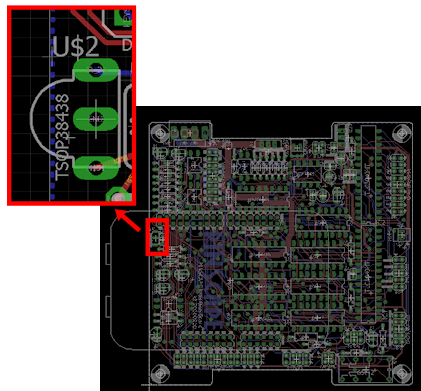
Connecting an IR receiver to the expansion boards
Simply install the IR receiver chip directly in its spot in the
expansion boards. You'll need to bend the legs at a 90° angle
to that it doesn't stick out too far, as it nestles in under the
KL25Z.
No expansion boards: using a pre-built kit
If you're not using the expansion boards, and you'd rather not build
any external circuits by hand, there are some ready-made kits
available. The ones I've seen are designed for Arduinos, which is
another microcontroller (similar to the KL25Z, but different hardware)
that's popular with robotics hobbyists. I haven't
tested any kits myself, but I've heard from a couple of people who
have successfully used this kit:
If that product link isn't working, you might try searching for similar
products on Amazon or at hobby robotics vendors like Pololu
or Adafruit.
The transmitters and receivers for IR remotes are fairly standardized,
so there's a fairly good chance that similar kits will be compatible
with the KL25Z electronics and the Pinscape software.
Wiring the receiver:
- Connect VCC on the receiver board to one of the 3.3V pins on the KL25Z (pins 4 or 8 on J9)
- Connect GND on the receiver board to one of the GND pins on the KL25Z (pins 12 or 14 on J9)
- Connect DATA on the receiver board to the GPIO pin you've selected for input. Any interrupt-capable GPIO pin can be used, which means that you can use any PTAxx or PTDxx port. Configure the port you select as the IR receiver pin in the Pinscape Config Tool settings. See Selecting GPIO pins below.
See KL25Z Pin Out for the KL25Z pin wiring diagram.
Wiring the transmitter:
- Connect VCC on the transmitter board to one of the 3.3V pins on the KL25Z (pins 4 or 8 on J9)
- Connect GND on the transmitter board to one of the GND pins on the KL25Z (pins 12 or 14 on J9)
- Connect DATA on the receiver board to the GPIO pin you've selected for the transmitter output. A PWM-capable port must be used. Configure the port you select as the IR transmitter pin in the Pinscape Config Tool settings. See Selecting GPIO pins below.
See KL25Z Pin Out for the KL25Z pin wiring diagram.
No expansion boards: Build your own IR transmitter
The recommended IR LED (TSAL6400) is relatively powerful as LEDs
go, so the KL25Z can't drive it directly from a GPIO port. A small power
booster circuit is needed. All you need is a simple
transistor amplifier. Here's the schematic:
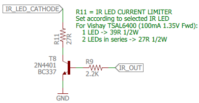
This is the same circuit used on the expansion boards (the
diagram above is actually taken from the expansion board
schematics).
- Connect the short leg of the LED to the wire labeled IR_LED_CATHODE. The convention for all LEDs is that the long leg is (+) and the short leg is (-).
- Connect the long leg of the LED directly to the +5V power supply.
- Connect the wire labeled IR_OUT to the GPIO port on the KL25Z that you're using for the IR output. See Selecting GPIO pins below.
- Connect GND to one of the ground pins on the KL25Z. See KL25Z Pin Out.
Selecting resistor R11
Choose the resistance value
for R11 according to whether you're using one LED or two:
- For one LED, use a 39Ω, ½ Watt resistor
- For two LEDs, use a 27Ω, ½ Watt resistor
No expansion boards: Build your own IR receiver
The recommended IR receiver device, TSOP38238, contains
both the optical sensor and the demodulation circuitry.
You just need two additional parts (a resistor and a
capacitor) to connect it to the KL25Z. Here's the
connection diagram:
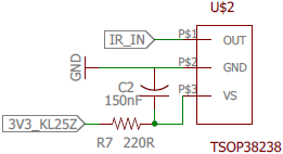
- Connect IR_IN to a GPIO port on the KL25Z that you're using for the IR input. See Selecting GPIO pins below.
- Connect 3V3_KL25Z to one of the 3.3V pins on the KL25Z. See KL25Z Pin Out.
- Connect GND to one of the ground pins on the KL25Z. See KL25Z Pin Out.
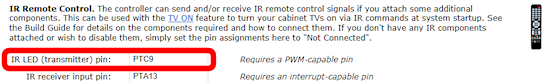
Selecting GPIO pins for the power sensing circuit
The IR transmitter can use any PWM-capable GPIO pin on the KL25Z.
The default for the expansion boards is PTC9, but you can use any
pin with PWM capability.
For a list of PWM pins, see KL25Z Pin Out. The Config Tool
will also show you the available pins if you go to the IR section
on the Settings page and click on the "IR LED (transmitter) pin"
box:
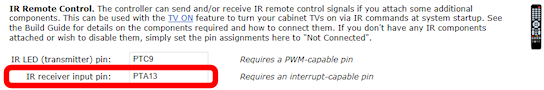
The IR receiver can use any interrupt-capable GPIO pin. The
default for the expansion boards is PTA13, but you can use any
pin in the "PTAxx" or "PTDxx" groups. See KL25Z Pin Out
for all interrupt-capable pins, or click on the "IR receiver
input pin" box in the IR section on the Settings page in the
Config tool:
Positioning the IR transmitter LED
Assuming you're using the IR transmitter to control a TV, it's best to
place the LED as close as possible to the IR receiver window on the
TV. You can run as much wire as necessary between the LED and the
expansion board port (or your own circuit) to position the LED
properly.
Using two IR transmitter LEDs
You can connect two IR LEDs instead
of just one. This can be useful if you need to control two
TVs, since it lets you position a separate transmitter near
each TV's IR receiver. To connect two LEDs, connect them in
series:
- Connect the +5V supply to the first LED's long (+) leg.
- Connect the first LED's short (-) leg to the second LED's (+) leg. You can run as much wire between the two as needed to position the two LEDs properly.
- Connect the second LED's short (-) leg to the IR_LED connection in the schematic.
Learning IR commands from your remotes
Once you have the hardware installed, you can use the Pinscape Config
Tool to learn IR command codes from your remotes. Once Pinscape
learns a command code, you can use it for various functions:
- Transmit it at system startup to power up your TV
- Transmit it when you press a button
- Send a key press when the IR receiver receives the code
To learn IR codes:
- Launch the Pinscape Config Tool
- Go to the Settings page
- Scroll down to the IR Remote Control section
- Under that, you'll find the IR Command List
section:
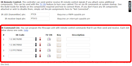
- The IR Command List shows a list of the commands that Pinscape has learned. Initially, this will be empty, so it will just show one empty row.
- To learn the first code, click the "learn" icon (
 )
in the empty first row.
This will bring up another window that will lead you through the programming
process.
)
in the empty first row.
This will bring up another window that will lead you through the programming
process.
- Get your IR ready, pointing at the Pinscape IR receiver
- Click the Learn button in the dialog
- Press and hold the button on the remote that you want to learn
- The "learn" window will show a graphical representation of the learned code, showing the series of on/off light pulses used for the raw bits of the code. If it captures a code successfully, click Save to store the code.
- After you've entered a code into the first blank row, a new blank
row will appear. You can continue adding more codes the same
way. The "learn" button ()
programs the code for the row that you click on, so you can go
back and replace any row's code with a new code later if you want.
- You can enter a description for each code (such as the name of the remote control button it's associated with) in the Description field. This is just to help you keep track of which buttons you've programmed, so you can enter anything there that will help you identify the button in the future.
- Remember to click "Program KL25Z" at the bottom of the Settings page when you're done, to save the settings in the device.
Using a code to power on a TV
The IR remote feature was primarily designed to be used with the
TV ON feature that powers up your TVs at system
startup, so the remote control code list has a special provision
to use a code with the TV ON system.
After you've programmed a code, you'll notice that there's a little
TV ON icon ( )
in the row next to the code. Just click this icon to activate
the TV ON feature for the code. When this icon is activated,
Pinscape will automatically send the code at system startup,
after a delay that you can program in the TV ON section in the
Settings page.
)
in the row next to the code. Just click this icon to activate
the TV ON feature for the code. When this icon is activated,
Pinscape will automatically send the code at system startup,
after a delay that you can program in the TV ON section in the
Settings page.
How to transmit an IR code via a Windows command
In your Pinscape Config Tool install folder, you should find another
utility program called PinscapeCmd.exe. You can use this
program to make Pinscape transmit any of the IR command codes it
knows at any time via the Windows command line.
- Open a CMD prompt
- Go to the Pinscape Config Tool folder: CD /D C:\PINSCAPE (or wherever it's installed)
- Type PinscapeCmd SendIR=1
The SendIR command transmits the learned command code in the given
slot. If you go back to your IR command list, the number corresponds
to the row number in that list.
You can put that command in a .BAT script as well, so you can send IR
commands from any programs that can launch .BAT scripts, such as
PinballX or PinballY, or automation programs like AutoHotKeys.
How to transmit an IR code when you press a button
You can program Pinscape to send an IR code when you press a cabinet
button. This might be useful if you want to set up a hidden button
that turns your TV on or off, for example.
- Open the Config Tool
- Go to the Settings page
- Scroll down to the Button Inputs section
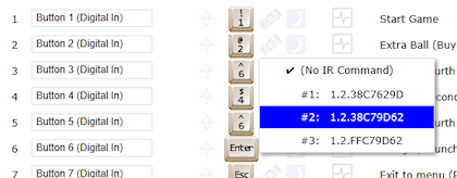
- Click the Remote Control icon in the row for the button you want to assign
to an IR command
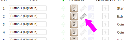
- Select the learned IR command code to send from the list
- Click Program KL25Z to save settings
- Now whenever you press that button, the associated IR code will be transmitted
How to send a Windows keyboard key press when an IR code is received
You can also program Pinscape to send a key press to Windows when the
IR receiver sees a given IR code. This lets you turn a remote control
into a set of additional "buttons" that you can use to access Windows
functions, without festooning your cabinet with even more physical
buttons.
To make this work, you'd have to situate your IR receiver where it can
"see" IR codes from your remote. The expansion boards don't really
make a provision for this, since they situate the receiver right on
the main board, where it'll probably be hidden away inside the
cabinet. I guess you could open the coin door and point the remote
inside. If you really want to use this feature regularly, though,
you'd have to come up with a fancier setup where you move the IR
receiver somewhere more accessible, like behind an opening in the
front of your cabinet.
Aside from those complications with physically getting the IR signal
to the receiver, it's easy to set up the IR-to-key-press feature:
- Open the Config Tool
- Go to the Settings page
- Scroll down to the IR Remove Control section
- Click on the key-cap icon for the command you want to associate with a key press
- That will show the same key/joystick selection popup that's used to map buttons to key presses, so just select a keyboard key or joystick button in the usual fashion
- Click Program KL25Z to save settings
- Now whenever the IR receiver receives that code, Pinscape will send the associated key press to Windows
