52. LED Resistors
LEDs always require something to limit the amount of current
(amperage) going through them. Without some kind of current limiter,
an LED acts like a short circuit, which will make it overload itself
or its power supply. So it's always necessary to put something in the
circuit that sets a safe limit on the LED's power consumption. The
simplest and most common way to do this is by placing a resistor in
series with the LED.
Which LEDs need resistors?
All LEDs require something to limit current, but some LEDs
come with suitable resistors already built in. You don't
need to add anything external for devices with their
own built-in resistors.
How can you tell if resistors are built-in?
A rule of thumb is that any LED that you buy as a bare component
requires an external resistor, whereas finished products that
happen to contain LEDs usually have any necessary resistors built in.
Here's a handy guide to which is which, for the parts commonly
used in pin cabs:

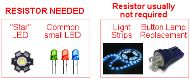
- "Star" LED: external resistor required
- Common small LED: external resistor required
- Light strips, standard type: resistors are built in
- Light strips, addressable type: resistors are built in
- LED #555 replacement bulbs: resistor is built in
- LED #161 replacement bulbs: resistor is built in
Special exception: You don't need a resistor with any type of
LED when using it with a "Small LED" output port on the Pinscape main
expansion board. The Small LED outputs are special in that they have
their own built-in current limitation, which makes an external
resistor unnecessary. This exception doesn't apply to the Pinscape
flasher output ports or any other output ports; it only applies to
the "Small LED" ports.
How to wire the resistor
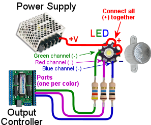
Here's the basic wiring plan for connecting a
current-limiting resistor to any LED feedback device:

As you can see, this doesn't change the basic wiring plan for an
output device, it just adds to it, by inserting the resistor into
the wiring between the LED and the output controller.
Note that it's equivalent to insert the resistor into the
positive voltage wire (the one that connects the LED to the power
supply) instead of the negative wire (to the output controller port).
You can do that if you prefer it for some reason. But it's almost
always more convenient to put it on the negative side, as shown,
because it's usually easier to daisy-chain all of the positive voltage
connections together. In fact, for some RGB LEDs, the negative side
is the only option because the positive connections for the three
color channels are sometimes wired together inside the LED.
I'd recommend keeping things simple by adopting a uniform rule that
the resistor always goes on the negative side.
For an RGB LED, each color channel needs it own resistor. In
fact, the resistor values for the three channels might even be
different. When you're calculating the resistor values (which we'll
come to in a moment), you should do a whole separate calculation for
each channel. Even though an RGB LED looks like one LED, it actually
has three physically separate LEDs inside, each with its own current
and voltage specs.

Basic resistor wiring plan for an RGB LED.
This type of LED has separate connections for the three color
channels. Each color channel must be wired to its own resistor.
Note: the order of the pads shown here won't necessarily
match your LEDs.
Choosing a power supply
In most cases, you can use a 5V supply for LEDs.
LEDs should always list a "forward voltage" value, sometimes written
VF. This is usually somewhere between about 2V and 4V.
Red LEDs tend to be at the lower end of that range, and blue and green
are at the higher end. A common point of confusion for new cab
builders is what this voltage means for the power supply. The forward
voltage isn't the same as the supply voltage: you don't have to
use a power supply that exactly matches the LED's forward voltage.
Rather, the forward voltage tells you the minimum required
supply voltage.
The basic rule is that the supply voltage has to be higher than the
forward voltage. Ideally, it shouldn't be too much higher, because
the higher it is, the more power will get wasted as excess heat burned
up by the resistor.
5V is usually the ideal choice, because it's the lowest common
supply voltage that's high enough to work with most LEDs.
Choosing the resistor
The exact resistor you need depends on the LED. To figure the right
resistance value, you need to know two electrical specs for the LED
and one for your power supply:
- The LED's Forward Voltage, sometimes written as VF
- The LED's Forward Current, or IF
- Your power supply voltage, which we'll write as Vsupply
You should be able to find the LED figures on the LED's packaging,
the manufacturer's data sheet, or the eBay seller's page where you
bought it. If you buy from eBay, be sure to write down those figures
when you place your order, since eBay pages don't always stay
around indefinitely.
The power supply voltage is simply the voltage of the power supply
you're using to power the LED. It's best to use the lowest power
supply you have that's above the VF voltage. For
example, if VF is 3.2V, any power supply higher than
3.2V will work, so you should use your 5V supply.
For an RGB LED, you'll need three resistors - one per color
channel. What's more, you might need different resistors for each
color. In the specs for the resistor, you should find separate
VF and IF values for the Red, Green, and Blue
components. Calculate each resistor value separately, as though
it were for a separate LED (which it really is).
Once you have those three figures, plug them
into this interactive calculator to figure the required resistor
type:
Important: Pay attention to the reported wattage value!
Choose a resistor with the specified wattage or higher.
If you use a resistor that has too low a wattage rating, it could overheat.
Please pay close attention to the "ohms" units reported by the calculator.
If the calculator says 5.6Ω, it truly means 5.6 Ohms, not
KΩ. If the calculator comes up with a value in in KΩ, it will
say so. This might seem too obvious to belabor, but this is a
frequently asked question! If you've done some electronics work, you
can get so accustomed to only seeing resistors in the 100s or 1000s of
ohms that something like "five Ohms" looks like a typo. But it's not -
there really is such a thing as a 5.6Ω resistor, without the "K".
And that's about the size you usually need for the high-power
"Star" RGB LEDs. So if the calculator comes up with 4.7Ω or 5.6Ω
or something else in the single digits, don't assume there's an implied
"K" that was accidentally omitted. 5.6Ω really means 5.6Ω.
The calculator rounds the resistance value up to the nearest
standard resistor value that's commercially available, to make it easier
to find a matching part to buy. It also builds in a safety factor for the
wattage by assuming that you don't want to go above 60% of the rated wattage for
the resistor. The "raw results" are the exact mathematical results
of the calculation before those adjustments, but those exact sizes
usually aren't available for purchase anywhere, thus the adjustments.
In case you're interested in the details, the calculator
figures the resistance value based on this formula:
Once you have those three figures, you can simply plug them into
this formula to calculate the resistance required:
R = (Vsupply − VF) / IF
By the way, if you bring up the on-line version of this chapter
in your Web browser, you'll find a handy interactive calculator
that does this calculation for you, and automatically applies
the adjustments described below to round to a standard size. It
also calculates the required wattage.
Note that formula takes the Forward Current (IF)
value in Amperes, not milliamps. The LED will probably specify
IF in milliamps. To convert from mA to Amps, simply divide
by 1000. For example, if IF is quoted as 20mA, use 0.02
Amps in the formula; if IF is 350mA, use 0.350 Amps.
The result R is in Ohms (Ω). It's not in KΩ
or any other multiplied value - it's in plain old Ohms.
For a high-power "Star" RGB LED, you might be surprised to get a
value in the single-digit Ohms range, like 5.2Ω. That's
perfectly normal, so don't second-guess the formula and think the
result needs to be in a different unit. As long as you entered
the inputs correctly in Volts and Amps (not milliamps),
the result is always in Ohms.
The mathematical result of the formula tells you the exact resistance
you'd need in theory to get the desired current. But you can't buy
resistors in just any size; they only make them in certain standard
sizes. The standard resistor sizes are 1Ω, 1.2Ω, 1.5Ω,
1.8Ω, 2.2Ω, 2.7Ω, 3.3Ω, 3.9Ω, 4.7Ω, 5.6Ω,
6.8Ω, and 8.2Ω, plus each of these values multiplied by 10,
100, 1000, 10,000, 100,000, and 1,000,000.
So after you figure the theoretical R value with the formula, round
up to the nearest standard size. For example, if the formula
says you need a 4.9Ω resistor, round up to the next standard
size of 5.6Ω.
We're going to call this rounded-up value the adjusted
resistance. (Sorry if this is starting to feel like filling out
a tax form!)
After you figure the resistance value and round up to a standard
size, the next step is to calculate the required wattage for the
resistor. This is important because resistors generate heat, so
you need to buy a resistor that's capable of handling the amount
of heat it's going to generate.
To calculate the wattage, plug the adjusted R value (the
value rounded up to a standard size) into this formula:
Iactual = (VS - VF) / Radjusted
That will tell you the actual current you're going to get with
the adjusted resistance value. Now plug the result of that
formula into this formula:
W = (VS - VF) * Iactual / 0.6
That yields the amount of power the resistor uses in Watts, and adds a
safety margin so that we never operate above 60% (that's the 0.6) of
the maximum rating for the resistor. That's just to make sure we're
not pushing our luck, and accounts for any manufacturing variations in
the LED or resistor that make them a little outside of their rated
specs.
As with the Ohms value, they only make resistors with certain wattage
ratings, so you'll have to choose the next available larger wattage.
Common wattage values for resistors are ⅛W, ¼W, ½W,
1W, 2W, 5W, and 10W.
Now you're set to go out and buy resistors! Go to an electronics
vendor like Mouser and enter the Ohms and Watts values you just
calculated. You should be able to find matching parts. If you have
any trouble finding something with the required Watts value, it's
always safe to use a larger rated wattage. For example, if the
formula says you need 5.6Ω at 1W, it's fine to use a 2W resistor
instead. Larger wattage resistors are physically larger as well, so
it'll take up more space if you have to use a much higher wattage than
the formula gives you, but it will be perfectly functional and safe.