Appendix 13. Lock Miter II: The Special Router Bit Way
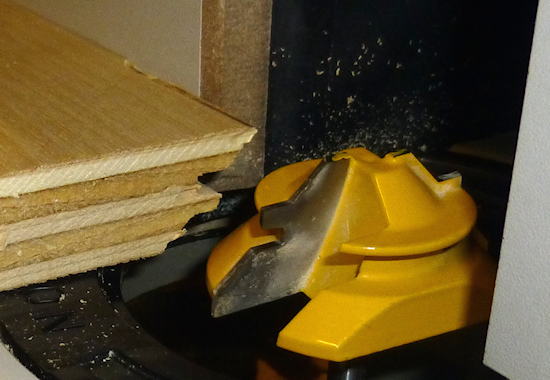
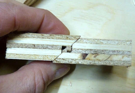
A lock miter bit set up in a router table, and a sample piece
of 3/4" plywood showing the pattern that the bit cuts in the
edge of the wood.
This section covers making a lock miter corner join using
a special router bit purpose-built for this join. For an
introduction to lock miter joins in general, see the previous
section, Lock Miter I: The Plywood-Friendly Way, which also describes a
different way of making this type of join using just a
straight router bit and a table saw.
I get the impression that practically everyone implementing lock
miters these days uses the special bits, rather than the more manual
approach of the previous section. It's easy to see why. The router bits only require one pass
over each edge, compared with about six separate cuts per corner for
the manual method. There's less risk of screwing up one of
the steps, or cutting one of them slightly out of alignment, if you only have to make one cut in the first place.
But there's a catch - actually, a few catches. One is
that the bits are expensive (ranging from about $25 for one that's
cheap and priced accordingly, to over $100 for a really nice one).
Another catch is that they're notoriously difficult to set up
properly. The reputation isn't undeserved; when you read through the setup
procedure below, you might start to think that six cutting steps
doesn't sound like so much trouble after all. Yet another issue is
that lock miter bits don't always perform well with plywood (some
people would rephrase that to "they always don't perform well with plywood").
The bits are really designed more for solid wood. They do work with plywood to
some extent, but the small tongue-and-groove features don't always hold up well, and the veneer
can get chipped up if you don't take some extra precautions (which
we'll outline below).
You might wonder what's so different about the manual approach that
makes it work so much better with plywood. The difference is the size
of the tongue-and-groove features. The features are about twice as
large when you use the manual approach. The smaller features in the
router bit approach are just too delicate for most plywood. Follow-up
question: why can't they make the router bit's features as big as
the manual method's features? That's because the router bit has
to cut a mirror-image pattern. That's only way that you can use
the same router bit to cut both sides of each corner - one side has
to be the mirror image of the other for the pieces to fit together.
The mirror image means that every feature has to be there twice.
And this all has to fit into the thickness of the board. That's
why the features are half-sized compared to the manual method,
where the cuts are complementary instead of mirrored.
I really like the idea of the lock miter bit, but I've found to my
surprise that the "plywood-friendly" approach isn't any harder, and
might even be a little bit easier. It's still a bit of work, but when
you take into account the lengthy setup procedure for the lock miter
bit, plus all of the extra precautions you have to take during the
routing process, it might actually be more work overall with the
special bit. Another practical drawback of the router bit method is
that the bits are rather frighteningly large and probably more
dangerous than typical router bits. Despite the disadvantages,
though, the lock miter bit has the appeal that it should produce
predictable and repeatable results after you get it calibrated
properly. The plywood-friendly procedure involves more cuts, which I
think is inherently scarier to a newbie woodworker like me, since
there are more chances for something to go wrong.
If you do decide to try the lock miter bit approach, I'm hoping that
the information in this section makes it at least a little easier for
you to carry it out. Below you'll find a step-by-step recipe that I
think is fairly complete and should produce good results if you follow
it carefully. You can also find lots of Youtube videos about how to
use lock miter bits, which I recommend seeking out - it's always good
to see a new technique in action before trying it yourself, plus
you'll get other perspectives on the right techniques. My procedure
is almost the same as what everyone else recommends, but I think I've
boiled it down to a more precise recipe than I've seen elsewhere.
I've also made a couple of improvements to the usual setup advice that
I think will help you get better accuracy with less work, and I've
added tips about a couple of issues peculiar to pin cab construction.
How lock miter bits work
Lock miter bits achieve one-pass operation by
using a symmetrical (mirror-image) pattern for the adjoining edges
at each corner. You route one edge with the face horizontally
on the router table, and you route the other edge with the face
held vertically against the fence. The symmetry allows
the two sides to mesh when joined at 90°.
The trick to making the corners align is to get the midpoint of the
mirror-image pattern exactly at the center of each board. That's
where all of the notorious setup difficulty comes from - you have to
hit that center point almost perfectly for the corners to align.
And you have to do it in two dimensions simultaneously - bit height
and fence depth.
The setup procedure is complex, but there's a pretty reliable recipe
for it, and it doesn't require superhuman woodworking skills or feats
of measurement. It's all based on iterative testing and adjusting,
using a methodical approach that should (if all goes well) quickly converge on the right
setup. Once you've dialed in the alignment, you just lock it down and
route all of your boards with that same fixed setup. You don't have
to make any further adjustments after the initial alignment - in fact,
it's critical that you don't make any changes, since you want
all of the cuts to be identical.
Does a lock miter bit even work with plywood?
A lot of woodworkers say no. In fact, the owner of VirtuaPin has
mentioned that he doesn't use lock miters for the cabinets he sells
because lock miters don't work well enough with the plywood stock he uses.
He's undoubtedly talking about the lock miter bit rather than the
plywood-friendly method, since that actually does work well with most
good-quality plywood.
You might say, "Well, Williams used it, so it must work." It's true
that Williams used a lock miter join on their 1990s cabinets, but they
didn't do it with the mirror-image bits. If you look closely at their
cabinets, you can see that they used the technique described in
Lock Miter I: The Plywood-Friendly Way instead.
My own experiences with the lock miter bit have been mostly successful.
I've used it with mid-grade plywood from Home Depot for a few
projects, and it works, with some reservations. To
illustrate the kind of results I've seen, here are some photos from
my "vertical sled" build (which has its own section later in this
chapter).
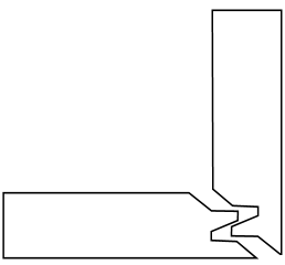
Sample of lock miter results, using 3/4" birch plywood from
Home Depot. This is an ordinary mid-grade plywood,
suitable for a paint-grade project like a pin cab. The
lock miter routing is very clean on the horizontal side,
which is cut parallel to the grain. The vertical side is
cut across the grain, which is harder on the veneer, but
still comes out pretty clean, especially if we pre-score
the veneer. I left a section at the top un-scored to
show the difference that pre-scoring can make. This
one actually isn't bad even in the un-scored section -
I've seen much worse chipping in other projects.
It probably helped that I routed this one in two passes.
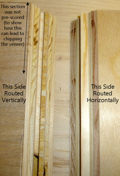
Another view. There's a little blow-out (chipped veneer)
at the end on the horizontally routed side - this is the
trailing end where the router bit came out. I'll just sand
it, but you could probably prevent it entirely by pressing a
sacrificial board up against this end as you run the board
through the router. On the vertical side, you can see that
the lock tongue didn't survive the routing fully intact. It
should be a perfect mirror image of the horizontally routed
side, but it's quite stunted compared to the
other side. And what's left is so delicate that it will
easily flake off if you're not really gentle with it.
The reason this comes out so poorly is that we're trying to make a very
thin strip out of the layered plies, and that just doesn't
work. The horizontal side works better because it leaves
basically one whole ply intact for the tongue. (And it's
unavoidable that we have to route the vertical side into
the plies like this - it's inherent in how these bits work.)
There's enough structure remaining
that the join will still work, and it'll still self-align
like it should, but we do lose some strength from
the missing material.
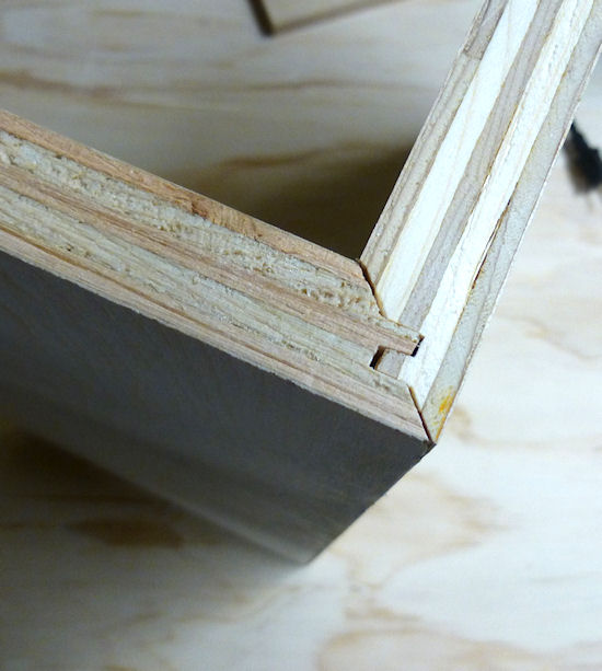
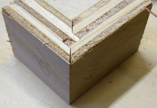
Dry fit of the two pieces above. The lock miter is tight enough
to hold the corner together with friction for a test fit, which
makes it really easy to do the final assembly.
After pointing out all those flaws, I should clarify that the end
result still usually looks nice once the corner is assembled.
The flaws are mostly on the inside, where the glue goes, and where you
can't see them in a finished cab. Most of my attempts have yielded
nice sharp corners and unblemished outer veneer.
Will you get decent results with the plywood you're using?
I can't say for sure, given the mixed experiences I've seen on the Web.
The lock miter clearly works with some plywood, but maybe not all
plywood. It's probably a function of the particular material
and/or the particular router bit. I think the only way to find
out if it'll work for your batch of plywood is to test it. One nice
thing about the elaborate setup process is that it can also serve as
a fitness test for the plywood stock, since you have a to make a bunch of test cuts and construct
at least one test corner. You should be able to tell from the test cuts whether
or not you'll get a clean enough result. If you're not happy with
the way things look during setup, you can always fall back on the
plywood-friendly technique instead.
Equipment
Lock miter router bit: These are available from several
manufacturers. They all use the same basic idea of the
mirror-image shape and the horizontal/vertical routing process.
I use an inexpensive no-brand bit I found on Amazon, and it
does an acceptable job.
Note that there are also two-piece lock miter bit sets that use
complementary bits for each side of the corner rather than a
mirror-image pattern. Those require a different setup not covered in
this section.
Setup jig: Optional, and in my opinion, not all that
helpful. If your bit comes with one, go ahead and use it,
but I wouldn't go out of my way to buy one separately from the bit.
It's too hard to make sure that the jig exactly matches the bit if you
have to buy them separately, since different bits have subtly different
shapes.
The point of the setup jig is to help set the initial height of the
bit without having to check it against the board you're cutting. The
thing that makes this of dubious utility is that you still
have to go through the test-and-adjust procedure described later
in this section, since it's so important to calibrate the bit height
to the actual plywood you're using. A setup jig helps with the initial
height estimate, but that's not the time-consuming part, so it
doesn't really save you that much.
Router and router table: If you already have a hand router, you
can buy a bench-top router table and use it with your hand router.
Most of the the bench-top tables are compatible with many routers from
many brands, so you can generally mix and match brands. I use a
relatively inexpensive table from Skil, which works pretty well. It's
not a high-end piece of precision equipment, but it's been good enough
for the pin cab joinery I've attempted, including lock mitering.
I'm afraid I don't know of any way to use lock miter bits with a
hand router alone - I think you really need a table for this job.
Router table fence micro-adjuster: Optional but really helpful.
Provides a way to adjust the fence position in tiny fractions of an
inch, to help get the alignment perfect. This is something you can
make yourself as a simple DIY project, as described in
Lock Miter I: The Plywood-Friendly Way.
Vertical sled: Optional but really helpful, especially when
lock-mitering for a project that involves large pieces (such as a pin
cab). This is another DIY project discussed below.
Router bit setup procedure
Important: don't set up your lock miter bit until you're ready to
route all of the pieces that you want to route with it. The setup
is the hard part, so you want to be able to set it up once and do all
of your routing in one go.
The lock miter bit has to be set up so that the height and depth of
the cut are exactly matched to your plywood stock. The only way I've
found to do this is to do a series of test cuts, and make small
adjustments based on how well the test pieces fit together.
The bit height and fence depth settings are independent, so you can
get one dialed in first, then do the other one. The procedure that
seems to work best is to get the height adjusted perfectly first, then
set the depth.
The setup all hinges on the symmetry of the cutting pattern. The goal
is to get the pattern perfectly centered on each board. When the
centers are aligned, the corners are aligned. Remember that each
corner will consist of one piece that runs through the router
horizontally, and one piece that runs through vertically. The router
bit has to be set so that its height above the table centers the bit
relative to the horizontal cut, and the fence has to be set so that
the bit is centered for the vertical cut.
For safety, always unplug your router before making adjustments
to the bit height or fence position.
Step 1: Cut a piece of plywood to use for setup and testing, using the
same stock you're using for the lock miter corners. The exact size
isn't too important, but something like 5" x 18" should work.
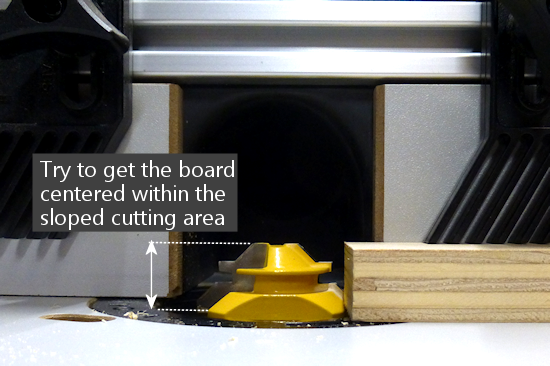
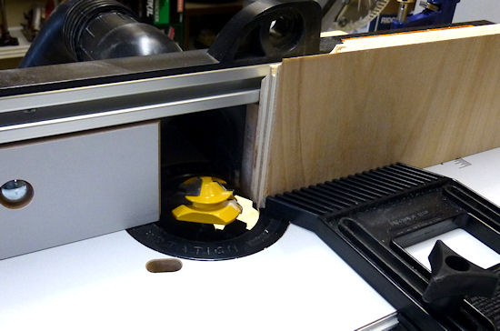
Step 2: Put the test piece on the router table next to the bit. By
eye, adjust the bit height so that the board is centered within the
bit's slanted cutting area.
Most of the Youtube videos on the lock miter want you mark a
center-line on the board, and align that with the center of the bit.
If you like that idea, go with it. I find it easier to judge by the
overall height, especially with 3/4" plywood and a 3/4" bit, since the
cutting area of the bit is just a hair taller than the board. It's
mostly just a matter of getting the bit lined up so that the board
is completely within the cutting area. If you're using a larger bit or a
thinner board, it might be easier to work with center marks, but even
then I'm not sure. At any rate, it doesn't have to be perfect at this
point, since we'll micro-align it based on a test cut shortly.
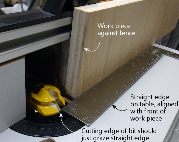
Step 3: Set the initial fence position. As with the initial bit
height, this is only an approximate starting point, so you don't have
to spend a ton of time here. Rotate the bit so that the cutting edge
is pointing straight out at you (make sure it's unplugged first!).
Put a metal straight-edge on top of the board and against the fence,
and slide it across until it crosses in front of the bit. The goal is
to align the fence so that the ruler just barely touches the cutting
edge.
Note that most of the Youtube tutorials use this method to set the
final fence position, but I've never been able to get it accurate
enough this way. We'll fine-tune the fence later using a more
precise method.
Step 4: Place the test board flat on the router table, against the
fence. Turn on the router and feed the board in for just a short
distance - about 2". Take it out, flip it over, and feed it in
again from the other side, again for just 2" or so.
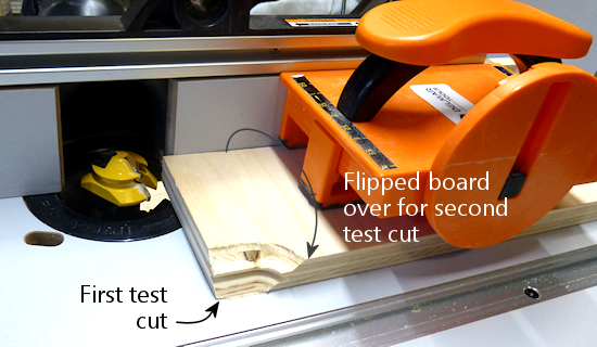
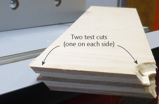
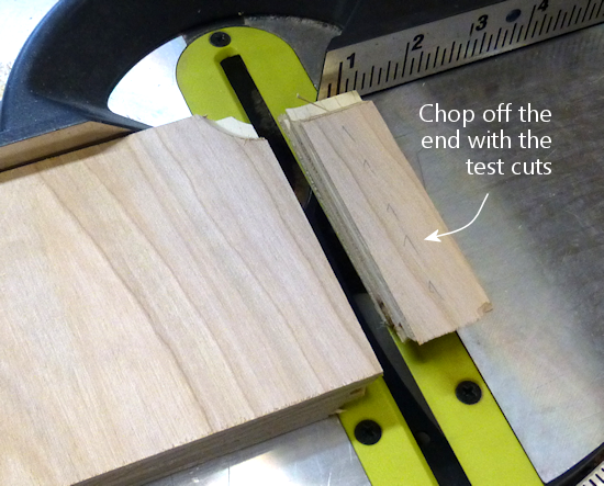
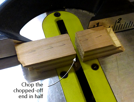
Step 5: Cut the short section you just routed off the end of the board,
then cut that strip in half. Flip one half over and fit the routed
sections together to test the fit.
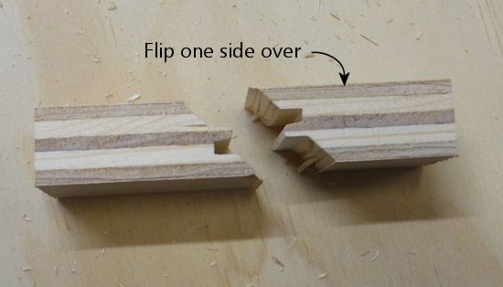
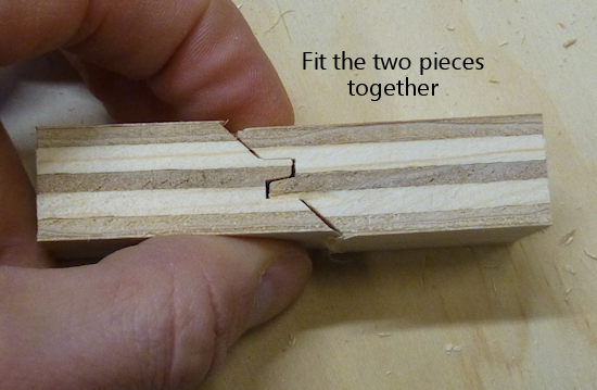
Step 6: The goal is for the two pieces to be aligned perfectly. The
top and bottom surfaces of both halves should line up exactly, so that
you practically can't even feel the seam when you run your finger over
it. If by some miracle they're exactly aligned after that first test
cut, you're already done setting the bit height! But they'll probably
be a little off at this point, as in the test fit photo above.
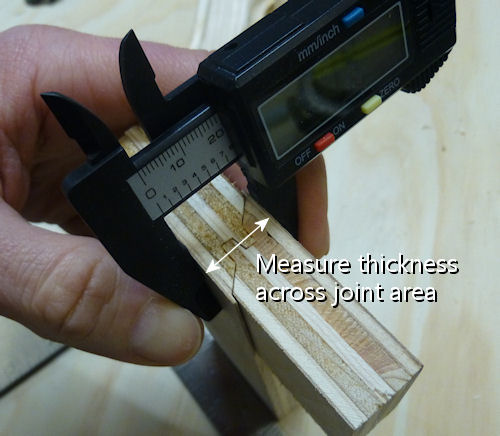
To correct for the offset, you have to move the router bit up or down
by half of the offset distance. So ideally, you need to know the
exact numerical size of the offset. If you have digital calipers,
measure the thickness across the joint section, then subtract the
thickness of the board itself (as measured with the calipers) to get
the offset distance.
If you don't have calipers, you can try using a ruler, or you can just
make an estimate by eye. You'll converge on the magic spot more
quickly if you can get a more precise reading, though. I can usually
get it just about exact on the second try when I use calipers.
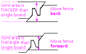
Step 7: Move the router bit up or down by half of the offset
distance, according to the direction of the offset:
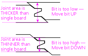
Which way to adjust the router bit, based on the
direction of the offset. The easiest way to tell
is by looking at whether the joint
section is thicker or thinner than the
individual boards.
Most routers have a micro-adjustment dial for the depth that lets you
change the depth in tiny fractions of an inch; for example, my
router's dial has ticks at 1/128". Refer to your router manual if
you're not sure how to use that. It helps a lot in this step to be
able to control exactly how much you're changing the depth on each
iteration.
Step 8: Repeat the whole test, and check the new vertical offset. If
it's still off, measure it again and adjust the bit height by half of
the offset distance, using the same up-or-down rule as before.
Keep repeating until the two test pieces align exactly.
Try to get the alignment practically perfect before declaring victory
and moving on to the next step. Any error at this step will manifest
as double the error in the cabinet width and/or length, which could
affect the fit of your lockbar, TV, or other parts.
Step 9: Once the height is perfect, we need to adjust the fence
position to get the depth perfect. The procedure is the same, but
this time you do vertical cuts instead of horizontal cuts.
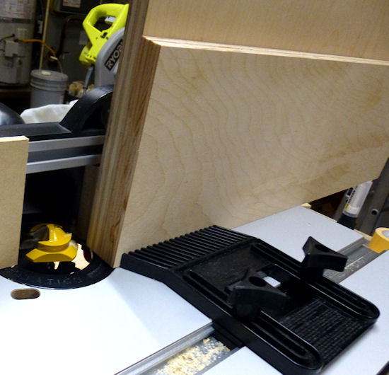
Preparing to make the vertical test cut. Hold the test board
vertically against the the fence while running it through the
bit. It's helpful to use a featherboard to keep it pressed
against the bit without placing your hands close to the
bit (a push block would also work).
As with the horizontal test cuts, make two short (2" or so) cuts,
cut off the ends with the routing, flip one piece over, and
fit them together. The goal is to have the top and bottom
surfaces perfectly aligned. If they're not aligned, we need
to adjust the fence to make the cutting depth deeper or
shallower.
In this case, if the joint section is too thick, move the fence
back, away from the front of the table. As before, we move the
fence by half of the offset distance.
As in the previous step, repeat the test-and-adjust process
until the two pieces are exactly aligned.
This is the step where the value of the fence micro-adjuster
mentioned earlier becomes obvious. Before I built the micro-adjuster,
this step could be incredibly frustrating as I kept overshooting
the magic center spot in one direction and then the other, trying
to estimate tiny fractions of an inch by eye.
The screw adjuster makes it a lot more controllable.
Step 10: The height and depth should now be dialed in. I'd do one
final test run at this point, but this time, make an actual corner
join: using two scrap pieces, run one piece through horizontally, and
run the other piece through vertically. Fit them together to make a
corner. The result should have the seam exactly at the corner.
Remember that any deviation from the seam being exactly at the corner
will throw off the assembled width and/or length of your cabinet by
twice that amount, so don't settle for close-enough. Even if you can
tolerate a little cosmetic imperfection in the corner placement, the
size deviation after assembly could turn out to be a practical
problem. It's worth trying to get it perfect at this stage.
If it looks good, you're ready to route your actual work pieces.
Don't touch the router setup again until you're done routing all
of the corners - you want to make sure the perfect alignment
remains locked in until you're done.
How to route the corners
Before you start doing the routing, I have a couple of other pieces of
advice to help improve your results, so you might want to read through
the sections below before proceeding.
When you're ready to perform the routing, start by going around the
corners and designating the horizontal and vertical routing sides.
You need one horizontal side and one vertical side at every corner.
It's up to you which is which, but you have to be sure that every
corner uses complementary orientations for its two adjoining faces.
My scheme is:
- Front face is routed horizontally on both sides
- Back face is routed horizontally on both sides
- Left side is routed vertically on both ends
- Right side is routed vertically on both ends
I do it that way because I find it easier to handle the long side
pieces in a vertical orientation by using a "sled" (see below).
To make sure that I don't get anything confused, I always take a
pencil and mark each of the edges I'm going to route - "Lock Miter
Here Horizontally This Face Down", "Lock Miter Here Vertically This
Face To Fence". All of the routing must be done on the inside
faces, so I mark the inside faces only. I like to include "Face Down"
or "Face To Fence" so that I'm more likely to catch myself if I'm
about to feed a board in the wrong way, since I'll be looking
at a face-up marking telling me it needs to be face-down.
Once you have everything marked, checked, and double-checked, it's just a
matter of running the edges through the router as marked. Again,
always be sure to route with the inside face down (for horizontal
cuts) or towards the fence (for vertical pieces).
After all the routing is done, assembling is just a matter of fitting
the pieces together. Lock-mitered corners tend to hold together
pretty well just by friction, which makes it easy to do a dry fit
to test that everything aligns properly.
Use a second layer to reduce chipping on the outer face
In order to make perfectly seamless corners, the lock miter bit has to
cut right out to the edge of the plywood. This makes the edge so thin
that it can easily chip during the cutting process.
The way to minimize chipping (and hopefully prevent it entirely) is to
place a sacrificial board right behind the board you're cutting. The
extra layer keeps the outer veneer from flexing as the bit hits it and
helps keep it in one piece. Use scrap material, since it might get
dinged just a little along the edge.
If you want, you can attach the extra top layer to the work piece
using woodworker's tape, which is a thin, double-sticky tape designed
for just this kind of job. I tried the tape a few times, and
eventually decided that it was easier to skip it, and just keep the
pieces together by hand. It helps a lot to use a featherboard on the
router table fence to press down on the workpiece - that helps keep
the two pieces pressed together even better than the tape does.
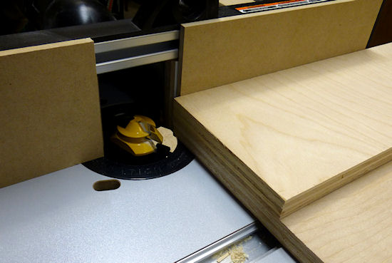
Using a second piece of plywood on top of the horizontal
work piece, to prevent chipping on the outer veneer. The second
piece should be aligned exactly with the fence side of the
board you're cutting; you can fasten it to the main board with woodworking
tape to keep it fixed in place throughout the cut. Note that
I'm set up for a shallow "first past" here, using MDF spacers
on the fence, as described below.
Using a second piece of plywood to prevent outer veneer chipping
on the vertical cut. I'm using a featherboard on the table to
keep the two pieces pressed against the fence through the cut.
Make the cuts in two passes
Your router probably comes with advice saying that you should always
make deep cuts with multiple passes. My router manual suggests going
no more than about 1/4" deep on each pass.
Well, if you look at this bit, it's quite a lot more than 1/4" deep.
Plus, it cuts a wide swath.
I've seen improved results by making each cut in two passes. The
lock miter bit's geometry lets us make multiple passes as long as
we do it by adjusting the fence depth (not the bit height - that
must stay identical for all passes).
The problem is that it's such a pain to get the fence aligned
perfectly that we don't want to touch it once it's set. But
there's an easy way to adjust the routing depth without moving the
fence: attach a little extra spacer in front of the fence. A thin
piece of MDF - 1/4" to 3/8" thick - works great for this. Cut pieces
roughly the same size as your fence halves, and attach it to the front
of the fence with small pieces of woodworking tape. After completing
the first pass on all pieces, remove the MDF spacers, and run the
pieces through again directly against the fence.
Pre-score the inner veneer to reduce chipping
My lock miter bit tends to make a nice clean cut on cuts that are
parallel to the grain. When making cross-grain cuts, though, the bit
can make a rather bad mess of the inside veneer, by knocking out lots
of little chips along the edge.
The obvious solution would be: don't do that! Unfortunately, you
can't avoid cross-grain cuts in a full-sized pin cab, because the
side walls are over 48" long. That forces you to orient the
side walls "the long way" when cutting up a 4x8 sheet of plywood,
which means that the front and back edges of the side wall will
necessarily be oriented perpendicular to the grain.
One way to deal with the inner veneer chipping mess is to just live
with it. It can look ugly, but it only happens on the inside face, so
it won't affect the exterior appearance. Plus, most of the length of
the inner corners gets covered up with the corner bracing wedges, so
most of it won't even be visible when you look inside the machine.
Another "deal with it" fix is to apply wood filler to cover up the
chipped edge. If you do that, I'd wait until after assembling the
cabinet, so that you don't accidentally fill in any of the miter cut.
I'd prefer to avoid the chipping in the first place, though. There's
a technique that can help at least mitigate it. The idea is to
pre-cut the veneer layer right along the line where the router bit
operates. The router bit will still chip the veneer, but the chips
should break off at the pre-cut line, so there should be no damage
beyond that point.
To do this, before routing, draw a line on the inside face,
parallel to
the edge, in from the edge by slightly more than 3/4" (the thickness
of the plywood). The lock miter cut has the same thickness as the
plywood, so this will be just slightly inside of where the bit will
touch the wood. Using an X-acto knife or sharp utility knife, score
the plywood along that line, all the way down the edge, cutting all
the way through the outer veneer layer (but just that deep). I'd use
a metal straight edge, clamped to the work piece along the cut line,
so that you can guide the knife by holding it against the straight
edge.
Important: Only do this on the face that goes on the
inside of the cabinet. Don't cut up the veneer on the outside -
the whole point of the lock miter is to make that look pretty by
avoiding any seams or cuts on the face.
Handling the work piece for the vertical cuts
The design of the lock miter bit requires running half of the
pieces through the bit vertically - standing them on end and
holding them against the fence, rather than laying them on flat
on the table. This is a challenge for tall pieces, because
the fence on most router tables is only a few inches tall.
It's difficult to keep a tall piece from wobbling, which
can make the cut uneven and damage the edge.
The way I arrange the pieces, the side walls get the vertical
treatment. So we have a 51" tall piece held vertically against a 4"
tall fence - not exactly easy to manage. I haven't found any way to
avoid this step, but I can at least suggest some extra tooling that
helps a bit. The idea is to build a "sled" that holds the work piece
in the awkward vertical position, so that you don't have to do that
entirely by hand. You clamp the work piece to the sled, and then you
slide the sled across the router table.
This "sled" is something that you can either buy or build yourself.
This is a common enough woodworking problem that there are a couple of
retail options available - search for "vertical router sled". But you
might be better off building one, because the retail options I've seen
aren't beefy enough to hold pieces as big as a pin cab side panel.
It's actually a pretty easy project to build. I'll outline the
design I used below.
My plan isn't especially clever, and there's no need to follow it
exactly. All that's important is the basic shape and approximate
size. The two main things to pay attention to are (1) making the
corner joint square, so that the work piece is kept at 90° to the
router table, and (2) making the vertical part tall enough to keep the
work piece steady. The whole contraption needs to be solid enough
that nothing sways or wobbles while you maneuver it through the
router.
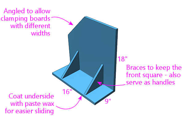
Everything is 3/4" plywood, including the triangular braces.
I routed shallow 3/4"-wide dados for the braces and glued them.
The seam between the front and bottom pieces is a lock miter
join made with my lock miter bit, and it's also glued.
The exact dimensions aren't important, but here's why I chose
the ones I did. The width is enough that I can use an F-clamp
on each side with the wide end (23½") of a cabinet side wall.
The height is more or less arbitrary, but this is enough
contact area to keep a 50"-long cab side wall steady once it's
clamped down. The depth is about the same as
the depth of my router table to the fence - anything longer than
that would just overhang in front and add useless weight.
Note that the join between the front and bottom pieces is a good
candidate for a lock miter, since you want this corner to be as square
as possible. You'll still need bracing, and the bracing alone should
be sufficient to keep everything square, so other joins are fine too.
But it makes a good practice project if you want to try out the
lock miter procedure before applying it to your pin cab.
Summary of recommendations
- Build a simple micro-adjuster for your router fence, to make precise fence positioning easier
- Set up the router bit first by height, then by fence position, using a series of test cuts and compensating adjustments to get the bit perfectly centered by height and fence depth
- After adjusting the bit and fence positions, test-build one corner using scrap material to verify that everything is aligned perfectly
- Aim for perfect corner alignment, because the error in each corner will result in twice that error in the overall cabinet width, which could affect the fit for the lockbar and TV (plus, perfect alignment will make the corners look perfect)
- Do the routing in two passes, with the first pass 1/4" to 3/8" shallower than the final pass; make the shallower first pass by using a temporary spacer in front of the fence
- Every time you run a board through the router, press another (sacrificial) board firmly against it on the outside face (the face away from the router bit) to prevent chipping on the outer veneer
- Before making a cut on an edge that's perpendicular to the grain, score the inside veneer with an X-Acto knife, just beyond the miter cut zone (so just slightly more than 3/4" from the edge), to reduce chipping on the inner veneer
- When making the vertical cuts, use a "sled" to keep the work piece square against the fence
