99. Accelerometer (Nudge) Setup
The KL25Z has an on-board accelerometer, which is a sensor that
measures the amount of acceleration applied to it. With a little
classical Newtonian physics, we can use acceleration measurements to
infer related information about the physical motion of the pin cab,
which we can feed into a physics simulation like Visual Pinball so
that nudging the cabinet can translate into a suitable effect on the
game.
Analog acceleration sensing adds a whole new kind of "control" to
pinball simulation, on par with real flipper buttons and mechanical
plungers. Physical interaction with the game via subtle and
not-to-subtle nudges is a huge part of real pinball that's completely
lost in desktop pinball. Desktop pinball tries to make up for it with
a "nudge key" that you can press, but that's not even close to the
real thing; it's like trying to replace the feeling of throwing a ball
with a button labeled "throw ball". The physical interaction you have
with a real pinball machine is automatic, subconscious, intuitive, and
the effect on the game is proportional and directional. A pin cab
with an accelerometer brings that same mode of interaction to virtual
pinball.
The KL25Z's accelerometer is built-in, and the Pinscape software uses
it by default to send readings to the PC. So there's very little to
set up on the controller side, other than physically installing the
KL25Z to take best advantage of the sensor. There are some options
you can set to fine-tune the input, though. And there's a small
amount of work needed on the PC side to configure pinball programs to
use nudge input.
This section is specifically about setting up Pinscape nudging. You
might also want to take a look at Nudge & Tilt, which looks at the
subject more generally.
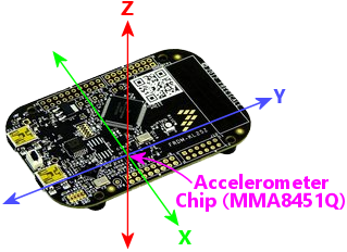
Positioning the KL25Z
The KL25Z's accelerometer is a three-axis type - it measures
accelerations side-to-side, front-to-back, and up-and-down. The
accelerometer chip is mounted on the KL25Z board so that the axes
align with the plane of the board.
To take the best advantage of this, we want to align those native axes
on the device with the axes of the cabinet, so that it's easy for the
software to translate the sensor readings from the device to the
motion of the cabinet. Specifically, the KL25Z board should be
roughly flat on the floor, and it should be square with the front and
sides of the cabinet.
"Square" with the front and sides means that the sides of the board
are parallel with the corresponding cab walls. That makes any of the
following orientations work (viewing the main cabinet from directly
above):
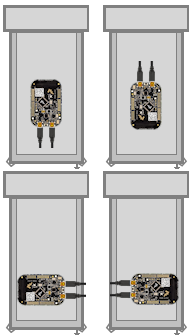
So that tells us how to orient that board. The exact placement within
the cabinet is a little more flexible. To a certain extent, it
shouldn't matter too much where you place it, because the board will
always move with the cabinet no matter where you put it. But the
cabinet's motion has some subtleties because of the way it sways on
the four legs, so I think it's best to locate the board close to the
front, roughly centered side-to-side. That'll place it closest to
where you're actually applying the nudge forces, so it should make it
pick up motions in the same directions as your nudges, or at least
as close as possible.
Finally it's very important to tightly attach the KL25Z to the cabinet
floor. It should be secured to the cabinet so that it moves exactly
as the cabinet moves. It shouldn't have any play that lets it slip
around on its own; you want it to precisely track the motion of the
cabinet. If you're mounting the KL25Z stadalone, attach it with a
couple of screws through the mounting holes near the USB connectors,
and make sure all four rubber feet are firmly planted. If you're
using the expansion boards, the KL25Z plugs in via pin sockets that
are a good tight fit, so you just have to make sure the main board
itself is securely installed on standoffs.
To summarize:
- Place the board flat on the floor of your cab
- Top side facing up (the side with the IC chips)
- Square with the sides, in one of the four orientations shown above
- Close to the front of the cabinet
- Roughly centered side-to-side
- Mounted securely so that it moves precisely as the cabinet moves
Config Tool nudge setup
The Config Tool has a few settings for the accelerometer that you can
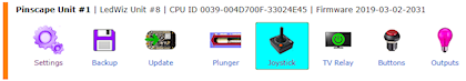
configure. To edit settings:
- Launch the Pinscape Config Tool
- Click the Settings icon for your device
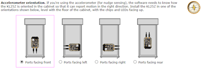
- Scroll down to the Accelerometer orientation section.
The most important thing to set here is the device orientation. Select
the radio button that matches the orientation of the physical device.
Dynamic range: this setting lets you change the maximum
acceleration that the device can register. There's a trade-off: a
wider dynamic range also means lower precision (the ability to
distinguish small differences in degree). The KL25Z's accelerometer
chip can be set to a maximum range of 1G, 2G, 4G, or 8G (meaning
N times the acceleration due to Earth's gravity). The 1G
setting has the best ability to distinguish fine shades of differences
at small accelerations, down to about 1/10000 of a "G", but any actual
acceleration higher than 1G (about 10 meters per second) will just
read as the maximum 1G. 8G is at the other extreme: it can
distinguish strong accelerations up to 8 times Earth's gravitational
acceleration (which are very strong accelerations indeed), but at the
low end can only distinguish to about 1/1000 of a "G".
In my opinion, the high-precision 1G setting is the best option for
pin cab. A 1G acceleration is pretty strong in this context, and I
don't see any practical need to distinguish nudges that are even
stronger than that. We're better off with the finer gradations of
subtle nudges that this setting can distinguish.
Auto-centering: If you could mount the KL25Z perfectly flat in
your cabinet, it would read "zero" on the X and Y axes all the time
naturally. If you have even a slight tilt, though, Earth's gravity
will register as a slight constant pull on these axes. Since this is
practically impossible to eliminate in the physical mounting, the
Pinscape software compensates for it by subtracting out any constant
acceleration on either axis. This compensation is called
auto-centering.
The auto-centering option is enabled by default, with a default
interval of 5 seconds. That means that any time the accelerometer
hasn't been registering any significant motion for 5 seconds, the
firmware will take the average reading over that period to be the true
rest position of the physical device.
You can change this to disable centering entirely, or to change to a
longer or shorter period. If you disable auto centering, you can use
the joystick viewer in the Config Tool to manually re-zero the
readings at any time.
I'd recommend leaving auto-centering enabled. The true physical
orientation in space of you pin cab will inevitably change slightly
over time, as a natural consequence of your pin cab shifting on its
footings. The KL25Z accelerometer is so sensitive that it'll pick up
these slight shifts. If you don't allow the software to compensate by
auto-centering frequently, you'll see a constant small bias in the
readings, as though you were constantly nudging the machine slightly.
The constant compensation provided by the auto-centering software
keeps these biases from developing.
Testing nudge input
The Config Tool has a built-in viewer/tester for the joystick
interface.
- Launch the Pinscape Config Tool
- Click the Joystick icon for your device
That brings up the joystick viewer window:
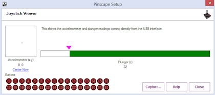
This lets you view the information that the device is sending to
Windows, to verify that the USB joystick interface is working properly
and that the accelerometer, plunger, and button inputs are working as
expected.
The little diagram at the left labeled "Accelerometer" shows you the
current nudge readings. The little crosshairs in the middle
represents the accelerometer reading in 2D space; up/down corresponds
to the front-to-back direction on your cabinet, and left/right
corresponds to left/right on your cabinet.
Check the orientation:
When you give your cabinet a push from any direction, you should see
the crosshairs jump briefly in the same direction as the force you
applied. Push the cabinet from the front, and the crosshairs should
briefly deflect upwards; push from the left, and the crosshairs should
deflect to the right.
If the crosshairs move in the wrong direction when you nudge the
cabinet, go back and check the device orientation setting to make sure
it matches the way you positioned the KL25Z in the cabinet.
Button inputs: The red circles at the bottom represent the
joystick buttons. These don't represent the physical button
inputs on your KL25Z - they're strictly the joystick button presses
that Windows sees through the joystick device interface. If you
programmed a button to send a keyboard key instead of a joystick
button, you won't see anything light up in the joystick viewer when
you press the button.
Windows calibration = bad
Windows has its own joystick device calibration procedure, which you
get to via the Windows control panel called "Set up USB game
controllers". Don't use it!
Everyone always wants to run this. They see the calibration option in
Windows and think it must be there to help. It is there to
help, but only for real joystick devices. It's a disaster to
use with nudge/plunger devices, because they're not anything like real
joysticks. Nudge/plunger devices only pretend to be joysticks
so that they don't need separate device drivers.
If you accidentally ran the Windows calibration before you read this
warning (everyone does!), you'll need to delete the Windows calibration.
The Windows calibration will screw up the Pinscape readings and make
your nudge and plunger inputs act erratically. Fortunately, they
made it pretty easy to reset the unwanted calibration data:
- Open the "Set up USB game controllers" control panel (press Windows+R, type joy.cpl, press Enter)
- Select the Pinscape device
- Go to the Settings tab
- Click Reset to Defaults
Visual Pinball setup
VP can use accelerometer input for simulated nudging. This isn't
enabled by default; you have to adjust some settings in VP to get
it working.
For instructions, see "How to configure VP for an accelerometer" in
Nudge & Tilt.
FX2/FX3 setup
Pinball FX2 and FX3 can also simulate nudging using an accelerometer,
but they don't use the joystick interface that Pinscape provides.
Instead, they require input through the XBox controller interface.
To bridge the gap, there's a program called
x360ce that can make a
joystick device emulate an XBox controller. That can reportedly
be used to make Pinscape nudging work in FX2/FX3.
I don't use this in my own system, so I don't have any details about
how to set it up. I anyone wants to write up instructions, I'll
be happy to include them here.
Conflicts with other joystick devices
Windows is happy to let you attach multiple joysticks to your system
at the same time, and doesn't have any trouble telling them apart.
However, not all applications are so accommodating. Some people have
run into conflicts between the Pinscape device and other joysticks or
joystick-emulating devices.
There are two main ways to deal with conflicts:
- Temporarily disable one of the devices when running applications where the conflicts occur
- Switch one or the other device to use different "axis" assignment for their data input
These techniques are described in more detail below.
Temporarily disabling a device
Many of the Microsoft software development kits (SDKs) include a tool
called devcon, which lets you temporarily enable and disable
individual devices. This can be a good way to deal with a conflicts
with another device that you only use with certain applications. That
is, you simply disable the other device when you're not using the
specific applications it's needed for.
For example, one person on the forums reported a conflict with a
special arcade controller device he only uses with certain video game
programs. The arcade device was creating a conflict with the Pinscape
device in Visual Pinball. But he didn't actually use the arcade
device with Visual Pinball, so the simple solution was to disable it
when Visual Pinball is running, eliminating the conflict in VP.
Installing devcon: The program comes with the Windows SDK,
which you can download from the Microsoft site separately or as part
of Visual Studio. You might also be able to find a plain devcon
download with a Web search, although I don't think Microsoft makes
it officially available separately from the SDKs.
Identifying the device: To disable a device with devcon,
you need to know its USB ID. devcon itself has a way to list devices
and their IDs. From a CMD prompt, go to the folder where you installed
devcon.exe and run this command:
devcon listclass HIDClass
That will show you a list of devices with their cryptic internal ID
strings on the left, and a device description on the right. The only
problem is that the device descriptions aren't very specific; they're
mostly vague things like "HID-compliant game controller". I think the
easiest way to figure out which one corresponds to your device is
the differential approach:
- Plug the device in
- Run the devcon listclass HIDClass command
- Unplug the device
- Run devcon listclass HIDClass again
- Compare the lists - the item(s) missing from the second list represent the device you just unplugged
Disabling the device: Once you've figured out which cryptic
ID string corresponds to your device, you can disable it as follows:
- Open a CMD prompt window in Run as Administrator mode (necessary because we're messing with device drivers)
- Go to the folder where you installed devcon.exe
- Type devcon disable "@xxxx", where xxxx is the full ID string from the "listclass" list
Re-enabling the device: Same procedure as above, but replace
the devcon disable command with devcon enable.
Automating it: You can automate the disable-enable procedure
by putting it into a .BAT script. However, keep in mind that you'll
have to run the .BAT script with "Run as Administrator" mode.
Axis settings
Another way to deal with conflicts is to tell Pinscape to report its
input on a different set of axes than it normally uses. This can
be useful if you're getting conflicting readings on the two devices
in a program that can't distinguish between different joysticks,
such as Visual Pinball.
Most joystick devices send their input to Windows via the main
joystick position axes, known as the X and Y axes. That's how
Pinscape normally sends its accelerometer inputs. There's also a
third standard joystick axis, called the Z axis, that Pinscape uses
for plunger input.
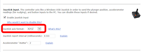
Pinscape has an option to switch its inputs from using the X-Y-Z axes
to a separate set of axes, called the "R" axes - Rx, Ry, Rz.
The axis assignment change can be made in the Config Tool's Settings
page, under the Joystick section:
In case you're wondering, the "R" stands for rotation. In a real
joystick, the R axes are used to report twisting motions on the stick.
For Pinscape purposes, it doesn't really matter what the "R" axes were
designed for; we just use them as an alternative way to send the same
inputs.
The Rx-Ry-Rz setting can work around conflicts in VP with other
joysticks that use the X-Y-Z axes. VP can't distinguish between
joysticks, but it can distinguish the different axes.
If you do change Pinscape to report readings on Rx/Ry/Rz, you have to
update the joystick input settings in VP and other programs to match.
VP will normally look for input on the X/Y/Z axes, so if you change to
Rx/Ry/Rz, you have to tell VP to look there instead.
The downside of using Rx/Ry/Rz axes is that some pinball programs are
either hard-coded to use the Z axis for the plunger, or can't use the
"R" axes at all. Future Pinball can't use the R axes at all, for
example. You'd lose compatibility with such programs if you moved
Pinscape to Rx/Ry/Rz. So I always recommend using the default X/Y/Z
axis settings whenever possible, and only changing to the "R" axes as
a last resort when you have a conflict with another device that you
can't resolve in any other way.
Note that Pinscape only lets you change to the "R" axes as a group.
Both the plunger and nudge inputs have to be on the same axis type.
