68. Circuit board assembly tips
Assembling a circuit board can be a little intimidating if you haven't
done it before, especially one with as many parts as the Pinscape
expansion boards. But remember that the whole point of a printed
circuit board is to make it easier to build a circuit. Ideally, a PCB
turns circuit assembly into a paint-by-numbers project.
Order of assembly
For most circuit boards, the Pinscape boards included, the order of
installing the parts really doesn't matter. Most PCBs have simple
flat layouts, without any parts layered on top of others.
The only thing I'd add is that it can sometimes be a little easier if
you start with the smaller parts and save the larger ones for last,
especially the taller ones that stick out the most. A couple of
taller parts close together can create a little valley, where it might
be harder to see the board markings for the parts that go in between.
Reading the markings on the board
The markings on the board are designed to make it easy to figure out
where each part goes. Each part generally has three things marked:
- An outline showing the "footprint" of the part on the board. This
is basically the way the part looks when installed if you look at it
from straight overhead.
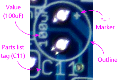
The outline often includes something to help you orient the part correctly. For example, a MOSFET's outline shows a thick bar on the side where the MOSFET's big metal heat-sink fin goes. You just have to line up the metal fin with the bar mark, and the part will be oriented properly. Similarly, a polarized capacitor's outline includes a "+" sign on the pad where the "+" leg goes.
- The part's "reference designator" (or just "designator") that identifies
it in the parts list, like R1 for a resistor or C7 for a capacitor.
To find the part to install, you just look up the designator in the parts
list, and the parts list will tell you exactly which part to use.
("Reference designator" seems to be the formal term for this. I realized when writing this material that I didn't know what this was really called before; I didn't have a term in my mind for it, and just thought of it as a label or name. This seems to be true for most people, and indeed, even the engineer-focused EAGLE software just calls it the "name". But "label" and "name" are too ambiguous when you're trying to talk about the schematics as a language; they could be easily confused for manufacturer part numbers, or part values like "100Ω".)
- A very concise description of the part, such as the Ohms value for a resistor, the uF (micro Farads) value for a capacitor, or the part number for an IC chip. This information is redundant with the designator, since you can use the designator to look up a more complete description in the parts list, but this is there as an additional guide. It's also a good idea to cross-check the value printed on the board against what you find in the parts list, to make sure you're really looking at the right labels. Sometimes two parts are so close together on the board that you can mistake one part's labels for another's.
For example, here are the markings you might see for a capacitor (in
this case, a polarized electrolytic capacitor, which has designated
"+" and "-" leads):
In the chapters that follow, where we go into more detail on each of
the common component types, we'll show you the specific types of
circuit board markings for each type.
Installing through-hole parts
All of the parts on the Pinscape expansion boards are "through-hole"
parts, meaning that they have wire leads that you insert through holes
in the circuit board and then solder into place.
Here's the basic procedure to install a through-hole part:
- Identify the part's footprint on the circuit board - the little outline showing where the part goes, which should contain all of the holes for the part's wire leads
- Determine the proper orientation (see the chapters on the various component types for more on how to do this for each type)
- Straight out or bend the leads on the part, as needed, so that they line up with the holes in the board
- Orient the part properly and feed the leads through the holes
- Try to seat the part as close to the circuit board as you comfortably can, without forcing anything. Parts should ideally sit flat against the board, so that they can't move around or bend once installed. But it's not necessary to force anything flush with the board; sometimes the leads won't quite bend enough and the part will sit a few millimeters above the board. That's fine.
- Holding the part in place (and keeping it from slipping back further away from the board), flip the board over and solder each of the leads to the pads on the bottom of the board
- After the solder cools, use wire snippers to clip off the excess length from the leads, so that there's no dangling wire past the solder joint
Soldering tips
- See the recommendations on soldering tools in Tools, including the recommendations on the solder itself. I've heard so many people on the forums say "I'm not a very good solderer", but what they often really mean (without knowing it) is "I'm using a crappy Home Depot soldering iron and crappy Home Depot solder". Those soldering irons are for casual home repair jobs, not delicate electronics work. Using them for circuit boards can be painfully difficult. You'll be amazed at how much your skills improve when you have the right tools.
- Keep a wetted solder-tip cleaning sponge handy while working. A soldering station should include this. Saturate it, then squeeze out the excess water. It should be thoroughly moistened but not dripping wet.
- Wipe the soldering tip on the sponge from time to time while working to keep it clean.
- Make sure the iron is at full temperature before you begin. A proper soldering station has a readout showing the temperature and a thermostat that holds the temperature steady.
- The default temperature setting on my Hakko soldering station is 750° F, and that seems to work well for PCB soldering work.
- When the iron is hot, coat it with a little bit of solder, just enough to flow over the surface. Wipe off any excess bead on the solder cleaning sponge.
- Most newbie solderers want to use the iron to melt the solder, and then try to drag the solder onto the parts. That's the wrong way to do it.
- The right way to do it is to heat the parts.
- Start by putting the two parts to be joined into the desired position.
- With the parts held together in this position, firmly press the tip of the iron against the point where the parts meet. Hold it there for several seconds to let the parts heat up. Then touch the solder to the junction point in the parts - not to the soldering iron, but to the join point. If the parts are hot enough, the solder will melt and flow over the parts, forming a bubble around the junction point.
- Don't use too much solder - just enough to flow over the parts and form a bubble.
- As soon as the solder flows over the junction, withdraw the soldering tip, but keep holding the parts together, keeping everything as still as possible, for about 5 to 10 seconds while the solder cools.
- Visually inspect the solder joint to make sure that the solder is confined to the desired area, and that it completely surrounds and covers the junction point. On a circuit board, it should stay within its solder pad, and it should form a nice little droplet shape covering the solder pad and wire lead. Make sure there are no gaps and that the wire lead is covered all the way around. Wiggle the part gently to make sure that the connection to the pad is thoroughly immobilized.
