29. Playfield TV Mounting
This section is about how to install the main TV - the one that takes
the place of the playfield.
This section tries to address the two big questions about installing
the TV. The first is where to position the TV in the cabinet, which
is as much a matter of aesthetics as of function. The second
is the engineering question of how to physically attach the TV to the
cabinet, once you've figured out where you want it.
Where to place the TV is one of the top questions that new cab
builders ask on the forums. It's one of those things that seems
self-evident at first glance, but has a lot of subtlety when you look
more closely. It's obvious that the TV has to lie on its back near
the top of the cab, but that doesn't quite answer the question, since
it leaves a few inches to play with to move the TV up and down and
front to back. Those few inches can make a lot of difference
aesthetically - it's that matter of what exact positioning is
ideal that raises all of the forum questions. This chapter surveys
the options and their respective pros and cons. I have some opinions
about what looks best, which I'll share, but I'll also try to give
equal time to the alternatives. I don't think there's a single right
answer, because everyone has their own priorities for their cab and
their own sense of what looks best.
After the survey of positioning alternatives, this section presents my
attempt at an all-purpose, universal TV mounting system. When I was
building my own cab, I found the TV mounting to be one of the more
challenging problems. The TV makers don't expect you to use a TV like
this, and the people who make pinball machines don't think of putting
a TV inside, so neither world gives us an example we can look to for
ideas, and neither world offers a ready-made hardware solution we can
apply. Every cab builder has always been on their own to work out
their own unique, ad hoc scheme. That always seemed like a waste of
energy to me; I've always thought there should be at least a basic
template we can follow. I think I've managed to come up with
something like that. This chapter provides a general-purpose design
that should be flexible enough to work with most TVs and most cabs,
using standard parts that you can readily buy. It's at least an
option to consider, and even if it isn't a good fit for your cab, it
might still give you some ideas to draw on. If you're looking for
even more ideas, at the end of the chapter, I'll outline a few
alternative mounting schemes that other cab builders have used.
We're assuming here that you've already picked out a TV to install.
If you're still shopping for a TV, there's a separate section with
advice about that, Selecting a Playfield TV.
Orientation
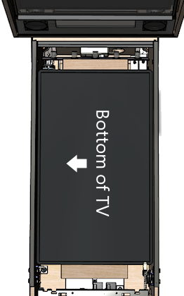
The playfield TV is always installed in "portrait" mode, to fit
the proportions of the cabinet. This represents a 90°
rotation from the standard way you view a widescreen TV.
But should it be 90° clockwise or 90° counter-clockwise?
Most virtual cab builders install it with the bottom of the TV
facing left in the cab:
In principle, it really shouldn't matter. Windows and all of the
pinball software should let you select whatever rotation you
want. But this is one of those cases where you can save yourself some
hassle by doing it the same way everyone else does it. There's still
a lot of older software in use in the pinball ecosystem, and some of
it might not be as adaptable as modern programs. I don't know of any
actual examples of software that will outright fail to work with other
rotations, but I know from helping people out with PinballY that
monitor rotation in general can cause configuration headaches,
especially with some of the commercial games.
Positioning options
Before we get to the mechanics of installing the TV, let's consider
exactly where you want to position it. To a first approximation, of
course, it goes "where the playfield goes". But a TV isn't quite the
same as a regular playfield, in either its nature or its size and
shape. So saying that the TV goes where the playfield goes is too
vague to constitute a plan. It leaves a couple of important
questions unanswered:
- Should the TV screen be flush with the top glass, or set in a bit like a real pinball machine's playfield?
- Should the TV be all the way at the front, flush with the lockbar, or should you set it back a few inches to make room for a plunger?
Judging by how often these questions come up on the forums, many
new cab builders agonize over these quite a bit.
I want to offer some thoughts about how to decide these questions.
Most new cab builders focus on how the placement will affect
playability. That's certainly the right priority. But the
thing is that playability actually won't be much affected, no matter
what TV positioning you go with. When you're playing, your eye adapts
to whatever setup you have, and before long you won't even notice it.
It's the same principle that makes the curtains around a movie theater
screen disappear once the film starts rolling. When you're playing,
it doesn't much matter where the TV is relative to the rest of the
cab. All of that disappears; your eye pays attention to the table.
This should be reassuring if you're been agonizing over the question,
because it means that you'll likely be happy with your cab's
playability no matter what you decide.
TV placement can make a big difference to the aesthetics of the cab,
though. Since playability isn't much of an issue, I think the
aesthetics are the better focus when making these decisions. In
addition, there are some functional considerations, since the TV
placement affects the space layout inside the cabinet. You might have
space constraints that decide some of these variables for you, before
you even get to think about how it'll look.
The dreaded plunger space conflict
See also "Positioning the plunger" in Plunger.
One of the key space constraints that affects TV placement is the
plunger. This is an issue because the most natural placement of the
TV and of the plunger put them into conflict: they both want to
occupy the same space.
The natural place for the TV is all the way at the front of the
cabinet. The natural place for the plunger is where it goes on
the real machines. The problem is that the plunger sticks into
the cabinet by about 3", so if the TV is all the way at the
front, it overlaps the plunger.
Why isn't this a problem on the real machines? In part, it's because
the plunger sits just above the playfield on a real machine, so
they're in different planes vertically and thus don't collide. In
addition, on the real playfields, they cut a notch out of the
playfield at that corner specifically to make room for the plunger.
That lets you lift up the playfield without hitting the plunger.
If we could cut a notch out of the TV, we could solve this the
same way, but that's not really an option. Our options all involve
moving either the TV or the plunger to make room for the other:
- Move the TV down a couple of inches to clear the plunger. I don't think I've ever heard of anyone doing this; I think it would put the TV lower than anyone wants it. In addition, you'd now have the problem that the plunger sticks out visibly above the TV, so you'd have to do something to cover that up.
- Move the plunger upwards far enough to clear the TV. I don't think this would be practical given the space constraints, but maybe you could make it work by sharing the work: move the TV down slightly and move the plunger up slightly. The plunger would stick out above the TV, so you'd have to cover it up somehow.
- Get rid of the plunger and use a Launch Ball button instead. The button doesn't create the same space conflict, so you can put it where the plunger would normally go and still have the TV all the way at the front. If you're not particularly attached to the idea of a plunger, this option has the additional upside that it's a big simplification overall, in that plungers are complicated on a virtual cab by their very nature. A lot of us would never consider doing without a plunger, though, since it's such an iconic pinball element.
- Move the plunger down to clear the TV. This requires moving it down by about 3". Some cab builders take this approach because it lets them both have a plunger and put the TV exactly where they want. I personally don't like the resulting look, though - it gives it a kind of weird home-brew vibe and makes it too obvious that it's not a real pinball machine.
- Move the TV further back to clear the plunger. This has the downside that it creates a gap at the front of the cab before the TV starts, which is unacceptable to some cab builders (who want the TV at the very front). In my opinion, though, a gap at the front isn't a problem, and you can even turn it into a virtue. For one thing, you can fill the space with something resembling the apron on a real machine. I think a 3D element like this adds some nice texture to the otherwise flat expanse of TV screen, and it's an opportunity for some added decorative graphics. For another, you're going to have a front-to-back gap somewhere, because a 16:9 TV simply doesn't have the same proportions as a standard cab. If you put the TV at the very front, the gap all ends up at the very back. I think it creates a more balanced look to split the gap between the front and the back.
Which option is best comes down to the priority ranking you would
assign to these three goals:
- I want a plunger
- I want the launcher at normal height
- I want the TV at the very front
Basically, you get to pick two of these, but you can't have all three.
Pick the two that you think are the most important, and that decides
the question for you:
- I want a plunger, I want it at normal height: then you should move the TV back. Personally, I rank these priorities highest, and this is the solution I like best.
- I want a plunger, and I want the TV at the very front: then you have to lower the plunger to clear the TV. I think that looks weird, but tastes vary.
- I want the launcher at normal height, and I want the TV at the front: then you have to dump the plunger and go with a Launch Ball button. I wouldn't want to forego the plunger, but not everyone feels as strongly.
Inset depth
The first decision you have to make about TV positioning is whether to
install the TV screen flush with the top of the cabinet, or recessed
into the cab by some distance. In the latter case, most cab builders
think of this in terms of placing the TV at the normal playfield depth
of the real machines.
These two main options are illustrated below, for the sake of
clarifying our descriptions, but I wouldn't try to make an aesthetic
judgment from the diagrams alone. The differences in question are
subtle enough that it's hard for an illustration or photo to capture
the full effect.
First, placing the TV flush with the top:
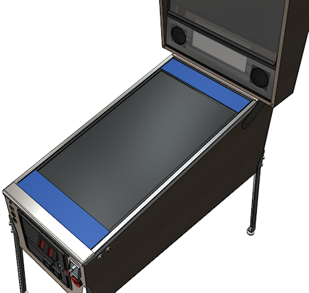
Playfield TV flush with the top of the cabinet, taking
the place of the top glass. The top glass can be added
if you set the TV back by about 1/4" to make room.
And second, recessing the TV into the cabinet to about the depth
of a normal playfield:
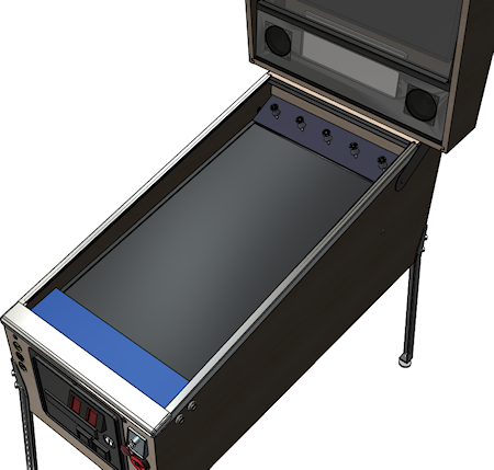
TV at roughly the same depth as a normal pinball playfield.
In comparing these for aesthetics, note that we've made the "filler"
areas at the top and bottom more conspicuous than they'd be in a real
build. You'll probably make these a darker color in your actual build
(probably black, maybe with some graphics decorations). We wanted to
make it obvious in the illustrations that they're not part of the TV
screen, which they might appear to be if we made them a flat black.
Pros and cons
Aesthetically, I have a strong preference for the inset version. I've
seen both setups in person, and I find the flush-top version to look
too much like a video game, with the whole top being a TV screen.
Setting the TV screen down into the cabinet makes it look more like a
regular pinball machine, and creates more of a 3D effect. It also
lets you add a raised apron at the front, which adds another 3D
element to contrast with the flatness of the TV screen.
Some people prefer the flush-top version on the theory that the
simulated pinball tables already depict a portion of the inset
depth. I don't find that reasoning convincing, because most of the
pinball programs let you adjust the point of view to show as much or
as little of the side walls on the TV as you want. The less the
better, as far as I'm concerned, because video images of the walls
take away TV space that could be used for actual playfield area, and
they don't look as realistic as real side walls.
In terms of playability, I don't think it makes any difference
one way or the other. For the most part, once you're into a game,
your eye only pays attention to the active playfield, and mostly
ignores the surroundings.
Functionally, each version has its advantages. The inset version
makes room for a flasher panel at the back, which I see as a major
plus, as well as LED strips along the sides. It also leaves
an air gap for cooling between the screen and the top glass (if you're
including top glass).
The flush-top version has the advantage that it rotates the screen
slightly closer to a head-on viewing angle. Everyone knows that the
picture degrades on many flat-screen TVs when viewed from too steep an
angle off to the side, so this might be a concern for some TVs.
However, I think a lot of cab builders get overly worried about this.
Keep in mind that the viewing angle difference between the "inset"
setup and the flush-top setup is only about 2-3°, and they're both
pretty far from head-on. I think on most TVs it will make little or
no difference. If you're concerned about it, test your TV from the
two angles and see if it makes a big enough difference to be the
deciding factor.
A second advantage of the flush-top setup is that it consumes a little
less vertical space in the cabinet. That's usually not a big deal one
way or the other in a full-sized cab, but the extra space might make a
bit difference in a mini-cab.
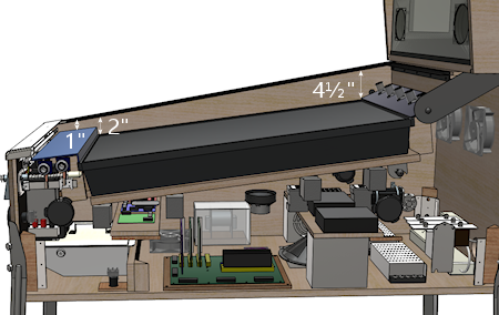
What is the standard real playfield depth?
If you're using an inset to simulate the playfield depth of the real
machines, what's the authentic distance?
We actually have a fairly large range to choose from, because the real
machines vary quite a bit, mostly by vintage. In the 1970s and
earlier, most machines had very shallow playfield insets: the
playfield surface was typically only about 1½" to 2" below the
top glass, all the way from front to back, and the top of the apron
was almost flush with the glass. In the 1980s, the depth started to
increase to make room for the three-dimensional features that became
common, such as ramps and two-level playfields. A mid-1980s machine
might have an inset of 3" at the front and 6" at the back. Note that
this generation started sloping the playfield relative to the top
glass, so that it had more headroom at the back, to allow for taller
ramps and other features. As the years went on, the 3D features got
even taller. By the 1990s, the playfield depth had increased to
around 4" at the front and 8½" at the back. It reached a
plateau at that point; the latest Stern machines tend to be about the
same.
Recommendations
I much prefer the "inset" style over the flush-top design
aesthetically, so that's my first recommendation. I'd only use a
flush-top design if you have to due to some kind of physical
constraint, like an oversized TV that can only sit on top of the side
walls.
Assuming you're going with the inset style, the depth and angle are
pretty flexible, since the real machines cover such a wide range. I
don't think you need to replicate the precise measurements of any
particular real machine - I think all you need to do to look "right"
is to maintain the general proportions. Specifically, I'd say this
means:
- the playfield should be set in by at least the height of the ball (about an inch)
- it should be angled slightly upward (about 5° to 6° relative to the floor)
- for WPC-style cabinets, the angle should be less than the angle of the top glass, so that the back of the TV is set in deeper than the front
- for older EM-style cabinets, the angle should usually be about the same as the top glass
In terms of looks, that gives us a pretty wide range to work with.
There is one practical consideration that I'd add: if you're using
an apron at the front and/or a flasher panel at the back, you'll need
to leave a little extra vertical space for those. Exactly how much
depends on how you want those features to look. For example, the
flasher panel can be horizontal, tilted, or vertical:
I personally like the tilted style best, but that's probably a matter
of taste more than anything else. In terms of space, a flat
flash panel only needs about 1¼" of headroom, for the height of
the domes. A tilted flasher panel needs more, depending on the angle;
I'd give it at least 2". A vertical panel needs at least an inch (for
the diameter of the domes), but you'd probably want to leave some
margin for visual borders as well.
To summarize my recommendations:
- Use the inset style
- Choose a depth based on the era your cabinet is based on:
- For a WPC-style cabinet, inset the playfield by about 2" from the top of the wall at the front and 4-5" at the back
- For an EM-style cabinet (1970s or earlier), inset by a uniform 1½" to 2", or as much as needed to make room for the flasher panel
Front-to-back positioning
The second decision you have to make about TV positioning is where to
put it front-to-back. Assuming you're building a cabinet to something
like the standard proportions, the playfield area will be longer than
a 16:9 TV, so there will be some leftover space front-to-back. The
extra space typically amounts to about 6" in a standard-body cab.
The question here is whether to split the extra space between the
front and back ends of the cabinet, like this:
...or to put it all at the back, like this:
In either case, some space at the back is actually nice to have, in
that it's a natural place to put a flasher panel (see
Flashers and Strobes) or an LED matrix (Addressable Light Strips).
Space at the front can also be functionally useful, because of the
potential conflict between the TV and the plunger, as described in
"The dreaded plunger space conflict"
above. So you might have already
decided to set the TV back to make room for the plunger.
Even if you're not forced to set the TV back by your plunger setup,
I'd still consider it a valid aesthetic choice. Splitting the extra
space front and back makes for a more balanced look, in my opinion,
and I like the way an apron-like area in the front adds a 3D element.
But many cab builders are very attached to the idea of having the TV
all the way at the front, so that might be a higher priority for you.
For what it's worth, I also thought that way when I was planning my
cab layout, and only reluctantly accepted a front gap after
determining that it was the only workable solution for the plunger
conflict. But as it turned out, I think I'm happier with the
apron-style setup than I would have been with no front gap.
De-case it or not?
When I built my virtual cab, it was common practice to "de-case" your
playfield TV, meaning that you disassembled the TV and discarded the
outer plastic case, keeping only the bare LCD panel and circuit
boards. The point was to remove the bulky exterior bezels around the
perimeter of the screen, which at the time were often quite wide. On
many TVs, the case extended a couple of inches below the bottom of the
viewable screen area to make room for buttons and input jacks. That
was a huge problem for cab builders, because we use the TVs in
"portrait" mode - turned sideways. So if there was a wide area at the
bottom of the TV, it became a wide area along the left or right side
when we turned the TV sideways. Obviously quite undesirable in a cab.
The solution was to get rid of the case. After de-casing, you'd
normally be left with a bare LCD panel. That still had a bezel of a
sort, in the form of a metal frame holding the panel together, but it
was typically fairly thin - maybe 1/2" wide - and the same on each
side.
De-casing is no longer common. There are two big reasons for this.
The first is that it's simply not possible for many newer TVs. Older
LCD TVs were built around self-contained panels, so you could fairly
easily open up the case and extract the panel. The panel was usually
a sealed unit, so it would stay in one piece when you removed it.
With many newer TVs, it seems that the TV is the panel. That
is, there's no longer anything like a separate component inside that
you could call "the panel"; instead, the exterior plastic case serves
as an exoskeleton that holds the parts of the panel together. If you
take off the case, you're left with a bunch of loose parts that won't
stay together on their own. Several people on the forums have
reported discovering this the hard way.
The second reason is that there's no longer as much of a need to
remove the case (even if you could). The whole motivation in the old
days was to get rid of the bulky exterior bezel surrounding the
viewable screen area. Newer TVs generally don't have that bulky
exterior in the first place. The exterior bezels on newer TVs are
usually as minimal as the interior frames were on the old de-cased
panels, thanks to the exoskeleton design. Newer TVs also don't tend
to have any buttons or input jacks anywhere on the front, so there's
no need for one side to be any wider than the others.
I'd only consider de-casing a newer TV if you can find information on
the Web about how to safely de-case the particular model you're
using. In the absence of reliable information on the specific model,
I'd plan on using the TV with its case intact. Take this into
account when shopping by looking for a TV that has minimal bezels.
Use the full case width stated in the spec sheet when figuring which
TVs will fit in your cab. If you're designing a cab around a selected
TV, figure the cab size based on the TV's case width.
Side trim
Unless you're building your cabinet to a custom width to exactly fit
your TV, you'll probably have some space left over side-to-side
between the TV and cabinet walls. Most people want to hide the gaps
as much as possible.
The best option I know of is to use black acrylic strips, custom-cut
to the required width.
You can have acrylic cut to a custom size by a local plastics store or
hardware store. If you're on the west coast, check for a local
TAP Plastics store.
You can also order custom plastic online at
Ponoko.com. They have two
drawbacks compared to a local shop: you'll have to pay for shipping,
and their maximum sheet length is about 31". A TV in the
standard-body size range will usually be about 36" wide. You can deal
with that by splitting the trim along each side into two pieces, but
that leaves a seam.
You attach the trim on top of the TV's side bezels using a strong foam
tape.
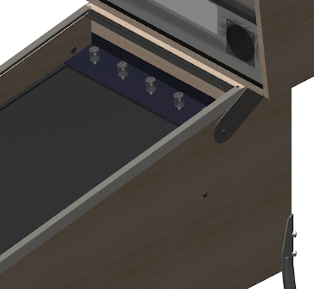
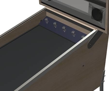
Tilt-up mounting
In a real pinball machine, the playfield is mounted on a hinge at the
back, so that you can tilt it up like the hood of a car.
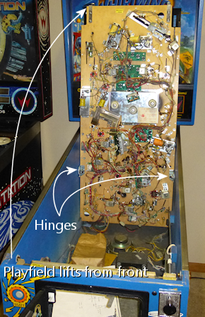
This gives you easy service access to the interior of the machine.
There's nothing to disassemble, no fasteners to remove; you just take
off the lockbar and lift the playfield.
The reason we're looking at how the real machines do this is that we
can use it as a model for how to mount the TV in a virtual cab.
Access to the interior is just as important for a virtual cab. And we
can copy more than just the idea - we can adapt the mechanisms used in
some of the real machines. As I've said before, it often pays to look
at how the real machines accomplish things, because they came out of
decades of experience solving some of the same problems.
How it works in a real machine
The exact mechanism used on the real machines varies by manufacturer
and vintage. The particular version that I think translates best
to a virtual cab is the one used in Williams machines from the 1980s
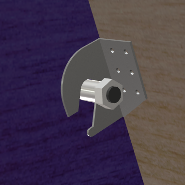
and early 1990s. They used a simple but clever scheme, with a hinge
bracket attached to the bottom of the playfield, and a pivot bolt
fastened to the side of the cabinet.
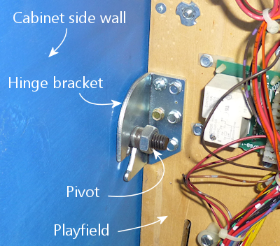
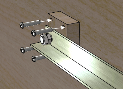
Here's a more schematic view:
Taking away the side wall of the cab for a moment, here's how this
all fastens to the cab:
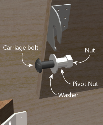
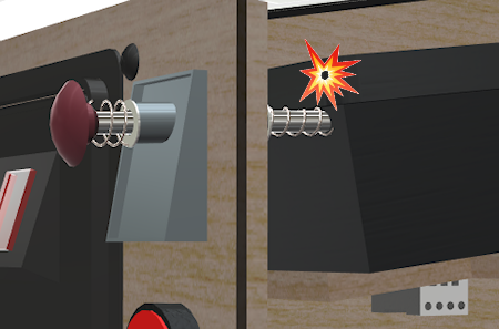
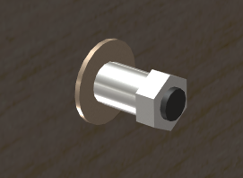
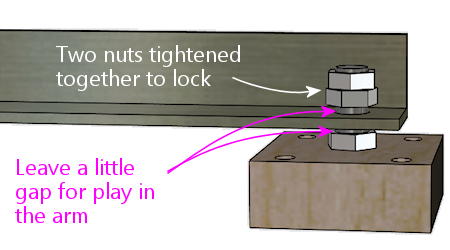
The main fastener is the carriage bolt. (That's a type of bolt with a
smooth round head on the outside, without any screwdriver slots. This
makes it visually inconspicuous on the outside.) On the inside, we
slip a pivot nut over the bolt. The pivot nut is basically a round
metal sleeve that threads onto the bolt; it provides a smooth pivot
point for the bracket. A conventional hex nut is added on the end to
hold lock the assembly in place.
The nice thing about using a carriage bolt as the pivot is that it
only intrudes into the cabinet by about an inch. It doesn't get in
the way of anything inside the cab for maintenance access.
Going back to the bracket, note how it's open at the bottom. The
bracket isn't in any way permanently attached to the pivot pin, like
it would be in a regular door hinge. Instead, the playfield bracket
just sits on top of the pivot. It's held in place by gravity (a
playfield is heavy enough that gravity does a very good job of it!).
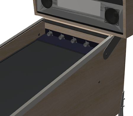
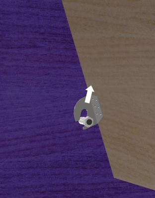
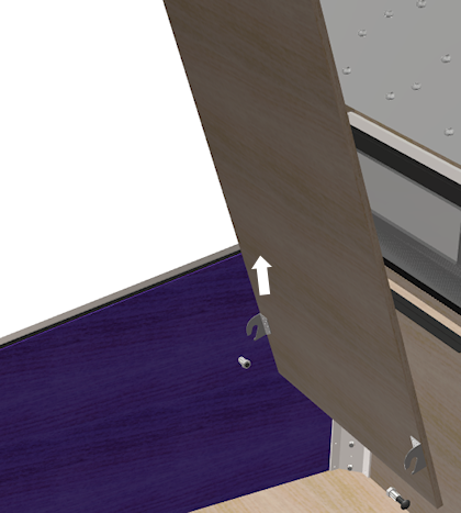
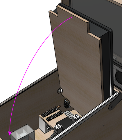
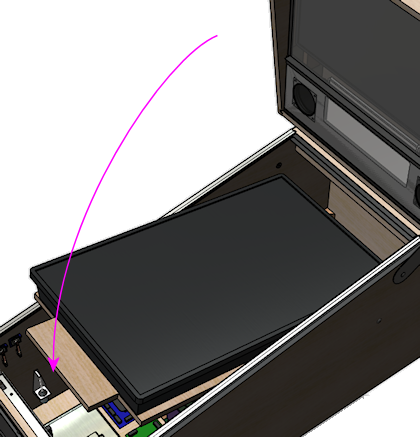
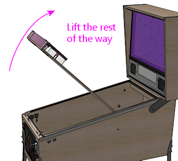
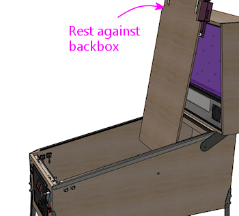
If you want to remove the playfield entirely, it's a simple matter of
tilting it up like this and then lifting it straight out of the cab:
That's the really clever thing about this arrangement. With this
simple mechanism, we get two levels of access, both without any
tools needed:
- For routine access, just tilt up the playfield (or TV in our case) like a car hood
- If you need to remove the playfield (TV) entirely, unplug the power and video cables from the TV and lift it out
There's a surprising third benefit to this design: it's fairly cheap.
Using the real pinball parts, it comes to about $20. It would be hard
to create a similarly functional mounting with generic parts from
a hardware store, and even if you could, it probably wouldn't be
any cheaper.
Adapting it to a TV
Here's my all-purpose plan for adapting this to a virtual cab TV. The
general design should work with virtually any TV and with any cab
size, although you'll have to adjust the dimensions if you're not
using the standard WPC cab size.
- Create a plywood base, approximately the size of a standard playfield
- Attach the TV to the plywood base using the VESA mounting holes on the back of the TV
- Attach the pinball playfield brackets to the back of the base, just like they'd attach to a real playfield
- Attach the pivot nuts to the side walls of your cab, just like they'd attach to a real cab
- Drop the TV into the cab so that the brackets rest on the pivots, just like in a real cab
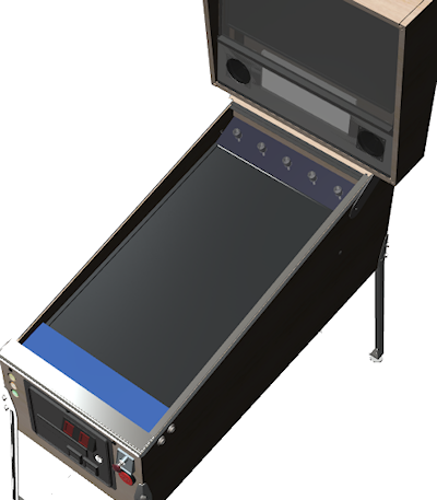
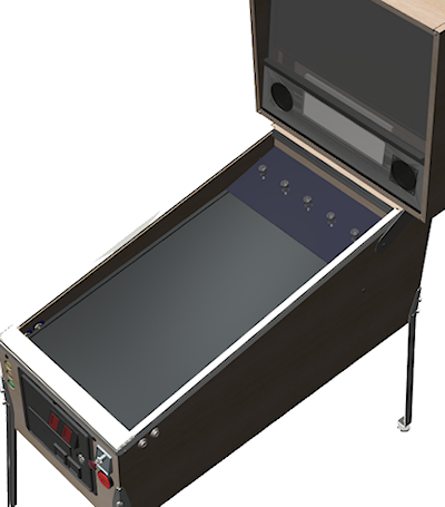
When I say this plan is "all-purpose", I mean not only that it'll fit
different cab sizes, but that it'll work with any of the TV placement
options we've discussed. The diagrams show the setup I like best,
with a recessed TV set about midway front-to-back, with an apron at
the front and flasher panel at the back. But that's all for the sake
of illustration. The plan doesn't force any of those decisions on
you. It's flexible enough to work with many alternative setups:
- You can put the TV anywhere you like front-to-back. The plan uses a platform that holds the TV, running most of the length of the cab. You can place the TV anywhere you like on the platform.
- You can use this plan for a flush-top TV or a recessed TV. It's just a matter of where you position the hinge pivots.
- You don't have to use an apron or flasher panel with the plan. They're optional add-ons.
At each stage in the plan, I'll point out where your TV placement
design decisions come into play.
Parts
The easiest way to implement this design is with the real pinball
parts. The playfield brackets in particular are highly specialized
for this job; there's no generic equivalent. Fortunately, the parts
aren't expensive.
- Playfield holder bracket (left side), Williams/Bally 01-8726-L-1
- Playfield holder bracket (right side), Williams/Bally 01-8726-R-1
- Pivot nut, 7/16", Williams/Bally 02-4244; or 1/2", 02-4329 (quantity 2)
- Carriage bolt, 3/8"-16 x 1-3/4", black, Williams/Bally 4322-01123-28B (quantity 2)
In addition, there are some generic hardware parts, which you can
get from the pinball vendors or from a hardware store:
- Washer, 3/8" x 1" outside diameter (quantity 2)
- Hex nut, 3/8"-16 (quantity 2)
Finally, the mounting base and bolts:
- Good-quality 1/2" to 3/4" hardwood plywood (at least 2' x 4')
- M4 or M6 bolts as needed for your TV's VESA mount, 20mm length for 1/2" plywood, 30mm length for 3/4" plywood (quantity 4)
- Washers to go with the M4/M6 bolts (quantity 4)
The plywood base isn't going to be visible, but you should use
high-quality material anyway, because it needs to be strong and (maybe
more importantly) flat. The cheaper stuff they use for framing and
roofing doesn't tend to be all that flat. You want a nice flat piece
here so that the TV sits securely and doesn't wobble due to a warped
base.
Don't use particle board or MDF. Particle board is terrible at
supporting point weights, as we need to do at the hinges. It also tends
to sag over time.
Strength and weight
The pivot setup puts all of the TV's weight on the hinges when the TV
is raised, so it's reasonable to ask if the hinges are strong enough.
We know that the mechanism has a proven track record on the real
machines, so as long as we're not asking more of it in terms of weight
than the real machines do, we should be safe. I'd estimate that a
pinball playfield (assembled) is in the range of 50 to 75 pounds.
A modern TV in the 40" range is under 20 pounds, and the plywood
should be around 10 pounds. That leaves us with a weight budget of
about 30 additional pounds for other features that we might want to
attach - apron, flasher panel, and solenoid devices to simulate
flippers and bumpers.
So I think we're very safe! The only thing to be concerned about
might be a full slate of unusually heavy feedback devices. Contactors
wouldn't be a problem by any means as they're quite light. Real
pinball mechanisms are heavier, though (they're the main reason the
real playfields are so heavy), so if you're using those you might want
to keep track of how much weight you're adding at each stage. You
can always split things up so that some of the devices are mounted
to the TV platform and others are mounted in the main cabinet.
How to install
Here's the step-by-step procedure for building and installing the
universal, all-purpose tilt-up mounting system.
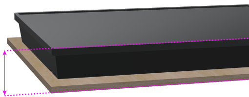
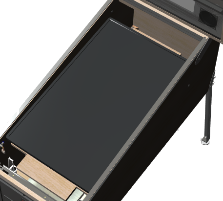
Step 1: Measure your TV's depth. Place the TV on its back on the
plywood sheet you're going to use for the base, making sure it's flush
with the VESA mounting area, like it's going to be when installed.
Measure the height from the bottom of the platform to the top of the
TV.
This measurement will let us figure the alignment position of the
platform in the cabinet that will position the TV's screen surface
where you want it.
Step 2: Mark where the TV will go. Choose where you want
the TV to go in the cabinet, as described earlier in this chapter.
In particular, figure out the inset depth where you want the
TV screen surface to lie - flush with the top of the cabinet, or
set into the cabinet by some distance.
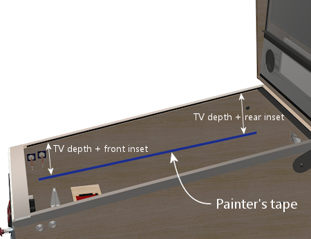
In your cabinet, measure and mark the positions where the bottom
of the platform will go towards the front and back of the side walls.
The front point should be right around the flipper buttons, and the
rear point should be around the rear shelf.
At each point, calculate the desired TV screen inset depth (the distance
you want between the top of the cabinet and the TV screen) plus the
TV-and-platform depth measured in Step 1.
For example, if you like my recommended inset of about 2" at the
front and 4" at the back, and your combined TV-and-platform depth
is 4", you'd mark a spot 6" below the top at the front and 8" below
the top at the back.
Once you mark the front and rear spots, mark a straight line through
the points with pencil or painter's tape. This will be the position
of the bottom of the platform.
Mark both side walls the same way.
Each stop will have to support about a quarter of the weight
of the whole assembly (the combined weight of the TV, plywood base,
and any feedback toys you attach to the bottom of the base).
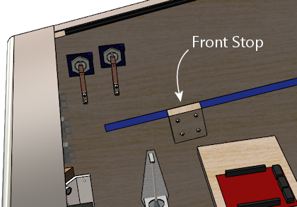
You can use a sturdy metal post or a wood block for each stop. It
only has to extend into the cabinet by about 3/4" of an inch to do the
trick, since we're going to make the plywood platform base almost as
wide as the cabinet. I'd suggest using a piece of 3/4" plywood cut to
a convenient size, say 2" x 2", fastened to the cab wall with
four #6 x 1¼" wood screws.
Align the top of each stop with the position where the bottom of
the platform will rest, as marked in the previous step. (If you
used painter's tape to mark the position, you might want to remove
it before installing the block on top of it!)
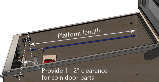
Step 4: Figure the length of the base. The base should
cover the area from about an inch or two behind the coin door
mechanisms, to about directly underneath the backbox shelf.
If you're using the standard-body WPC plans, the result should
be about 40".
Step 5: Create the plywood base. Cut the plywood base sheet as
shown below, making the following adjustments first:
- Adjust the width to equal 1/4" less than the inside width of your cabinet
- Use the overall length you calculated in the previous step.
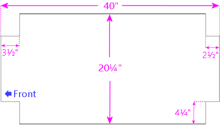
TV platform template for a standard-body WPC cabinet. Adjust
the length and width for your cabinet as described above.
The cutouts at the front are there to provide clearance around the
flipper buttons and plunger. They also make it easier to mount an
apron at the front, which we'll come to later. The cutouts at the back
are for mounting a flasher panel.
The shape shown is only a suggestion - it's really just the simplest
shape that fits the requirements. I wanted to provide something that
you can use "off the shelf", but at the same time I don't want to
imply that this shape is the only one that will work. Don't hesitate
to adjust it to fit any special requirements of your own. Just pay
attention to the core requirements that went into this design:
- It needs to fully cover your TV's VESA mounting area
- The front should come as close to the coin door as possible (while clearing the protrusions on the inside), so that you'll be able to reach in through the coin door and lift up the TV when you want to access the cabinet interior
- The area near the back where the hinge brackets are mounted needs to be at full width
- The area near the front where it'll rest on the front stops needs to be at full width
- Front cutouts are required to make room for the flipper buttons and plunger mechanism
- Rear cutouts aren't required, but are helpful for attaching a flasher panel
Step 6: Measure for the hinges. I'm a fan of using the
actual work pieces to make the measurements whenever possible, since
there's less chance of making a mistake reading the ruler, and less
accumulation of rounding errors. So now that we have the platform
ready, we can use it to figure where the hinges go.
This step will also give us a chance to test the fit, to make sure the
platform looks as expected and fits the cabinet properly.
Place the platform in the cab where you want it to be situated when
finished. Rest the front end on the front stops we installed earlier,
and hold up the back end, aligning the bottom of the platform with
the pencil line or painter's tape that marks where it goes.
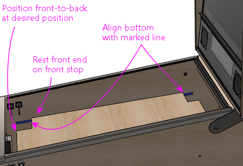
Judge the position mostly by the front: you want this to be within
easy reach through the coin door, so that you can use it to lift up
the TV when you want to access the interior, while leaving enough
clearance that it won't collide with the coin mechanisms and other
protrusions inside the door. Also check that the back lines up where
expected, right around the front of the backbox shelf. Exact
alignment isn't important.
Once it's in the right position, get out your pencil or painter's
tape and make another mark, this time making the position of the
rear cutout.
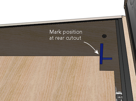
You can take the platform out, leaving behind the new rear marking.
Now we come to the question of exactly where to position the pivot
point. It should be pretty apparent that the vertical position is
purely determined by the desired TV depth. But the front-to-back
position doesn't have to go at a fixed point. It has to go somewhere
near the back to make the balance work, but beyond that, should
it go at the very back, or somewhere closer to the midpoint? Remember
from the picture earlier of the real pinball playfield that
they positioned it quite a ways from the back. And they
did that for a reason, which will become clear shortly.
I'm going to give you a one-size-fits-all location for the hinges, but
I also want to let you know how I came up with it, and explain the
trade-offs involved. You might want to check my work and figure out
if you want to adjust the location for your cab.
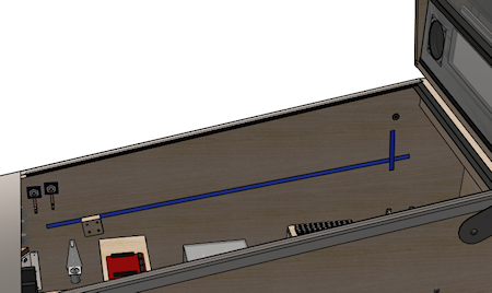
First, the one-size-fits-all location: put the pivot point forward
of the rear shelf by about the combined depth of your TV and platform,
plus 1/2":
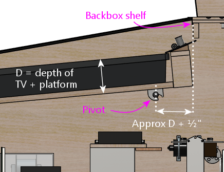
This is just a rule of thumb, so it might not be perfect for your
setup. But it should be pretty good for most cabs. The reason this
works is that it's just far enough forward to create clearance with
the backbox shelf to allow the TV to tilt up almost to the vertical.
Now to the details.
The pivot point is at the nexus of some conflicting geometric
constraints. On the one hand, a pivot point that's further forward in
the cabinet creates more clearance between the playfield and backbox.
On the other hand, the further forward the pivot point, the longer the
overhang at the back that has to dip into the cabinet, which means you
need more empty space within the cabinet to accommodate it.
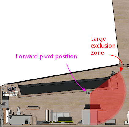
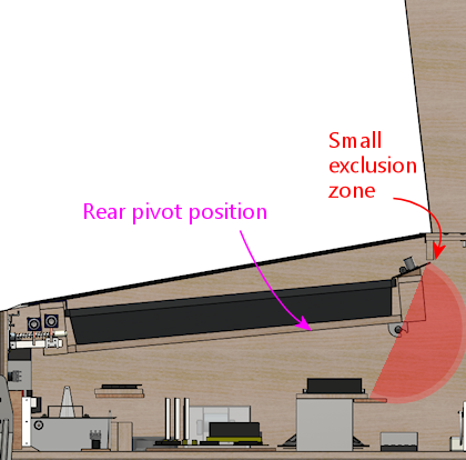
To illustrate, if we put the pivot point too far forward, we get lots
of clearance above, allowing us to lift the TV more than 90°, but
we create space conflicts in the cabinet below:
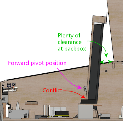
If we put the pivot point too far back, we leave plenty of room in the
cabinet below, but we can't raise the TV very far before it hits the
backbox shelf:
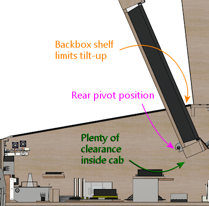
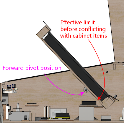
Note how the further-back position allows us to tilt the TV higher
than the further-forward position when we take all of the constraints
into account. But if we look between these two extremes, we can
actually do even better.
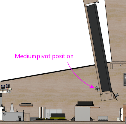
There's no solution where we're completely free of the constraints,
but there's a happy medium between the two extremes where we get the
best overall combined clearances, and the greatest overall tilt-up
angle. That's the good news. The bad news is that I can't give you
the magic optimal number for your cabinet. It's probably obvious from
the diagrams that the number will be different for every combination
of TV size, cab geometry, and what's installed inside the cab. The
optimal number for your cab is going to be unique to your cab. So
there are two ways you could approach this:
- Mock up your cab's geometry (with a cardboard model, say, or with a CAD program) and work out the optimal location by experimentation
- Pick a pretty-good-but-not-optimal location based on the rule thumb provided earlier
Even though I'm picky about these things, I think it might be just
fine to go with the pretty-good solution in this case. In my own cab,
I used a less sophisticated hinge mechanism that only lets me tilt up
the TV by about 60°, and while that's sometimes an obstacle, it's
more than adequate for most jobs. I think the pivot system I'm
describing here will do better than that even if you don't optimize
the pivot position perfectly - you should be able to get around
80° without trying too hard to find the perfect position. The
optimal solution will be slightly better, but I think there will be
diminishing returns; if the TV is in the way at 80° tilt, another
another few degrees won't get it out of the way completely. And
remember that this hinge mechanism also makes it easy to remove the TV
entirely, so tilting up the TV isn't the last resort for the rare
cases when you need unobstructed access.
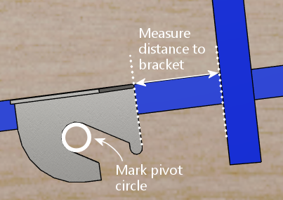
Step 8: Mark the bracket position. Using the distance to
the pivot figured above, hold the bracket against the side of the
cab, with its top aligned with the "bottom of the platform" line
marked earlier, and the pivot opening centered on the pivot distance.
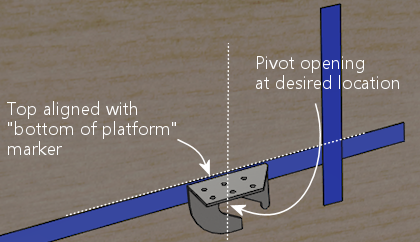
Make two measurements/markings, as illustrated below:
- Measure and record the distance between the "back of platform" and the edge of the bracket. We'll need this number when we install the bracket on the platform later.
- Mark the circle where the pivot goes. We'll need this location to drill the holes for the pivot bolts.
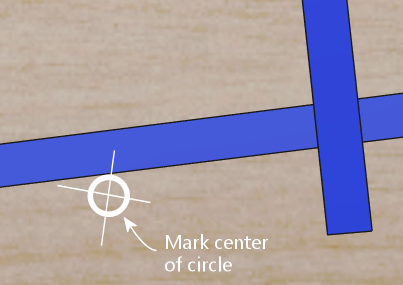
Remove the bracket and mark the center of the pivot circle. This
is the drilling location for the pivot carriage bolt.
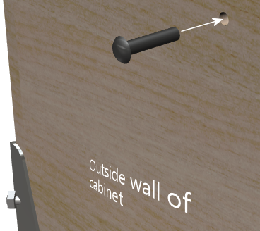
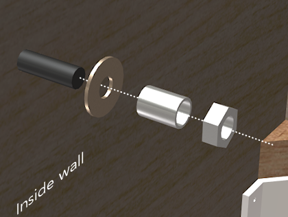
Step 9: Install the pivots. Drill a 7/16" hole in each side
wall at the marked pivot position. Insert a 3/8" x 1-3/4" carriage
bolt into each hole from the outside. Place a 1" diameter washer over
each bolt on the inside, then thread a pivot nut into each bolt and
tighten. Add a hex nut and tighten.
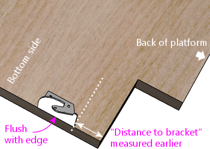
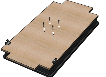
Step 10: Install the platform brackets.
Flip the platform over so that the bottom side is face up. Place
the bracket onto the platform, using the "distance to bracket" that
we measured and recorded in step 8, and aligning the outside edge
of the bracket so that it's flush with the edge of the platform.
Mark the locations of the three holes illustrated below.
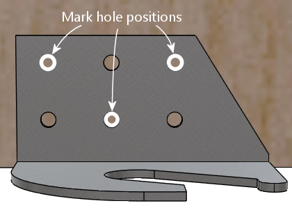
Drill holes for #6 machine screws at the marked positions.
Fasten the bracket to the base with #6 machine screws and nuts
in the drilled holes. Use #6 wood screws in the remaining three
holes to further strengthen the attachment.
(In terms of strength, this method of attachment should be at least as
strong as on the real pinball machines I've looked at. They use two
machine screws mated with T-nuts, plus four wood screws.)
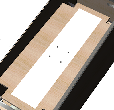
Step 11: Figure the TV position. You could figure the TV
mounting position on the platform by measuring and dead-reckoning, but
let me suggest a more direct approach that I think is a little easier.
What we'll do is create a template for the VESA drill holes, and
position the template on the platform using the TV itself itself.
That will let you see exactly what it looks like in place, and
fine-tune the final position.
To create the template, put the TV face-down, and stretch a strip of
paper over the back of the TV, covering the VESA mount area. You can
Scotch-tape together a few sheets of 8½-by-11 paper if you
don't have something big enough. Use masking tape at the sides and/or
front to hold the paper in place.
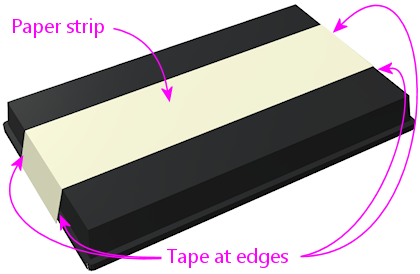
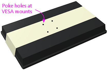
Locate the four VESA mounting holes on the back and poke holes in the
paper at those spots.
Install the platform in the cab, placing it on the hinges and lowering
it to the front stops.
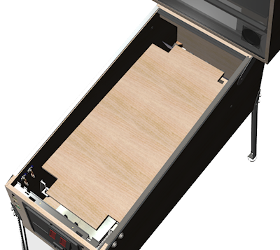
Now flip the TV over, and place it on the platform. Position it where
you want it to go when this is all done.
Once you're happy with the position, untape the template from the TV,
and tape it to the platform instead. Be careful not to let it move at
all while you're transferring it.
Use the holes in the paper to mark the positions of the VESA drill
holes on the platform. Remove the template.
Step 12: Attach the TV. Drill holes for the VESA mounting bolts
at the positions marked in the previous step. Drill 3/16" holes for M4
bolts or 1/4" for M6 bolts. Attach the TV to the base with the
appropriate bolts. Use washers on the outside.
Remember that the typical orientation is with the bottom of the TV
facing the left of the cabinet.
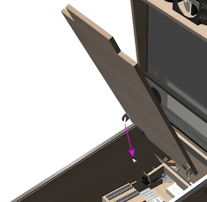
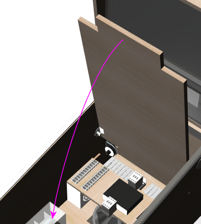
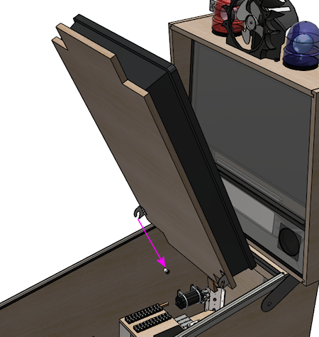
Step 13: Install and test. Hold the TV-and-platform assembly up so that
it's almost vertical. Position it over the pivots in the cabinet.
Lower the brackets onto the pivots. Once they're seated, lower the TV
onto the front stops. Test the tilt action, checking clearances at
the front and back.
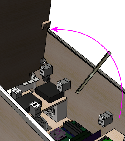
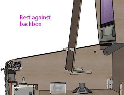
Step 14: Add something to hold the TV up. You'll need something
to hold the TV in the tilted-up position when you want to work inside
the cabinet.
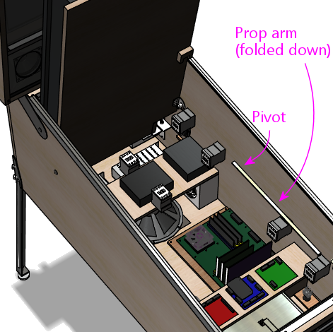
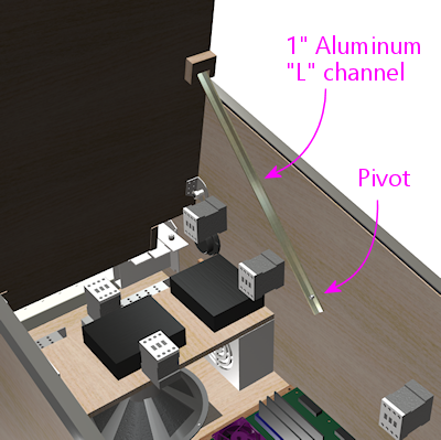
One option is to install a prop rod. The Williams System 11 and WPC
machines use this approach. On my own machine, I improvised one using
1" aluminum "L" channel, cut to a suitable length. It's attached to the
cabinet wall with a large bolt as the pivot.
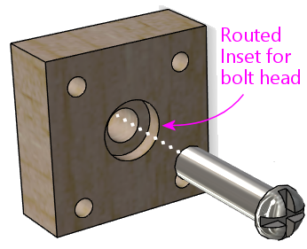
On the cabinet side, it's probably good enough to use a large wood
screw (perhaps #8) screwed into the cabinet wall as the pivot. This
does have to carry some weight, though, so I wanted something more
robust in my own cab. I used a bolt screwed into a separate wood
plate, with bolts on each side of the plate, and the plate screwed
into the cabinet wall with four wood screws.
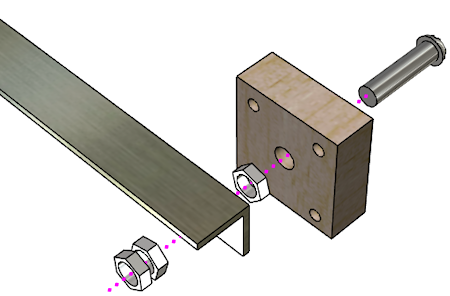
You could do the same thing more simply with a carriage bolt inserted
through the side of the cab wall, if you don't mind another external
bolt head adorning your artwork.
On the playfield side, I made a little wood bracket to keep it locked
in place when deployed:
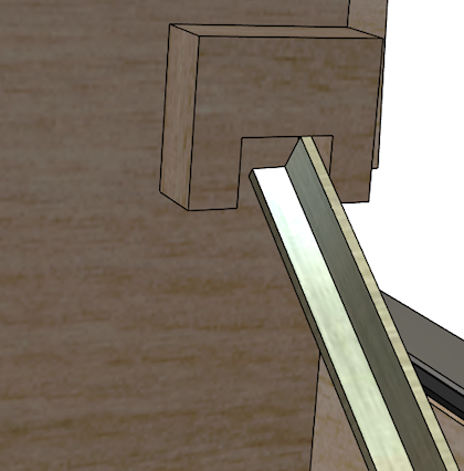
The prop-arm approach above has worked well on my machine, and it's
not too difficult to set up. If you want a simpler approach, you
could use a lanyard or luggage strap in combination with a couple of
eyelets - one on the playfield, one on the backbox. Simply attach
hook strap to the eyelets to hold the TV up.
Whatever solution you use, make sure it's sturdy enough. It won't
actually have to support a lot of weight most of the time, since most
of the weight will be on the pivots when the TV is tilted up. But you
should make it a little stronger than that, so it won't break or get
dislodged if you accidentally bump the TV while working.
Hanger brackets
There's one more engineering detail on the real machines that I want
to mention.
In the design above, the front end of the playfield rests on a couple
of "stops" on the sides of the cab wall, as described in "Install the
front stops" above.
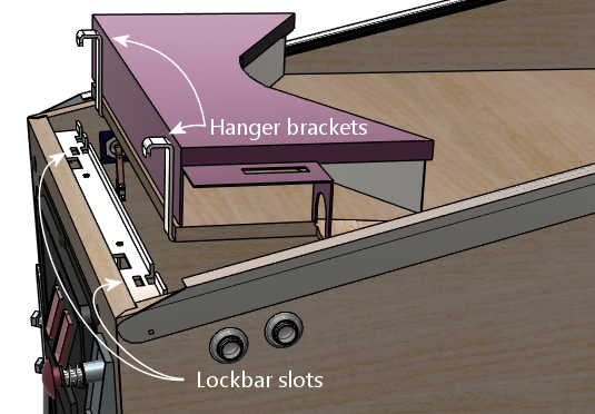
The real machines do something a little different. They use "hanger
brackets" to support the front of the playfield. These are metal
hooks at the very front of the playfield that fit into slots on the
lockbar:
In terms of the main job of holding up the playfield at the front, our
front stops work just as well. However, the hanger brackets serve
another function that our stops don't accomplish: the brackets also
serve to keep the playfield from tilting up whenever the
lockbar is in place.
Why is that important? Most of the time it's not, since gravity is
enough to hold the playfield down. However, there's one situation
where this changes: if you want to tip the machine up onto its back
for transport. When you do that, the playfield will want to tip away
from the lockbar. On the real machines, the hanger brackets will
prevent it from going anywhere, since the lockbar will hold them in
place. Our front stops won't do that. If you have a glass cover, the
glass will stop it - assuming it's strong enough to support the
weight. I'm not sure I'd want to count on that, especially if I
were putting the thing on a truck.
Given that we're using the standard pinball parts for the hinges, you
might wonder why we didn't also use the standard hanger brackets
instead of the improvised front stops. The problem is the fit. The
hanger brackets are only available in certain sizes that are designed
to fit real playfields. TVs are usually too deep for these to fit
directly. It would be possible to adapt them with some more complex
construction, but I thought the design was already complicated enough
as it is.
I don't have a good alternative solution hold-down solution,
unfortunately. I think the best bet if you want to ship the machine
anywhere would be to simply remove the TV and box it up separately.
It's some consolation that we've made it easy to remove the TV, at
least!
Apron mounting
Once you have the platform assembled, it's fairly easy to add an apron
equivalent, if you have unused space in front of the TV that you need
to fill.
My suggestion is to build a simple box out of thin plywood. The apron
doesn't have to carry any significant amount of weight, so this box
doesn't have to be especially strong. Attach it at the cutouts we
left at the front for the flipper buttons and plunger.
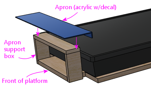
For the visible part of the apron, acrylic works nicely, since it has
such a nice flat, polished surface, and it makes a great base for
attaching a decal with custom graphics. You could also just use a
thin plywood sheet with a nice paint finish. Attach it with whatever
means are convenient, such as glue or foam tape, but I recommend
Velcro to allow easy removal and replacement should you ever want to
make changes.
For ideas about designing the apron's cosmetics, see "Apron" in
Finishing Touches. That section includes a template for
laser-cutting an acrylic cover with cutouts for standard-sized pinball
instruction cards.
On the real machines, the apron sits well above the playfield, usually
2 to 3 inches. You probably don't want quite that much depth on a
virtual cab; this is more about creating an impression than exact
duplication. I think a vertical distance of about 1" or a little less
looks good. On the other end, the apron should be set in a little
from the top glass as well, perhaps another 1" on that side.
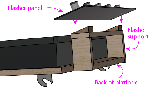
Flasher panel mounting
Adding a flasher panel at the back is basically the same as adding
an apron at the front. Build a little box to serve as the platform,
and mount the panel on top of that.
See Flashers and Strobes for more on designing and building the
flasher panel itself, including the electronics and how to
connect it to the software.
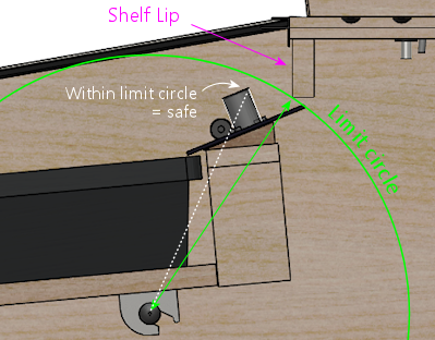
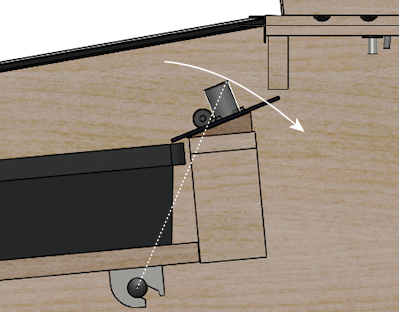
One extra detail that you have to pay attention to with the flasher
panel is clearance with the lip below the backbox shelf. Depending
on how your panel is set up, the domes might stick up above the
bottom of the lip. If they stick up too far, they might hit the
lip when you lift the TV.
The easiest way to be sure is to test it, but you can also figure it
out from the measurements when planning. The key is that everything
rotates around the pivot point, so everything always stays at exactly
the same distance from the pivot point - that is, everything moves
along a circle centered at the pivot. That means that the flasher
domes won't collide with the lip as long as the highest point on each
dome is within the limit circle of the shelf lip:
Alternative tilt-up design with a sliding pivot
The later WPC machines and modern Stern machines use a different, more
elaborate design that I at least want to mention, even though I don't
think it translates well to a virtual cab.
The newer machines use a sliding pivot point that lets the
playfield slide forward before tilting up. They switched to
this new system because it provides more vertical clearance than the
old fixed-hinge system, allowing for longer playfields and taller
ramps.
This approach might look attractive for a virtual cab, too, because it
solves some of the geometry problems that we discussed
earlier in "Determine the hinge
position". But on closer inspection, I don't think it actually works
that well for a virtual cab. The problem is that moving the pivot
point forward like this ends up blocking access to a larger portion of
the cab interior. That's fine on a real pinball machine, because the
cab interior is mostly empty anyway - most of the parts you want to
get to for service are on the underside of the playfield. But in a
virtual cab, we tend to install lots of stuff in the cab, so the
slide-and-pivot design works against us in that respect.
Given those geometry drawbacks, as well as the added complexity, I
don't think most virtual cab people will want to implement a design
like this. So I'm only going to offer an overview of how it works,
rather than going into such great detail as I did with the fixed hinge
system. I'd be happy to revisit the subject if there's enough
interest, though, so let me know what you think.
In the Williams WPC machines, they implement the pull-out system with
a rather complicated "slider bracket" mechanism, which uses
spring-loaded levers and latches to provide the sliding capability and
lock the pivot point in place at the forward and aft positions. The
slider brackets are mounted to the bottom of the playfield, taking the
place of the simple pivot brackets of the older design. As in the
older design, the slider brackets rest on top of pivot nuts mounted to
the side of the cabinet. The difference is that the slider brackets
let you move the playfield back and forth across the pivot point, so
that you can pull it out (as illustrated above) before tilting it up.
The slider bracket system works nicely in the real machines, and I
think it would be possible to adapt to a virtual cabinet, but the
parts are expensive - about $75 for a set of the slider brackets. If
you're interested in investigating further, the Williams part numbers
for the slider brackets are are A-17749.1-1 (left side) and
A-17749.1-2 (right side); those mate with the same pivot nuts
(02-4244 or 02-4329) and 3/8"-16 x 1-3/4" carriage bolts as
in the older design.
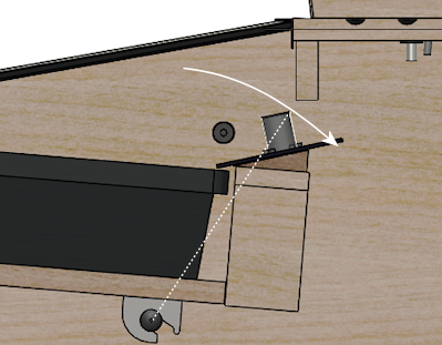
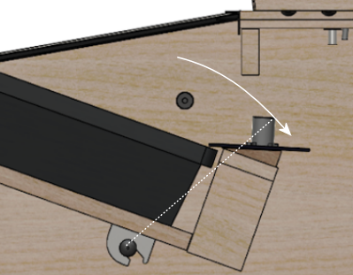
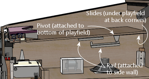
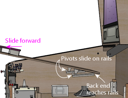
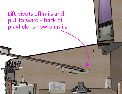
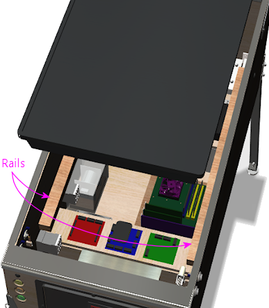
Stern's modern machines also have a pull-out system, but they use a
completely different mechanism. Stern's system is simpler and
cheaper, but some Stern owners say that it's a bit clunky to operate.
Stern's design essentially inverts the Williams design: it uses pivot
pins on the bottom of the playfield instead of on the side
walls, and has rails mounted on the side walls that the pivot pins
ride on. To slide the playfield forward, you slide it along the rails
until it reaches stops at the front. The clunky part is that the
Stern rails don't have the spring latches that lock things in place at
the different positions in the Williams design; instead, they rely on
gravity and little bumps in the rails. Here's an illustration of how
the mechanism works:
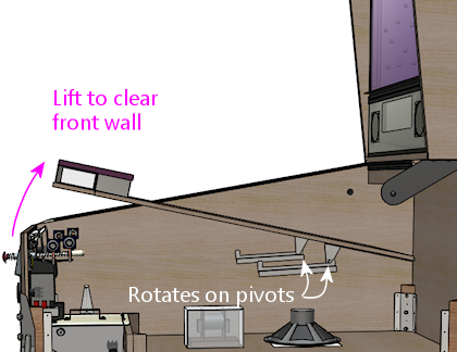
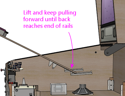
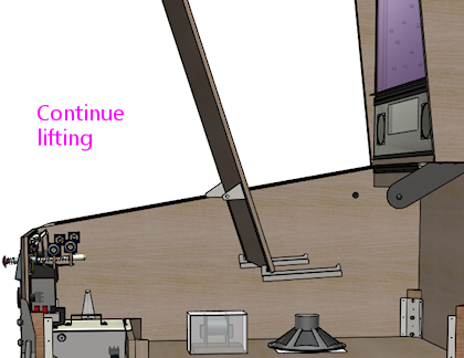
As you can see in the illustrations (which I've tried to keep to
scale), the bottom of the playfield ends up positioned much further
forward in this design than in the fixed-hinge system. That's really
the whole point, since that's how this system deals with the geometry
problems of the fixed-hinge system, but it's a negative for a virtual
cab because it only gives you access to the front half of the cab.
You're likely to have things mounted further back than this.
If you do want to go with this system, I think you could easily adapt
the step-by-step installation procedure outlined earlier for the fixed
hinge system. The parts in the two systems are analogous, so you
should be able to use the same techniques to measure and align
everything. Here are the Stern parts you'd need:
- Pivot brackets, 500-5329-03 (alternates: 500-5329-00, 500-5329-01, 500-5329-02) (quantity 2)
- Left side wall support rails, 535-5990-00
- Right side wall support rail, 535-5989-00
- Carriage bolts, #10-24 x 1-1/4", black (to attach the side support rails to the walls) (quantity 6)
- #10-24 hex nuts (quantity 6)
- #10 lock washers (quantity 6)
- Playfield slides (attach to the rear outside bottom edges of the playfield), 535-5988-01 (quantity 2)
Also see the
EZ slide playfield support brackets at Back Alley Creations.
That's an after-market replacement for the original Stern support
rails that's supposed to offer smoother operation. (The Stern parts
are all metal, without any wheels or bearings, so there's a lot of
metal-on-metal scraping involved. The "EZ slide" replacements use a
smooth plastic for the rails to make it less of a nails-on-chalkboard
experience.)
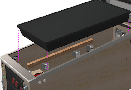
Rail mounting
A simpler alternative to the tilt-up mounting is to rest the playfield
on rail supports along the sides of the cabinet. This still lets you
access the cabinet interior when needed, by removing the TV, although
it's not as convenient as simply lifting the TV without removing it
as you can do with the tilt-up design.
While this is a little simpler to build than the tilt-up mounting, I
wouldn't use it myself. I consider it too inconvenient, since you'd
have to entirely remove the TV (and unplug all of its cables) every
time you wanted to get into the cabinet. That would turn minor work
into a big hassle.
Some random thoughts if you use this type of design:
- For the supports, I'd only use rails along the sides of the cabinet, not across the width of the cabinet. Cross-bars make it more difficult to reach into the cabinet.
- Be sure your TV is adequately supported underneath. Some TVs might not be strong enough to be suspended from the sides only. You might still want to mount the TV to a plywood base via its VESA anchors, as in the tilt-up mounting design above, then rest the plywood base on the rails rather than placing the TV directly on the rails.
- A base would also allow you to build the flasher panel and/or apron area into the TV assembly, as in the tilt-up design. This lets you remove the whole thing as a unit when you need to access the cabinet interior.
Routed slot mounting
If you want to use a TV that's slightly wider than the interior
width of your cabinet, you can route grooves in the side walls
that the TV fits into.
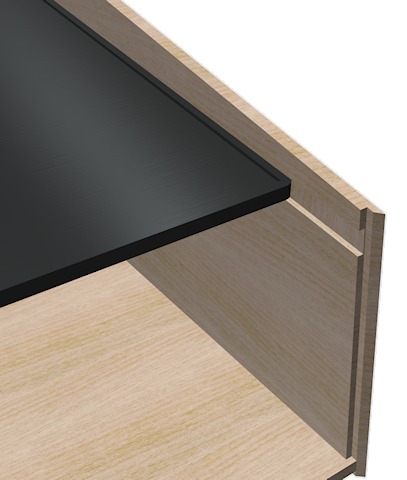
This is similar to the "rail" design above, in that the TV is
supported from the sides. As with the rail design, you should make sure
that your TV is strong enough to be suspended this way, and if not,
add some kind of base underneath to support it.
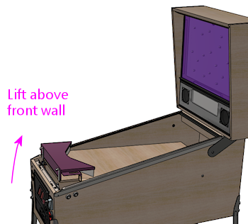
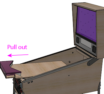
The main attraction of this approach is that it can produce a
"wall-to-wall" video screen effect, by hiding the TV's bezels in the
grooves. I can see the appeal, but it has too many functional
tradeoffs for me. In particular, with a routed slot mounting, you'd
only be able to get the TV in and out by sliding it through the front
wall. In other words, you'd have to remove the front wall to
get the TV out, and that's impossible with a conventional cabinet
design, since the front wall is permanently attached. To me, it's a
must that you be able to access the interior of the cabinet at any
time, so I wouldn't use this approach unless I could find a way to
make the TV easily removable without having to disassemble the whole
cabinet.
Permanent installation
Some people install their TVs permanently, fastening them directly to
the cabinet with screws, nails, or glue, with no provision for tilting
up the TV or otherwise moving or removing it. You can't beat the
simplicity of this approach, but I'd personally rule it out for any
cab project of my own, since it would make maintenance and repair so
difficult.
