102. Plunger Setup (Potentiometer)
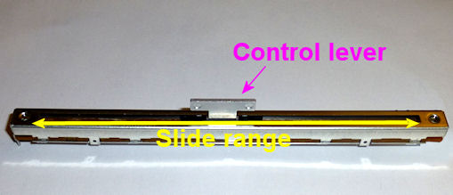
The easiest type of plunger sensor to build is a sliding
potentiometer. A potentiometer (often called a "pot" for short) is
basically a continuously variable resistor. The sliding type has a
control lever that slides back and forth in a straight line - just
like a plunger. By connecting the end of the plunger rod to the
potentiometer lever, we can make the lever slide back and forth in
sync with the plunger. This in turn makes the potentiometer's
electrical resistance change in sync with the plunger position, so by
measuring the resistance, we can determine the position. The KL25Z
helps us out with this by providing a built-in ADC (analog/digital
converter), which can precisely measure the analog voltage on a GPIO
pin.
This is one of the simplest possible position sensors, since all we
have to do is connect three wires between the pot and the KL25Z
(power, ground, and the variable resistance).
Here's how this works for sensing plunger position:
- Physically, you install the potentiometer in the cabinet adjacent to the plunger, fixed in place. You connect the control lever on the pot to the end of the plunger, so that the control lever moves in unison with the plunger.
- Electrically, the resistance on the pot varies according to the control lever position, so whenever you move the plunger, it changes the resistance on the pot accordingly.
- The software tracks the plunger position by monitoring the electrical resistance (actually the voltage, which is directly related to the resistance) and converting that to a position reading.
Potentiometers are inexpensive (about $6) and easy to install. They
work well, but they're analog devices, so they have a little random
noise in the signal that can be visible as a small amount of jitter in
the on-screen plunger position. The Pinscape software tries to
minimize that by taking many readings and averaging them together, and
has an adjustable "jitter" filter to calm any remaining noise in the
signal so that it doesn't show up as jumpy on-screen animation.
Oak Micros's pre-built kit
No longer available as of June 2021. Oak Micros formerly sold a
kit with all the parts needed for the plunger setup, including an
easy-to-install mounting bracket, but announced in June 2021 that
they're no longer selling their products. Here's the original
announcement on vpforums, if you want to check for any updates:
Selecting a potentiometer
The parts list section has a specific slide
potentiometer that's known to work well, but there are other similar
devices available. You can use any slide potentiometer that meets
these guidelines:
- 10 kΩ overall resistance
- Linear taper
- About 100mm travel length
Important: Pay special attention to the "linear taper" part.
It's not a reference to the physical arrangement with the
sliding control lever. It's an electrical spec that describes how the
pot's resistance varies across its range. There are two main types of
pots: "linear taper" and "audio taper". A linear taper means that if
you plot the resistance vs. the control arm position, you get a
straight line. With an audio taper, you get a logarithmic curve.
It's important to get a pot with a linear resistance taper, because it
gives you nice uniform distance readings across the whole sliding
range. If you get an audio taper type instead, the software won't be
able to convert the readings properly.
The absolute minimum length that will work is 85mm, but I'd look for
something in the 100mm range, because that gives you a little leeway
at each end to make sure the plunger doesn't bash the lever against
the potentiometer's limits.
If you're using the expansion boards, you'll also want to pick up the
connector specified in the parts list to make it easier to plug into
the boards. If you're using a standalone KL25Z (without the expansion
boards), see KL25Z Hardware Setup for recommendations on
connecting wires to the board.
Wiring
The wiring for a potentiometer is pretty simple, since there are
only three wires involved. The only tricky part is identifying
which terminal on the potentiometer is which, since the pins on
the device itself are often unlabeled.
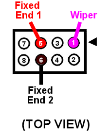
If you're using the recommended potentiometer from the
Electronic Parts List, the pins are arranged like this:

If you're using a different potentiometer, I can't tell you which pin
is which, since every device has its own pin arrangement. If the
device came with a diagram showing the pins, consult that, otherwise
check the vendor's Web site to see if they have a diagram.
If you can't find any information on your device, you can
figure out the pin arrangement by testing with a multimeter.
Follow this procedure:
- Set the meter to Ohms (Ω)
- Pick two pins to test
- Attach the leads from the multimeter to the two pins you selected
- Check the reading:
- If it reads 10 kΩ (or whatever your device's overall resistance is, if different), and it doesn't change as you slide the control arm back and forth, you've found the two fixed terminals
- If it reads something below 10 kΩ, and you see the reading changes as you slowly move the control arm back and forth, one of the pins you've selected is the wiper and the other is a fixed end
Test each pair of pins like this in turn until you hit upon the two
fixed terminals. Once you know which two are the fixed ends, you know
that the other one has to be the wiper by process of elimination.
Six-pin pots
If your potentiometer has six pins, you probably bought a type that
has two electrically separate potentiometers inside, both controlled
together by a single control arm. In this case, there will be more
combinations of pins to test, and there will be another type of
reading you'll see for some of the pairs: "Infinity" or "no
connection". These readings mean that the two pins you're testing are
on the two separate internal pots, so there's no connection between
them at all. Simply ignore these pairings, and continue testing other
pairs. Proceed until you find two fixed ends and a wiper that are
connected together and show readings as described above. Once you
find those, you'll only need to connect those three pins to the
Pinscape unit. You can leave the other three pins completely
unconnected.
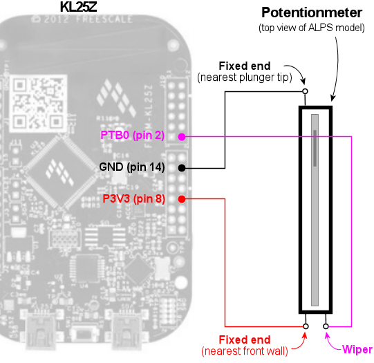
Standalone KL25Z wiring
Here's the schematic for wiring the stand-alone KL25Z,
without the expansion boards. The two "fixed" terminals on
the potentiometer are wired to 3.3V and Ground on the KL25Z,
respectively. The "wiper" or "variable" terminal on the
potentiometer is wired to an "analog in" port, such as PTB0.
I recommending using a plunger sensor
breakout board to connect to the standalone KL25Z. It'll make
things easier in the long run by giving you a pluggable connector
between the plunger and KL25Z.
- Follow the "Expansion board wiring" instructions below to build a pluggable connector for the potentiometer itself
- Follow the instructions in Plunger Sensor Breakout Board to build the breakout board
- Connect the following wires between the breakout board and the KL25Z:
- Breakout board B0 to KL25Z PTB0 (pin 2 on J10)
- Breakout board 3.3V to KL25Z P3V3 (pin 8 on J9)
- Breakout board GND to KL25Z GND (pin 12 or 14 on J9)
Expansion board wiring
For the expansion board connector, build a 4x2 crimp pin housing
(housing, pins).
First crimp a pin to the end of each wire (see Crimp Pins).
Insert the pins in the housing, following the diagram below for the pin placement.
Physical installation
I'd recommend getting all of the electrical wiring to the
potentiometer in place before installing the pot in the cab, since
it'll be hard to access the little contact pins on the pot after
installing it.
If you're using the ALPS potentiometer recommended in the parts
list, you can find 3D printer plans for a mounting apparatus
below, along with installation
instructions.
If you're using a different potentiometer, you'll have to either
modify our 3D printer plans to fit your device, or improvise
something of your own. It's pretty easy to come up with an
ad hoc mounting system using off-the-shelf hardware. Here
are the basic requirements:
- The body of the potentiometer needs to be fixed in place in the cabinet.
- The potentiometer's control knob must be firmly anchored to the plunger rod, so that moving the plunger moves the control knob by the same amount. The attachment should have as little play as possible.
- Don't worry about the orientation of the sensor at this stage. If you get it backwards, you can simply tell the software to reverse the readings.
3D printer plans for ALPS potentiometer mounting
If you're using the ALPS potentiometer from the
parts list, here's a set of 3D printing plans
you can use to mount it in your cabinet.
Other parts needed:
- Standard Williams/Bally plunger assembly
- M3 x 5mm to 8mm machine screws, quantity 2 (the exact length needed might vary depending on how the 3D-printed parts come out, so you might want to buy both lengths and use the one that fits best)
Fabricating the parts: The ZIP file contains five STL files.
Four of the STL files are the individual pieces that make up the
bracket assembly. The fifth file, Combined Parts.stl, contains
all of the other parts joined together into a single contiguous 3D
object, using the "model airplane" style where the piece are connected
by little plastic struts. The combined parts file lets you
manufacturer all of the parts in a single printer run.
You only need to print either the individual part files
or the single combined parts file. If you're using a
commercial 3D print service, I'd recommend using the combined parts
file, because many of the online services charge an extra fee for each
file you print, so it's cheaper to print the whole batch as a single
file. If you have your own 3D printer at home, use whichever
approach is more economical and easier for you.
3D printing guidelines:
- The STL files use millimeter (mm) units
- You can use any plastic material you wish, but I'd recommend Nylon PA-11 or PA-12 if you're using an online service, as those have excellent durability
- See Resources for links to online 3D print services if you don't have a 3D printer at home
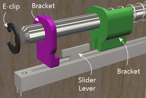
Note that my illustrations below show each part in a different color,
but that's only for the sake of clarity in the illustrations. There's
no need to use different colors for the actual printed parts.
Installation: If you printed the combined parts file, separate
it into the individual parts, by cutting the pieces apart at the
little struts holding them together.
If you've already installed the plunger assembly in your cabinet,
remove the top two screws. Leave the bottom screw installed.
If you haven't installed the plunger assembly yet, install it now,
fastening only the single bottom screw for now (leave the top
two screws out).
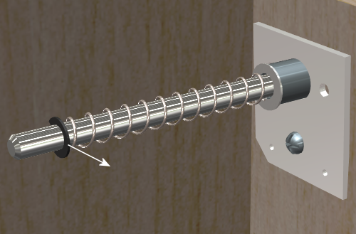
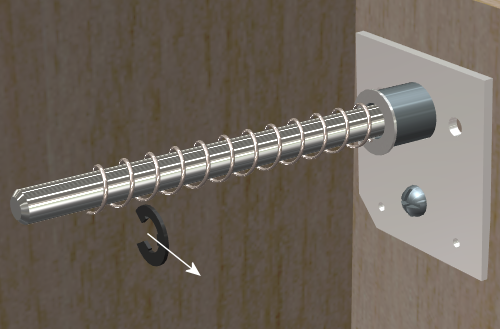
Remove the rubber tip from the end of the plunger if it's there, and
remove the e-clip. The e-clip is the little semicircular metal
fastener near the end of the plunger that holds the spring in place.
The e-clip simply snaps out by pulling it sideways. You'll need to
use needle-nose pliers to get a strong enough grip. It also helps to
hold back the spring while working so that it doesn't apply extra
pressure to the clip. You can leave the spring in place after
removing the e-clip.
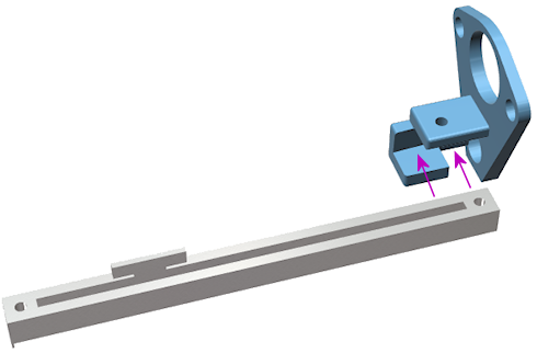
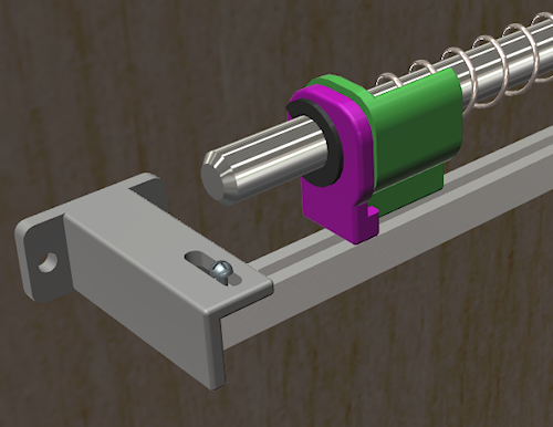
From the plastic set, find the "front bracket" piece illustrated
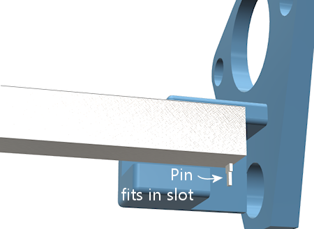
below. Slide the potentiometer into the slot as shown. Be careful
not to damage the electrical connector pin on the bottom of the pot -
the pin should fit into the slot at the front.
It doesn't matter which end of the pot you call the "front" at
this point. You can easily switch directions in the software
after installing it, so it doesn't matter if it's "backwards"
initially.
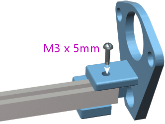
When the potentiometer is seated properly in the slot, the mounting
screw hole at the end of the potentiometer should align with the screw
hole in plastic piece. Install an M3 machine screw in the mounting
hole to fasten the pot and bracket together. (As mentioned earlier,
there can be some variation in how the 3D-printed parts fit, so the
ideal screw length needed can vary; something in the 5mm to 8mm range
should fit. Do a test fit with the different sizes and choose the
length that works best in your setup.)
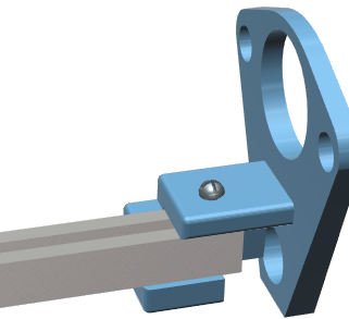
Leave the screw a little loose for now, since we'll want a little play
when we finalize the alignment with the other parts later.
Now slide the bracket-and-pot assembly onto the end of the plunger,
and all the way back until the bracket is sitting flush against the
plunger mounting plate.
Reinstall the two top mounting screws that we removed from the plunger
assembly at the start of the procedure. Fit them through the holes in
the front plastic bracket. Don't over-tighten, as that could crack the
plastic piece.
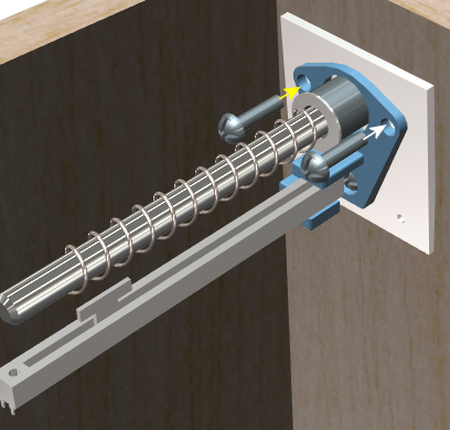
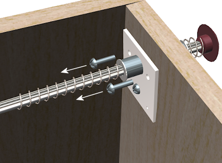
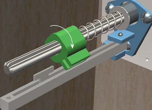
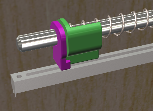
Now we're going to install the plastic bracket that connects the
plunger to the slider lever on the pot. This connector bracket is
actually two separate pieces. They work together to form a clamp that
grips the pot lever from the front and back. The brackets fit over
the plunger rod, between the spring and the E-clip. The tension of
the spring holds everything in place.
Install the larger bracket first, by slipping it onto the plunger
rod as shown below and maneuvering it behind the slider lever. You'll
have to compress the spring a bit as you put it in place.
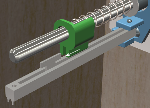
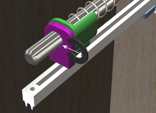
Slide the bracket over the potentiometer lever.
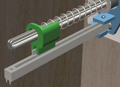
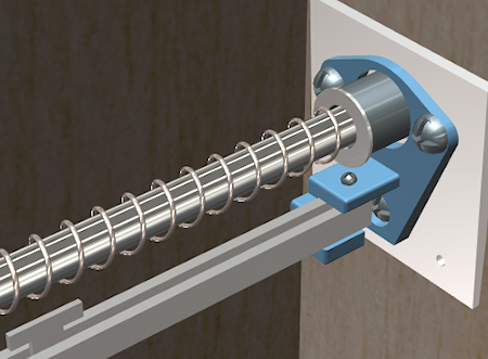
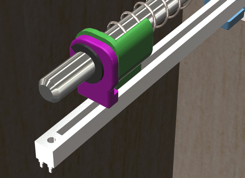
Slip the smaller bracket onto the plunger rod, and slide it back
until it meets the larger bracket. The two should clamp over the
pot slider lever. There'll be a little space between the two
brackets when you're done, because the slider lever on the pot
is a little wider than the spacing between the brackets. That's
intentional, so that the brackets clamp down on the slider to
make a solid grip with no play.
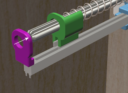
Push the brackets back against the spring far enough to make room
for the E-clip to fit into the matching slot on the plunger rod,
then re-install the E-clip. The E-clip just snaps into place with
a little sideways force. I find it easiest to do this with
needle-nose pliers.
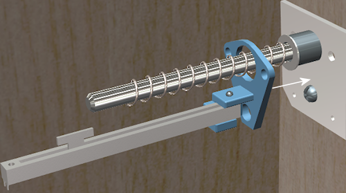
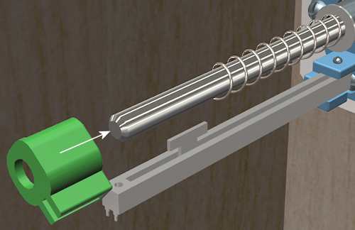
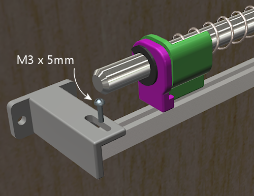
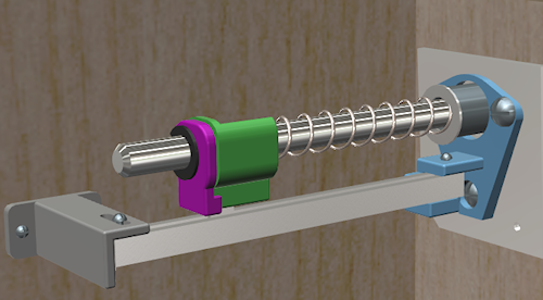
The last step is to install the bracket at the far end of the
potentiometer. This bracket attaches between the pot and the side
wall of the cabinet. Fasten the bracket to the potentiometer with an
M3 machine screw. Keep it loose for now so that we can fine-tune the
positioning before tightening. (As before, the screw length should be
from 5mm to 8mm long; choose the length that fits best with your
parts.)
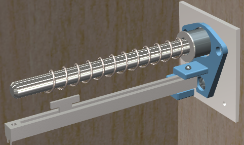
Before attaching the bracket to the wall, slide the plunger back and
forth a few times to get an idea of how it affects the vertical
positioning of the front of the pot. You'll want to pick a position
for the bracket that allows the pot to move freely across its whole
range, to avoid friction or stress on the mechanism. Once you've
found the right position, screw the bracket into the side wall with a
couple of #4 to #6 wood screws. (Sheet metal screws work equally
well.)
Lemming77's design (not for ALPS)
Here's another 3D-printer plan (in Sketchup format) for a mounting for
a different potentiometer, created by lemming77 on
vpforums. These plans are not the ALPS
device from our parts list - they're for some generic OEM part
found a long time ago on Aliexpress, which is probably no longer
available. You might be able to use these plans as a starting point,
but be aware that you'll have to modify them to fit your device's
dimensions.
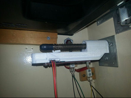
Lemming77's (vpforums) design for an older OEM potentiometer from Aliexpress,
printed from the Sketchup plans linked above.
Software setup
If you haven't already set up your KL25Z with the Pinscape firmware,
do that first. See KL25Z Software Setup.
Start the Pinscape Config Tool. Click the Settings button for your
device. Scroll down to the Plunger section. In the Sensor Type
drop list, select Potentiometer.
If you're using the expansion boards, the pins should be configured
automatically. If you're using the standalone KL25Z, set the
"Wiper" field to the GPIO pin that you connected to the "variable"
terminal on the potentiometer.
Save the new settings by clicking "Program KL25Z" at the bottom
of the window.
You should now test and calibrate the plunger. Return to the home
screen in the Config tool and click the Plunger icon for the unit
with the sensor attached. This will let you look at the raw
input from the potentiometer. When you move the plunger, the
green bar in the setup window should move along with it.
If the green bar is responding, click the Calibrate button in
the plunger viewer window. This will begin the calibration
process. Follow the on-screen instructions. The plunger
should be ready to use when the calibration process finishes.
If you're not seeing any response on the green bar, you might want to
go back to the Settings window and make sure that the settings are
right. Confirm that you've selected the Potentiometer sensor type,
and double-check that the GPIO port you selected is the one you
physically wired on the KL25Z. Also make sure that the pin isn't
marked with a warning icon ( ). If it is, click the icon to
see what's wrong. In most cases, the problem is that the same
pin is assigned to multiple functions. If so, go to the other
place where the pin is assigned, and clear that entry by
setting it to "Not Connected".
). If it is, click the icon to
see what's wrong. In most cases, the problem is that the same
pin is assigned to multiple functions. If so, go to the other
place where the pin is assigned, and clear that entry by
setting it to "Not Connected".
). If it is, click the icon to
see what's wrong. In most cases, the problem is that the same
pin is assigned to multiple functions. If so, go to the other
place where the pin is assigned, and clear that entry by
setting it to "Not Connected".
If the software setup looks okay, check the physical wiring.
Inspect each wire between the KL25Z and the potentiometer.
Make each wire is connected to the right pin at both ends
(on the KL25Z and the potentiometer). Check that the GPIO
you assigned in the software matches the physical pin on the
KL25Z you've wired.
Backwards operation
If the on-screen plunger moves backwards from the real plunger, you
can fix it in the software without reinstalling the sensor. Open the
Pinscape Config Tool. In the row for the controller, click the
Plunger icon. Check the box for "Reverse orientation". (If it's
already checked, un-check it.) This tells the software to reverse the
readings from the sensor, so that it acts like it was installed in the
opposite orientation.
