11. Power Switching
When you push the ON button your virtual cab, you want everything
to turn on automatically: all the TVs, the audio system, the feedback
devices, etc. Likewise, when you're done playing, you don't want to
run around shutting everything off separately; you just want to press
the OFF button and have the whole thing shut down.
There are some challenges to achieving this kind of power integration,
but they can all be overcome with a little planning and setup work.
This chapter covers what you need to know to achieve single-button
on/off control.
Soft power control through the computer
The key to whole-system power control is to let the computer control
the power. Modern PCs are designed for "soft power" control, which
means that the operating system software controls the power to the
motherboard. This is how Windows shuts off power when you select
"Shut Down" from the Start menu.
Using the soft power control on the PC motherboard itself is easy.
You just need to wire a pushbutton to the power control pins on
your motherboard. These pins are usually part of the "Front Panel"
or "F_PANEL" header. If you were going to install the motherboard
in a regular desktop case, the case would have a 10-pin connector
that you'd plug into this header on the motherboard.
The exact location of the front panel header varies by motherboard,
but it's usually easy to find. Look for a 10-pin connector near one
of the edges of the motherboard. It's usually labeled F_PANEL or
FRONT PANEL.
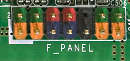
Intel defined a standard arrangement for this header a long time ago,
so almost all motherboards use the same setup. You should check your
motherboard's documentation to be sure, but the power switch pins are
almost always the red pins in the diagram above - pins number
6 and 8 in the standard numbering.
To power up the PC via the soft power control, all you have to do is
connect those two red pins together for a moment. To turn the power
off through Windows, just momentarily connect them again.
To connect a pushbutton to the soft power controls, you simply connect
one terminal of the pushbutton to one of the red pins, and the other
terminal to the other red pin. It doesn't matter which order they're
connected in.
The standard place on a virtual cab to mount the power button is
on the bottom of the cabinet, at the lower right corner. See
the "Floor" section in Cabinet Body for
the standard location in the WPC cabinet plans.
Type of connector use with F_PANEL
The standard F_PANEL connector uses two rows of pins with 0.1" pin
spacing. This is a standard type of connector. To learn more about
how to build a plug to connect here, see "0.1" pin headers" in
Connectors. I'd recommend building a connector using a
0.1" crimp pin housing, as described in that section.
Controlling everything else through the PC
If you have a desktop PC, you've probably noticed that your monitor
shuts itself off whenever you power down the computer, and turns
itself back on when you boot up the computer. You don't have to worry
about switching your monitor on and off separately; it just follows
the PC's lead.
That's the template for how the cab should work. We want the TVs and
everything else in the cab to follow the PC's lead when turning on or
off.
Unfortunately, we can't count on the other devices in a pin cab to
switch themselves on and off with the PC the way a computer monitor
does. Computer monitors only do this because they're specifically
designed for it. They work by way of the video signal. When there's
no incoming video signal, a monitor assumes that the computer is
turned off, so it goes into standby mode. Regular TVs usually don't
have this feature, nor do audio amplifiers or the miscellaneous power
supplies we use in a pin cab for feedback devices. So we have to give
them some help, by adding our own power control machinery that we
design to mirror the PC's power state.
There are two main options for implementing this, but they both work
the same way: they control power to the AC outlets for the TVs
and other devices, according to whether the PC is on or off.
The basic idea is that we install a power strip inside our pin cab,
with a set of outlets for plugging in the AC power cords for the
various devices. But we have two kinds of outlets in the power strip:
one special outlet for the PC, and a bunch of outlets for everything
else. The special outlet for the PC is always powered - that is, you
effectively leave the PC plugged into the wall outlet all the time.
The other outlets are switched, meaning that they only receive
power when the switch is on. When the switch is off, they don't
receive any power at all, so it's exactly like completely unplugging
whatever's plugged into them. We use those switched outlets for the
TVs, audio system, and all feedback devices.
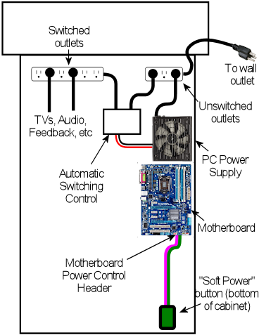
Conceptual outline of how the PC can control
power to other devices. The PC is plugged into an
outlet that always receives AC power, allowing it to be
switched on and off through the PC's "soft power" button. The
TVs, audio system, and feedback devices are plugged into a
second set of outlets that are controlled by an automatic
switching control. The automatic control cuts AC power to the
secondary outlets whenever the PC is off, forcing all of the
other devices to turn off.
The final piece of the puzzle is how the outlet switch is controlled.
It's not a "switch" in the sense of a wall switch that you operate
manually. Rather, it's an electronically controlled switch,
controlled by the PC's power state. When the PC is on, the switch
turns on automatically. When the PC is off, the switch turns off
automatically.
Since everything except the PC is plugged into switched outlets, all
of those devices have no choice but to follow the PC's lead. When the
PC is off, the switch cuts their power off at the source, so they have
to turn off immediately whether they want to or not. They don't need
any in-built circuitry to know whether the PC is on or off; we
override all of that and control their power at the source.
Let's look at the two main ways we can implement this "switched
outlet" setup.
Option 1: Smart power strip
You can buy pre-packaged "smart power strips" from Amazon or Best Buy
that implement the sort of behavior we've been describing. This is
supposed to be the easy way to implement a switched outlet, since it's
plug-and-play. Just plug your computer into the designated outlet and
the strip does its magic.
The reason I hedged by saying it's supposed to be the easy way
is that it doesn't always turn out to be that easy. Some people run
into snags with it, which we'll come to in a moment.
If you want to buy a smart power strip, try searching online stores
for "smart power strip" and "green power strip". ("Green" because
they save energy by cutting power to idle devices.) The specific
product I used in my cab is an APC P7GB, which works well for me.
A retail smart power strip will have a specially designated "master"
outlet or "computer" outlet, which is where you plug in the PC. The
smart switching feature works by monitoring this special outlet to see
if any power is flowing through it. When the sensor detects power
flowing through the master outlet, the strip figures that the PC is
on, so it turns on power to the other outlets. When the master outlet
isn't drawing any power, the strip assumes that the PC is off, so it
cuts power to the other outlets.
The good thing about this design is that doesn't require any special
cooperation with the PC. It doesn't need any special connections to
the PC or any special software. It works purely by monitoring the
PC's power usage through its main power plug.
The weakness of the design is that nearly all PCs draw a little bit of
power even when they're off, so the sensor in the smart strip that
detects power usage in the master outlet has to be calibrated to allow
for that. The smart strip can't just wait for the power level to drop
to absolute zero, because that never actually happens. To make
matters worse, there's no "standard" idle power level; every PC is a
little different, and it can even depend upon what's connected to the
computer, since some USB devices draw power through the PC even when
the PC is off. The maker of a smart strip doesn't know what kind of
PC you're going to use with it, so they can't tailor the threshold level
to your particular model. They just pick a level based on averages
across many models. This usually works, but not always. Some
PCs are so energy-efficient that they always stay below the threshold
levels, so a smart strip might never detect that those PCs are on.
Other PCs draw enough power when turned off that they remain above the
threshold levels at all times, so a strip might never detect that
those PCs are off.
Every strip has its own power threshold level, and every PC has its
own power characteristics, so it's not easy to predict if a given
strip will work with a given PC. The only way I know to find out is
to test the specific pairing. So if you're going to test a smart
strip, buy it from a store with a good return policy, in case it
doesn't work with your computer.
Another disadvantage of the packaged smart strips is that they usually
have a mix of switched and non-switched outlets, which means that they
don't have very many switched outlets. For example, my APC P7GB only
has three switched outlets out of 7 total, which isn't enough for all
of the things I need to plug into switched outlets. That's easily
solved by plugging a regular dumb power strip into one of the switched
outlets to create more switched outlets, but that takes up extra space
in the cab, so it would be tidier if the smart strip had more switched
outlets built-in.
Option 2: DIY switched outlets
Note: there's a retail product called the IoT Power Relay that's
almost exactly like the DIY solution we're about to describe, but it
comes pre-built, saving you the work of finding the component parts
and assembling them. You might also prefer it for safety reasons, if you're
uncomfortable working with high-voltage wiring. See
Option 3 below for more details.
A second way to implement automatic power switching is to build it
yourself. This is more complex than buying a retail smart power
strip, but it's more reliable and more flexible. It eliminates the
problem that some smart strips have with properly sensing the on/off
status of the computer. If you have any problems getting a smart
strip to work with your computer, you can use this approach instead.
This approach also makes it easier to add more switched outlets; the
smart strips usually only have three or four switched outlets, which
might not be enough for a decked-out pin cab. (With a smart strip,
you can always plug a dumb power strip into one of the switched
outlets add more switched outlets, but that takes up more space in the
cabinet. If you build your own DIY switcher, you can start with
a dumb strip that already has enough outlets for your needs.)
You'll need three things to build your own switched outlets:
- A small power strip (the ordinary "dumb" kind) with 2 or 3 outlets, to provide the unswitched outlets for the PC and the switched power strip
- A second ordinary power strip, with 6 or so outlets, to provide the switched outlets
- A 12VDC relay that can switch large power loads of at least 120VAC and 20A
For both power strips, I recommend buying strips equipped with
surge suppressors. The primary strip will be running your
PC, and the secondary strips will be running your TVs, so both
would benefit from surge suppression.
Relays that switch large loads are also known as contactors.
You can find suitable devices on eBay, built into little circuit
boards that simplify the wiring. Here's a picture of what to look
for:
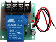
Search on eBay for "12V contactor board". You should be able to find
listings that look similar to the picture above. (You don't need to
find an exact match - the picture is just to give you an idea of what
they look like.) The most common type currently listed has output
limits of 250VAC and 30A, which is safely above our minimums.
Make sure the control signal is listed as exactly 12VDC.

Be sure that your relay or contactor has a diode installed
across the coil. This is important because it protects the
12V power supply and your PC electronics from the voltage
spikes caused by the relay's magnetic coil.
If you use an eBay contactor board, it'll
probably have such a diode pre-installed, but you should
visually inspect the board to make sure. If you're using
a plain relay or contactor you bought as a separate component,
you'll have to install a diode yourself. See Coil Diodes
for wiring instructions.
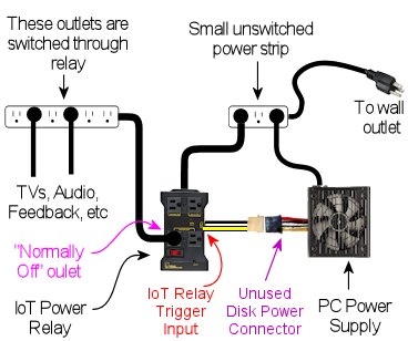
Here's the basic wiring diagram:
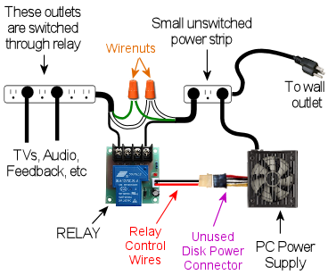
The theory of operation is simple. When the PC is ON, the PC power
supply sends power to the disk connectors. This provides 12V to
the relay, which turns the relay on, which in turn connects AC
power to the switched power strip. When the PC is in one of the "soft
off" modes, the PC power supply turns off power to the disk
connectors, which cuts the 12V power to the relay. This switches
the relay off, which cuts AC power to the switched power strip.
This is equivalent to unplugging everything connected to the switched
power strip, so all of the TVs and other devices will turn off.
Most of the connections shown are just a matter of plugging in power
cords: plug the PC power supply into the unswitched outlet, plug the
TVs and other devices into the switched outlet. But there are three
DIY steps required:
Step one: Find an unused disk connector on your PC
power supply. Connect the control wires from the relay
board to the disk connector wires as follows:
- Red relay wire → Yellow power supply wire
- Black relay wire → Black power supply wire
See How to connect 5V and
12V devices in the Power Supplies chapter for instrutcions on how
to connect wires to the disk connector plug.
Step two: Make absolutely sure everything is unplugged
for this step, because we have to cut into the AC power wiring.
On this step, we're going to cut the power cord in half for your
second power strip: the one with 6+ outlets that's going to
become the switched power strip. You don't have to cut it
exactly in half, though; you should cut it where it will be
most convenient for your physical layout. To figure out where that
is, you should take a moment to do a rough fit in your cabinet to
determine where you're going to situate the two power strips and the
relay. Look at the diagram above and observe how the power cord from
the second strip is going to be split into two parts, with the relay
in the middle. Find a good point to cut the power cord so that you'll
have a little slack on both sides of the cut when all of this is
assembled.
Inside the power cord, you're going to find three internal wires.
They should be color coded black, white, and green. The black wire
is the one that we're going to connect to the relay. This is the
"hot" or "line" wire that carries the voltage, so it's the one we
want to interrupt to switch the outlets off.
The white and green wires are going to simply connect directly across
both halves of the split power cord. In the diagram, we showed them
connected by wire nuts, because we're assuming that you're going to
have to cut the cord in half all the way through, severing all three
wires inside. If you're really careful, you might be able to save
that step by cutting only the black wire in half and leaving the white
and green wires intact. If you can manage that, there's no need for
the wire nuts. If you do end up having to cut the cord fully in half,
though, reconnect the white and green wires by stripping a bit of
insulation off the ends (about 1/2" worth), feeding the ends into a
wire nut, and twisting them together until their securely in place.
Make sure there's no exposed bare wire sticking out of the nut when
you're done. As shown in the diagram, connect green to green and
white to white - all we're doing here is undoing the cut and restoring
the green and white wires to their original condition. You might want
to wrap the nuts and some of the surrounding wire in electrician's
tape when you're done to secure everything in place.
The black wires connect to the input and output terminals on the
relay. It doesn't matter which black wire goes to the input and which
goes to the output; either way is equivalent. The relay terminals
might be labeled input and output or K0 and
K1. Many of these boards have four terminals; when they do,
each pair of terminals is simply connected together. For example,
there might be two terminals labeled K0; these are wired together
inside the board, so you can just pick one of the two to connect one
black wire.
Step three: Secure everything in place and cover the
high-voltage wiring for safety.
Once everything is wired, permanently fasten the relay board to the
cabinet floor (or wall) with screws. I'd also recommend using
standoffs, to leave a little open air under the board. Secure the
power strips in place. I'd also secure the cut power cord portions,
perhaps with wiring staples, to ensure that the wire nut joints aren't
jostled or stressed and that the black wires can't be accidentally
pulled out of the relay terminals.
Finally, you'll have to improvise a cover for the entire relay
assembly, so that there's absolutely no exposed metal or wire. The
black wires will carry AC line voltage, which is hazardous high
voltage. You don't want to allow anything loose in the cabinet to
come into contact with the AC wiring, and you don't want any risk of
touching it yourself while working in the cabinet. Remember that
the AC line voltage will be live on these wires whenever the
cabinet is plugged in, even when the computer is turned off. I'd
recommend going to Home Depot and getting a plastic electrical
junction box, of the type used inside the wall in your house wiring
for switches and outlets. Get a box big enough that the relay board
will entirely fit into it. Place it over the relay board and screw it
into the cabinet so that the relay is permanently covered.
Option 3: IoT Power Relay
There's a retail product, called the IoT Power Relay, that implements
the functionality described in the DIY
option above, but without the need for you to buy individual
components and assemble them. You can buy these from Amazon and other
online retailers; search for IoT Power Relay. As of this
writing (February 2021) they sell for about $27.
The IoT Power Relay is set up to trigger based on just about any AC or
DC voltage, so you can set it up exactly as described above for the
DIY option, using the 12V wires (yellow and black) from one of your
primary PC power supply's unused disk connectors as the trigger
source. Note that the IoT Relay's trigger input is polarized, so you
have to connect yellow and black in the correct order. Be sure that
the yellow wire from the disk plug connects to the "+" terminal of the
IoT Relay trigger input, and the black wire from the disk plug
connects to the "-" terminal of the relay trigger input.
Once you have that wired up, just get an ordinary "dumb" power strip,
and plug it into one of the IoT Relay's "Normally Off" outlets. The
Relay may have outlets marked "Normally Off", "Normally On", and/or
"Unswitched", depending on which revision you get. For our purposes,
you can ignore everything except the "Normally Off" outlets. Those
are the ones that switch ON when the trigger voltage from the main
power supply switches on. Note that you don't even need an extra dumb
power strip if you only need two switched outlets, since all
versions of the IoT Relay have at least two switched outlets built in.
For most cabs, though, that's probably not enough - you'll probably
have four or five things that you want to plug into the switched power
strip (secondary ATX power supply, 24V power supply, DMD or DMD video
panel, backglass TV, audio amplifier). The extra power strip is
just there to provide those additional outlets.
The TV Power Memory Problem
Now we come to the eternal bane of pin cab builders everywhere:
power memory, or more typically, power forgetfulness.
If you've been following along for the first part of this chapter,
your cabinet is now set up (or you at least have a plan) so that
everything in it will turn on and off automatically with the computer.
This happens thanks to our "smart strip", which controls AC power to
every outlet (apart from the computer's own outlet) according to
computer's power status.
The "power memory problem" in a nutshell is that many TVs won't
turn on with this setup. Instead, they'll go into "standby" mode,
where they'll stay dark while awaiting an IR remote control command.
A TV in standby mode won't show a picture even if it's receiving an
active video signal. This is bad for our "smart strip" system,
because the smart strip makes the TV think it's being plugged
in anew each time the PC is powered up. If the TV is designed to go
into standby mode each time it's plugged in, the TV will effectively
remain off, defeating our wonderful one-button power control.
How to tell if your TV has the problem
The only reliable way to determine if a particular TV has the power
memory problem is to test it. If you're still shopping and want to
test a TV before you buy it, you really have to find the exact model
you're considering in a showroom or friend's house and test that
specific TV. Don't count on similar models from the same manufacturer
working the same way; it's not consistent across product lines.
The thing that really makes it hard to shop for this feature is that
it's almost impossible to find good information about this online.
You won't find it listed in a spec sheet or Amazon product page, and
most people won't even know what you're talking about it if you ask.
Your best bet is to ask on the virtual pin cab forums, because at
least some people there will understand the question; even so, there
are so many TV models that it's always hard to find someone who owns
the exact one you're considering.
If you do have a way to test a model in person (or by proxy), you can
get a definitive answer using the following text procedure. Ideally,
you should try this using the same video input on the TV that you're
going to use when it's installed in your cabinet. For example, if
you're going to connect it to your PC by HDMI, run the test with the
TV set to view an HDMI video source. The reason this is important is
that some TVs have different behavior on this test with different
sources.
Here's the test:
- Plug in the TV
- Turn it on
- Let it run for a couple of minutes
- Unplug the TV without turning it off first
- Wait a few minutes
- Plug it back in
On that last step, if it turns back on and returns to showing the same
video source as before, hooray! The TV has good power state memory.
It should just work automatically with a smart strip in a pin cab, so
you shouldn't need to pursue any of the solutions below.
If the TV goes into standby mode after being plugged back in, it has
the problem. You'll need one of the solutions below if you want to
use it in your cab and you want single-button power control to work
properly.
Solutions to the TV power-on problem
Fortunately, the power memory problem can be solved. Here are several
possible solutions, in order of DIY-ness.
Solution 1: Buy a TV that doesn't have the problem
The easiest solution to this problem is to not have it in the first
place. You can simply decide when buying a TV that power memory is a
must-have feature, and reject any models that lack it.
My guess is that about 50% of the people in the pin cab forums would
agree with that approach, because they really don't want to mess with
any of the workarounds. Personally, I don't like this
approach, because power memory is hardly the most important thing to
me about choosing a TV. I think it's much more important to consider
picture quality, motion blur, input latency, physical fit for the
cabinet, price, and probably a few other features, before worrying
about whether it has power memory. You might rule out some otherwise
superior candidates if you consider this a deal-breaker. I'd only
consider power memory a "nice-to-have" feature, meaning I'd only use
it to decide between sets that are otherwise equals. The power memory
problem is solvable by the other means we'll see below, so it's really
not the end of the world if your TV needs a little help powering on.
Solution 2: Keep the remote handy
Of the 50% of cab builders who don't think power memory is the
king of all TV features, I'd guess that about 50% of them throw in the
towel on single-button power-up if their TVs don't have it. Because
there's always the easy manual solution: keep the remote handy and
press the On button every time you power up the cabinet.
This really isn't a terrible solution. I'm too much of a
perfectionist to accept it for my own cab. It's not the inconvenience
of it that's the problem for me; it's just that it makes the project
feel a little unfinished. But in practical terms, it costs no
significant amount of time and is only a minor inconvenience. If you
can live with the rough edge, and the solutions below seem like more
trouble than they're worth, you can stop here and call it done.
Solution 3: Tape down the On button
For some TVs, you can get away with a simple hack. It's
inelegant (which is, after all, the proper definition of "hack"), and
it doesn't work at all on most TVs. But it's worth trying, because if
it does happen to work on your TV, it's a really simple solution
that you can implement in a matter of minutes.
Here's the idea. On some TVs, if you keep the on/off button pressed
down all the time, the TV will turn on and stay on whenever you
plug it in. If your TV works this way, you can improvise some simple
mechanical way of keeping the button pressed down permanently.
Before you start thinking about how to stick the button down, test
your TV to see if the trick works for it:
- Unplug the TV.
- Manually hold down the On/Off button.
- Keep holding down the button while you plug in the TV.
- Keep holding it down continuously for a couple of minutes.
Don't let go even briefly on that last step. The point is to test to
see if holding the power button down for 10 seconds or 30 seconds or
60 seconds activates some special hidden action, like powering the TV
back off, or rebooting it, or bringing up a service menu. "Long
press" gestures often do something special like that on modern
electronics, since everything these days needs to have a way to reboot
it in case of software crashes. 30 seconds is almost always enough
for a "long press" to take effect, but I'd give it a couple of minutes
just to be sure.
If the TV turned on and stayed on, and you didn't activate some
special hidden action by holding down the button for a long time, the
hack will work.
To implement the hack, you just need to fashion something mechanical
to hold down the button permanently. For some models, it's as easy as
wrapping some duct tape around the bezel to apply pressure to the
button. If that doesn't work for your TV's geometry, try taping a
small object (a few pennies, perhaps) between the button and the tape,
or try fashioning the right shape out of a paper clip or a little
strip of sheet metal. If you have a 3D printer, maybe you can come up
with the right shape for a custom plastic clip.
The big limitation of this hack is that it only works for certain TVs.
Many TVs will respond by cycling repeatedly between On and Off or
activating some special action. That's why you should try the test
before worrying about how to implement the hack.
Solution 4: Pinscape TV ON system
If you're using the Pinscape expansion boards, there's a feature built
in to help deal with TVs that won't turn on automatically when plugged
in. The Pinscape boards have a power sensor that tracks the power
supply status, and two mechanisms for sending an ON command to the TV:
a relay that can be hard-wired to the TV's On/Off button, and an IR
emitter that can be programmed to send the TV's IR remote control
command code to turn on. These features can be configured in the
Pinscape software to send the TV ON signal (by relay and/or remote)
after an adjustable delay interval after the rest of the system powers
up, to give the TV a chance to "boot up" and make itself ready to
receive commands.
See TV ON Switch for full details.
Solution 5: eBay timer board
You can build your own equivalent of the Pinscape TV ON feature using
a type of electronic timer circuit board available on eBay.
Note: I recommend against using this solution, because it
requires taking the TV apart; it's only included here for reference.
If possible, use the Pinscape IR transmitter solution instead.
See TV ON Switch. The IR approach is non-invasive and fairly
easy to build. You can use it even if you're not using Pinscape for
anything else.
This approach works by simulating a manual button press on the TV's
On/Off button, shortly after the system power is turned on. We don't
physically press the button, but rather simulate it electronically, by
soldering wires to the button's switch contacts and connecting them
briefly at the proper moment.
There are three important details required to make this work properly:
- We have to sense when the TV power switches from OFF to ON
- We have to wait a few seconds after that, to give the TV time to initialize
- We have to simulate a momentary button press only; we can't continuously hold down the button.
To accomplish all of this, we need a timer circuit. The circuit has
to be triggered by the power coming on. It then has to pause for a
delay time, long enough for the TV to get ready to accept command
input, then it has "press the button" for just a moment. Here's
what the timing looks like:
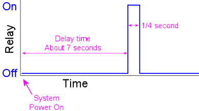
We're assuming that the timer is controlling a relay (an electronic
switch). The "button press" is simulated by the relay toggling on
briefly.
To implement this, we need the timer circuit itself, and then we need
to connect it electrically to the TV's On/Off button.
Buying a timer: Suitable boards are available on eBay, but
unfortunately it's rather difficult to find the needle in the haystack
for this sort of item. The ones you're looking for are no-brand
hobbyist products sold by Chinese companies, so there's not a
particular store or product name I can point you to. You'll have to
sift through the listings to find the right thing, but here's an eBay
search term you can use as a starting point: "relay cycle timer".
To find the right timer, first make sure you find something with a
relay. Most of the timer boards you'll find do use a relay, but some
use solid-state switches (such as MOSFETs) instead. A relay is
important for this application. Second, read through the descriptions
and look for a list of "modes". The mode you're looking for should be
described like this: "when the power turns on, the relay is
disconnected, then delay T1, turn on the relay, delay T2, turn off the
relay".
When you get the board, you'll have to program it according to the
instructions (if any are provided) to set the correct mode and delay
times. Set the initial delay time to about 7 seconds, and the second
delay time to about 0.25 seconds. You can test that it's configured
properly by cycling the power: each time you plug it into power, there
should be about a 7 second delay, and the relay should click ON and
immediately OFF.
Connecting to the TV: You'll have to be comfortable with taking
the TV apart at this stage, because we have to connect some wires to
the On/Off button.
There are no generic instructions for taking a TV case apart, so you're
on your own for this part. Your goal is to open the case and expose the
little circuit board containing the On/Off button.

Needless to say, use extreme caution with this step. In modern LCD
TVs, the LCD panel and polarizing filter are very thin, brittle
plastic sheets and often have no structural support other than the
outer case, so it's very easy to crack them during the removal process
or after the case is off. Removing the case will also void the
warranty, so you're assuming the entire risk of breaking something
by proceeding.
Once you get the case open, you should find a little circuit board
located under the area where the buttons on the case are situated.
It's usually long and narrow, and looks something like this:
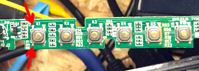
The red arrows in the photo above show the soldering points for the
button leads. The little squarish silver objects are the buttons.
These are normally situated immediately under the exterior plastic
buttons on the TV's bezel; pressing on the exterior plastic button has
the effect of pushing down on this metal part, which is the real
button.
Once you find this circuit board, identify which button corresponds to
the On/Off button on the outer case. Do this by position: just find
the inner button that's situated underneath the On/Off button on the
case. You can also do this by counting buttons from right to left,
since there should be the same number of silver buttons on the circuit
board as plastic buttons on the case.
Next, identify the switch leads. There are probably four leads to
these switches, one at each corner. On the TVs I've looked at, the
leads are in pairs that are electrically connected together, so there
are really only two wires here even though it looks like four. Put
your multimeter in continuity test mode and check the leads in pairs.
Find a pair that are not connected normally, but that become
connected when you press the button. These are the leads you want
to solder to.
The next step is possibly even more delicate and tricky than opening
the case. You have to solder wires to the button leads you just
identified. To do this, use fine hookup wire, 24 AWG or thinner.
Strip a very short length of insulation from the ends, around 1/8".
Melt a little solder onto the end of the wire. Position the end of
the wire at the desired contact point. Now get out some tape (I used
thin strips of masking tape here) and secure the wire to the board a
couple of inches away from the contact point. The idea is to hold it
in place at the desired position before soldering so that the solder
can just flow over the junction with everything already positioned
properly. Once everything is in place, heat the end of the wire for a
few moments, long enough for the solder to melt and flow onto the
switch lead. Remove the soldering iron carefully and try to hold
everything very still for a few moments so that the solder can
solidify over the junction point. If all went well, the wire should
stick to the switch lead. The connection will be delicate at best, so
you'll want to secure the wire with a couple more pieces of tape to
minimize mechanical stress on it.
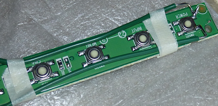
TV On/Off switch with wires soldered to leads
Repeat this process for the second lead. Once both are soldered and
held securely in place with tape, test your work with the multimeter.
Use continuity test again. Connect the meter leads to the free ends
of the wires you just soldered. The meter should read open/no
connection. Press the button, and the meter should read
closed/connected. If that works, you're set. Put the TV case
back together, taking care to run your newly attached wires out
a suitable opening.
Now you just need to connect the newly attached wires to the timer
board relay. Attach the wires to the relay common (COM) and
normally open (NO) terminals on the timer board. (If the relay
only has two switch terminals, those are the two to use!)
Finally, to power the relay board itself, connect its DC+ and DC-
terminals to the appropriate voltage inputs from the secondary
ATX power supply. For example, if it requires 5V for power, connect
its DC+ input to the red +5V wire on the secondary power supply, and
connect its DC- input to the black 0V/Ground wire on the secondary
power supply. See Power Supplies for Feedback for advice on connecting
wires to the power supply.
Note that you must use a secondary ATX power supply to power
the timer board (not the main PC power supply), and the
secondary power supply must be plugged into the switched power
strip. That's key to the whole scheme, because the timer board has to
be powered up at the same time as the TV in order for the countdown to
start at the same time the TV receives power.
Solution 6: DIY timer circuit
This works much like the eBay timer board described above, except that
it saves you the trouble of tracking down the right item on eBay. The
tradeoff is that you have to assemble your own circuit board instead.
But you don't have to design the circuit: you can just build it from
my plans.
As with the eBay timer board, I recommend against using this solution,
because it requires taking the TV apart. If possible, use the Pinscape
IR transmitter solution instead. See TV ON Switch.
You can download the schematic, in EAGLE and PDF format, along with
and an EAGLE printed circuit board layout, here:
Beta test warning: I haven't built or tested this incarnation
of the schematic linked above, which is an EAGLE rendition of the
original hand-drawn schematic I used to build the TV ON timer in my
own cab. The circuit I built based on the hand-drawn original is
well-tested (I've used it for several years without a hitch), but I
could have made errors doing the EAGLE translation. I also haven't
done a test run of the board design, although my experience has been
that EAGLE PCB layouts work fine as long as the schematic is sound.
If you're willing to be a beta-tester for these plans, please let
me know how it goes!
Before ordering parts, check your TV's timing! If you need
different timing, you will need to order different values for parts C8
and/or R10. These parts determine the initial delay time. The
delay time can be calculated from these as:
1.1 × R × C
where R is in Ohms and C is in Farads. With the default values
as shown in the shematic, the delay is 1.1 × 2.2M × 2.2uF
= 5.3 seconds. Before you order parts, test your TV to determine
if it requires a longer delay time:
- Unplug it
- Wait a few minutes
- Plug it in
- Use a timer to wait for 4 seconds
- Press the On button
If the TV turns on, try the test a few more times to make sure the
timing is reliable. If so, the default 5 second delay should work.
If your TV ignores the first button press on some trials, it probably
needs a longer delay time. Try the test again with longer wait times
until you find the shortest reliable waiting period. I'd add a second
or two to the result as a cushion. Now you can reverse the timing
formula above to find new values R10 and/or C8. For example, if you
need a delay of 7 seconds, you could keep the resistance value the
same and calculate a capacitor value of 2.89uF. Round up to the next
common size, which in this case is 3.3uF, which would make the actual
wait time about 8 seconds.
Build the board: Assemble the circuit, following the schematic
or using the printed circuit board (PCB) design provided in the plans.
The circuit is complex enough that I'd recommend building it on the
PCB rather than ad hoc. You can have the PCB manufactured by
OSH Park for about $12 for three
copies of the board, or at any PCB maker of your choice. You'll have
two copies of the board left over to give to friends or use on your
next cab!
Install the TV wires: The next step is to open your TV and
solder wires to its On/Off button. The procedure is described in the
section on eBay timers above.
Connect the board: Once you have wires connected to the TV's
On/Off button, connect the other ends of the wires to one of the "K1"
relay switches, on the Normally Open side. If you're connecting
directly to the relay, connect to pins 4 and 8 or pins 9 and
13. The relay in the spec is double-pole, meaning that it can
switch two separate televisions on at the same time. That's why you
have your choice of which relay pins to connect. If you have a second
TV that needs the same treatment, you can simply connect it to the
other pair of pins. If you use the PCB design, connect the TV wires
to JP12 pins 1 and 2 (labeled "TV1" on the board silkscreen) or
pins 3 and 4 ("TV2").
Connect power to the board: Finally, connect the power inputs
to your secondary ATX power supply. As with the eBay timer,
the scheme is predicated on the timer getting its power through a
source that's switched on at the same time as the TV, because the
power-on time is the start of the delay timer countdown. If you're
building from the schematic, connect VCC to +5V (a red wire) from the
ATX supply, and connect GND to ATX ground (a black wire). If you're
using the PCB layout, connect an ATX red wire to the JP7 +5V (marked
on the silkscreen), and connect a black wire to JP7 GND. See
Power Supplies for Feedback for advice on connecting wires to an ATX
power supply.
This circuit design is designed for this single function, so there's
no need to "program" it as with the eBay timers. All you have to
do is plug it in and it should work.
Solution 7: Use a USB IR transmitter
I'm only going to provide an outline for this solution, because I
haven't tried implementing it myself. You'll have to do a little
product research to fill in the details.
You can buy a device for your PC that lets you plug an IR transmitter
into a USB port. Software on the PC can then command the IR
transmitter to send a signal. You can use one of these to send the ON
command to your TV via IR remote during the Windows boot process.
I don't have any specific product recommendations, but your best bet
might be to search for "winlirc transmitter" or "winlirc blaster".
winlirc is open-source software that lets Windows send and receive IR
commands, so a winlirc-compatible device with a transmitter should
serve the function we need here.
Once you find a suitable device, install it on your PC and arrange the
IR emitter so that it's within range of your TV's remote receiver.
Now you just need to set up a script on the PC that sends your TV's
ON command while Windows is booting. You should be able to do this
by creating a .CMD file containing the command line sequence to
send the IR command, then placing a shortcut to the .CMD file in
your Start menu's Startup folder.
