48. Pinscape Outputs Setup (Expansion Boards)
If you've built a set of expansion boards, you're past the hard part.
Connecting output devices is fairly easy.
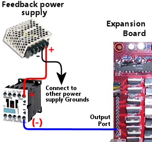
The Pinscape boards use the same basic wiring plan as other solid
state controllers, as described in
Feedback Device Wiring:
- Connect a wire from the positive terminal of the power
supply to the feedback device's positive terminal
- Connect the feedback device's negative terminal to an output
port pin on the Pinscape expansion board
- As described in Power Supplies for Feedback, you should already
have connected the power supply's negative terminal to the
common ground interconnect for all of the feedback power supplies
Repeat this pattern for each device.
For devices that run on the same voltage, you can either run a wire
from each device's (+) terminal all the way back to the power supply,
or you can daisy-chain the positive terminals together. You can do
whatever's most convenient for each device, and you can freely mix and
match.
It's fine to mix devices that run on different voltages, and it's
fine to connect them side by side on the same expansion board. Just
connect each device to its appropriate (+) voltage supply.
Config tool settings
Make sure you've configured the Pinscape firmware for your
expansion boards:
- Launch the Pinscape Config Tool
- Click the Settings icon for your device
- Near the top of the page, make sure that the System Type is set
to Pinscape Expansion Boards
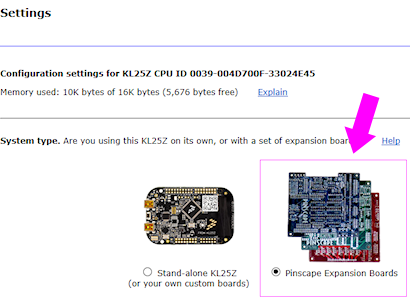
- Make sure that the number of power boards and chime boards is
set to match your physical configuration
Mixing power supply voltages
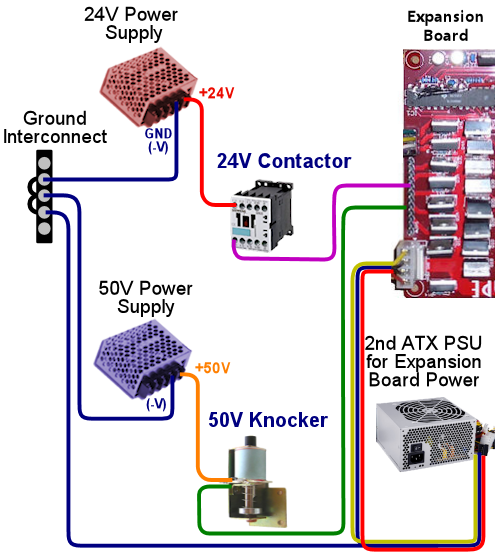
The Pinscape boards switch power on the "Ground" (negative or 0V)
side of the connection. This means that it's okay to mix different
devices with different power supply voltages.
This is confusing to a lot of people because they only see power
inputs on the Pinscape boards for 5V and 12V. But what if you want to
connect a 24V device? Or a 50V device?
Here's how you have to think about this. The 5V and 12V power supply
connections to the Pinscape boards are there to power the Pinscape
boards themselves. Those connections aren't there to power
the feedback devices. The feedback devices take their power
directly from the power supplies, not from the Pinscape
boards.
That means you don't have to connect the "+" from a 24V supply
anywhere to the Pinscape boards, but you can still connect it
to feedback devices that need 24V.
Use protective diodes if necessary
Most mechanical devices require protective diodes. These
are required for anything with a coil: solenoids, contactors,
replay knockers, motors.
See
Coil Diodes for details on what type of diodes to use
and how to install them.
Diodes are critical! Coils and motors can damage your PC motherboard
and other components if diodes aren't used.
Fuses
Many cab builders include a fuse in each device output circuit. This
isn't strictly necessary, but I think it's a good idea for the
higher-powered mechanical devices. Fuses can help protect the
Pinscape board from overloads caused by wiring faults and device malfunctions,
reducing the chance that the board will be damaged if something like
that goes wrong. See
Fuses for details.
Where to connect what
The expansion boards have a number of output ports that are designed
for particular device types. It's best to attach devices to their
special ports when present, since that takes the best advantage
of the special design features on the boards.
Here's a quick summary of where to attach each common device type. If
you're not familiar with any of these, we'll look at each type in
depth over the next few chapters.
| Device | Where to connect |
|---|
| Beacon (rotating police light) | Power board |
| Bell (one-shot type) | Chime board |
| Bell (reciprocating type) | Power board |
| Bumper contactors/solenoids | Power board |
| Button lamps (front panel) | Power board |
| Chimes | Chime board |
| Fan (backbox topper) | Power board |
| Flasher LEDs (two sets can be wired in parallel) | Main board, JP11 (RGB Flashers) |
| Flipper button LEDs | Main board, JP8 (Small LEDs) |
| Flipper contactors/solenoids | Power board |
| Gear motor | Power board |
| Pinball bumper assemblies | Chime board |
| Pinball slingshot assemblies | Chime board |
| Replay knocker | Main board, JP9 (Knocker pin) |
| Shaker motor | Power board |
| Slingshot contactors/solenoids | Power board |
| Strobes | Main board, JP9 (Strobe pin) |
| Undercab LED strips (up to about 3 meters without separate amplifiers) | Power board |
| Addressable light strips | N/A; needs separate controller |
Main board output ports
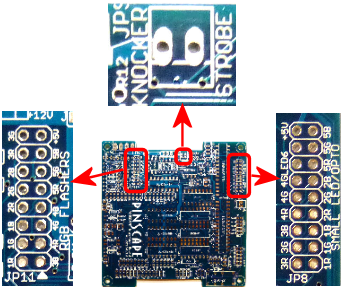
Output ports on the main expansion board.
JP11 (left) is for five RGB flashers; JP9 (top) is for the replay knocker
and strobe; and JP8 (right) is for small (20mA) LEDs.

Warning! Don't connect a strobe or any other output
device to any of the pins on JP12. JP12 is not
an output port header. The printing on the board is so packed
together in that area that it's easy to read the STROBE label as
part of JP12. It's not! The STROBE pin is on JP9, right
next to the KNOCKER pin.
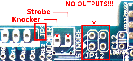
Be careful about where you connect the
strobe and knocker. Both of these connect to the pins on JP9.
Don't connect any output device to JP12. The pins on JP12 connect
directly to GPIO pins on the KL25Z, so connecting them to power
is extremely likely to damage or destroy the KL25Z.
Main board JP11 (RGB Flashers) is designed for high-power RGB
LEDs, for flasher lights. See
Flashers and Strobes for information on
the type of LED most people use. This header has 15 outputs, which is
enough to connect the standard complement of 5 flasher LEDs (as each
RGB LED takes up three channels, one each for red, green, and blue).
The pins on the header are labeled 1R, 1B, 1G, 2R, 2B, 2G, etc. "1R"
stands for the Red channel on the first LED, for example. This is
purely a suggestion for how to connect the color channels; you can
rearrange the connections if necessary. If you connect them according
to the labels, though, it will make the software setup easier, since
this ordering matches the default settings in the firmware.
This connector also provides a +5V power supply pin. The idea is that
you can connect a single 16-wire ribbon cable between this header and
a matching header on your flasher panel to provide all required wiring
for the flashers. This is just here as a convenience; if for some
reason you'd prefer to provide your own power supply connection to
your flasher panel, simply don't connect anything to the +5V pin
on this header.
You don't strictly have to connect flashers to these outputs, although
if you're going to use flashers in your system at all, this is the
best place to connect them. If you're not using flashers,
though, you can re-purpose these outputs for other types of devices,
as long as you stay within the limits of 50V and 1.5A per output.
Don't connect anything that draws more than 1.5A, as that can
potentially destroy the IC chips that drive these outputs. For
anything that takes more than 1.5A, always use the Power Board outputs
instead.
Main board JP9 (Knocker/Strobe) has one pin dedicated to
the replay knocker, and one pin dedicated to a "strobe" output. These
assignments are printed on the board next to the pin header to help
you identify which is which. See
Flippers, Bumpers, and Slingshots and
Flashers and Strobes for notes on these device types.
The strobe output is driven by exactly the same chip that controls
the flasher outputs, so it has the same power limits (50V and 1.5A).
You can use it for other purposes besides a strobe if you prefer,
as long as you stay within those limits.
The knocker output is driven by a MOSFET that can handle very large
loads, which is necessary because real replay knockers are designed
for 50V supplies and draw about 3A. However, it's not great as a
general-purpose output, because it has a "time limit" circuit that
prevents the output from staying on for more than about 2 seconds at a
time. The time limit is specially designed to protect replay knocker
coils against common software faults in Visual Pinball that can leave
devices stuck on; this problem has destroyed replay knockers on more
than a few virtual cabs, but you're relatively immune to this with the
Pinscape boards because of the built-in time limiter circuit. The
downside is that it means that the port is really only suited for a
replay knocker, since you wouldn't want similar time limits on most
other types of devices. The one bit of re-purposing that could be
appropriate for this output is that you could use it for a music
chime, since chime coils have the same vulnerability to overheating that
replay coils have.
See the
warning above about the
proper location of the STROBE output.
Main board JP8 (Small LED/Opto) has 16 pins designed
for low-power LEDs. These are intended primarily for controlling
LEDs in the flipper and MagnaSave buttons; see
Button Lamps
for how to set those up.
As with the RGB flasher header (JP11), these pins are labeled with
color channels - 1R, 1G, 1B, 2R, 2G, 2B, etc. And as with JP11,
you're free to ignore the labels if you prefer, but following them
will save you a little software setup time.
In addition to labeled outputs for 5 RGB LEDs, there's an extra pin
labeled LED6. This is a spare that you can use for an additional
monochrome LED, or just leave unconnected. For that matter, there's
no common use for a 5th RGB LED, since a typical cab only has the four
flipper/MagnaSave buttons. You can repurpose the 5R-5G-5B outputs for
whatever other small LED uses you can think of, and you're free to
treat them as separate channels and connect each one to a monochrome
LED. The RGB-ness is only a suggestion.
This header provides a +5V power supply pin that you can use to
power the attached LEDs.
This header has a special feature for LEDs: it has a built-in current
limiter for each channel, which eliminates the need to use a separate
external resistor for attached LEDs. (See
LED Resistors.)
You can safely connect LEDs directly to these ports, with no resistors
required. The current limit is determined by the resistance (Ohms)
value of resistor "R5" on the main board. If you used the default
2.2K resistor from the parts list, the current limit is set at 20mA,
which is perfect for most small LEDs.
The term "Opto" in the label, by the way, refers to optocouplers.
Optocouplers have internal LEDs with the same general properties as
the small LEDs that these outputs are designed for, so you could
connect an optocoupler to any of these ports in lieu of an LED. That
would allow you to control another circuit through the opto. I don't
have any particular applications for this in mind - it's just an
option for people who like tinkering with electronics, since it gives
you a way to control just about any custom circuit via a Pinscape
output.
Power Board output ports
All 32 of the Power Board outputs are general-purpose, high-power
outputs that you can connect to almost anything. These outputs are
suitable for lights, motors, solenoids, and just about anything else
commonly used in a pin cab. They can handle devices that use power
supplies up to 60V and current up to 4A.
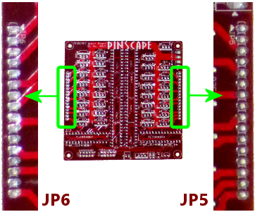
Power board outputs. These are general-purpose
outputs suitable for almost anything in a pin cab. Each output can
handle 4A at 60V.
Chime board output ports
All 8 of the Chime Board outputs are high-power outputs with
time-limiter circuits of the same type used in the replay knocker
output on the main board. As with the replay knocker, these are
designed to protect pinball coils from software faults on the PC that
could leave an output stuck on. They're nominally for "chime units"
(see
Chimes and Bells), but they're really appropriate for any sort
of standard pinball coil, such as bumpers and slingshots. You
wouldn't want to use them with flippers, however, as you certainly do
want to allow flippers to be held on for long periods.
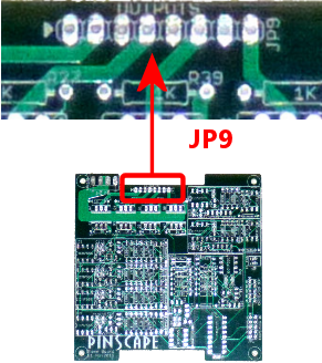
Chime board outputs. These outputs have the
same type of time limiters as in the replay knocker output on the
main board, to protect attached pinball coils from overheating if
the software on the PC crashes and leaves outputs stuck on. Outputs
are automatically turned off if stuck on for more than about 2 seconds.
Each output can handle 4A at 60V.
Power limits
Here's a summary of the power limits for the various outputs on the
expansion boards. The amperage limits are per port.
The Timer column indicates whether or not the output has a timer
circuit that cuts off power after it's been on continuously for more
than a couple of seconds. These apply to the replay knocker output on
the main board and all outputs on the chime board. The timer circuit
is there to prevent software crashes from leaving a pinball coil stuck
"on", which can overheat and destroy those coils. The timed outputs
are good for pinball coils, where you only ever want momentary
activation; they're not good for anything that you actually want to
leave running for long periods, like shaker motors, gear motors, fans,
beacons, lights, etc.
| Board | ID | Description | Max Limits | Timer |
|---|
| Main | JP8 | Small LEDs | 18V | 20-50mA | No |
| Main | JP9 | Knocker | 60V | 4A | Yes |
| Main | JP9 | Strobe | 50V | 1.5A | No |
| Main | JP11 | RGB Flashers | 50V | 1.5A | No |
| Power | JP5, JP6 | General Purpose | 60V | 4A | No |
| Chime | JP9 | Chimes | 60V | 4A | Yes |
DOF Setup
To set up your Pinscape unit with DOF, you of course have to
install DOF on your PC first. See
DOF Setup for instructions.
Once the DOF software is installed, you use the
DOF Config Tool to tell DOF that
you have a Pinscape unit, and to tell it which output ports are
wired to which feedback devices.
- Open the DOF Config Tool in your browser
- Click the My Account tab
- Set Number of Pinscape devices to 1 (or if you have more than one
KL25Z running the Pinscape, select the appropriate number of devices instead).
The number of expansion boards connected to the same KL25Z doesn't matter
here - if you have a main board and two power boards and two chime boards,
you should still enter 1 for Number of Pinscape devices, since
they're all part of the same USB connection from the PC's perspective.
- Set Number of KL25Z devices to 0 (see below
if this seems confusing)
- Save changes
- Go to the Port Assignments page
- Select "Pinscape 1" in the Device drop list
- Go through the port list, assigning each port number in the DOF list
to the device that you wired to the corresponding expansion board port
The port list in the Port Assignments page uses the same port
numbering (Port 1, Port 2, etc) that's shown in the Pinscape Config
Tool output port list. This isn't a physical pin number
from any of the headers. It's the abstract port number from the
output port assignment list.
To figure out what DOF's "Port 1" or "Port 2" means in terms of the
physical expansion board pins, you have to look at the output port
list in the Pinscape Config Tool's Settings page. In the output list,
find the same port number shown in DOF - if you're looking for DOF's
"Port 1", you want the first row, #1, in the Pinscape output list.
Trace across the row to find which physical pin that port is assigned
to. If you want to see a picture of where that pin is physically
located, click the pin name in the row - that will pop up the pin
selector, which will show the pin location highlighted on a picture
of the appropriate expansion board.
The online DOF Config Tool has a confusing
bit of terminology in the device setup section on the "My Account" page.
In the list of devices, you'll find separate entries for "Number of Pinscape
devices" and "Number of KL25Z devices".
For Pinscape boards, use only the Pinscape devices option.
Always leave "Number of KL25Z devices" set to zero (0). This applies whether
you're using the expansion boards or a standalone KL25Z.
This is confusing because the Pinscape software does happen to run
physically on a KL25Z board, so it might seem like you should enter
the same number for both line items. Don't. Pretend that you've
never heard of a KL25Z and that you have zero of them.
The Config Tool has the "KL25Z devices" line item for historical reasons
that date back to the first version of the Pinscape software, when it
was limited to 32 output ports. It should more properly be titled
"Number of Pinscape v1 devices", because that's what it really means.
In any case, just ignore it and leave it set to zero.
