105. Plunger Setup (TCD1103)

Beta Test Alert! This section is new and barely tested. This is a
brand new sensor design added in April 2020, with little or no
field testing so far - just my own lab-bench work putting together the
design. In my testing, it's been performing extremely well, so I'm
publishing the design in the hope that other people will find it
useful as well. But be aware that if you build one, you'll be a very
early adopter. There might be errors or omissions in the plans here
that we'll have to work out. I'd be very interested in hearing from
you if you do build one! Let me know if you run into any problems or
have any ideas to improve the design, and if you actually deploy it,
definitely let me know how it works for you in real everyday use.
The original Pinscape plunger system, first published back in 2015,
was based on a special type of optical sensor called a "linear image
sensor", meaning all of its pixels are arranged into a single row (in
contrast to a normal camera sensor, which has a rectangular array of
pixels). The particular linear image chip we used, known as the
TSL1410R, was an improbably perfect fit - literally - for plunger
sensing, because it consisted of a row of sensor pixels about 3" long,
exactly the length of travel of a standard pinball plunger. By
placing the 3" sensor window adjacent to the plunger, and placing a
light source on the other side of the plunger, the sensor was able to
determine the plunger position by scanning the pixels for the shadow
cast by the plunger along the 3" window.
Sadly, the manufacturer stopped making that 3" sensor a long time ago,
and there's nothing else like it on the market, so this hasn't been an
option lately for new pin cab builds. There are some excellent
alternatives, particularly the AEDR-8300 quadrature
sensor and the sliding potentiometer design.
But none of the other available designs has the special charm of an
imaging sensor, which is that it's completely "non-contact", meaning
that there's no mechanical connection between the sensor and the
plunger, and thus no moving parts to wear out over time. Operating a
standard ball shooter involves a lot of force and high speeds, which
inevitably causes some wear on the sensor parts if they have to be
mechanically connected and move at the same high speeds and jerky
accelerations. (Another non-contact sensor has recently been
added: the VCNL4010 proximity sensor. But
it's not as precise as I'd like.)
That's why I'm pleased to present a new option that brings back the
non-contact, all-optical approach, using a different sensor that you
actually can buy (as of 2020). The new design isn't quite the same as
the old one, because the new sensor is rather different. Whereas the old
sensor had that gigantic 3" pixel array, the new sensor described in
this section has a pixel array that's only about 8mm (about 1/3")
long. But despite its much smaller physical size, the new sensor
actually has more pixels than the old one! Each pixel is just much
smaller, obviously. To bridge the gap between the 3" plunger travel
and the 8mm sensor window, we have to add something the old design
didn't need: optics. We need a lens, to focus an image of the
plunger on the tiny sensor. It's the same principle your iPhone
camera uses to project a tiny image of the Eiffel Tower onto the tiny
CCD chip inside the phone.
The need for a lens makes the system a little more complex than the
old one, which is unfortunate. But the lens has a major upside, too,
which is that a focused image gives us better accuracy in determining
the plunger position. The old "shadow" image was inherently fuzzy, so
it didn't take full advantage of the native pixel resolution of the
sensor. With a lens involved, we can capture a much sharper image,
which lets us determine the plunger position with greater precision.
The new sensor has higher native resolution than the old one to start
with, so when we add in focusing optics, we get a system with
significantly better performance than the old one (which was already
very good).
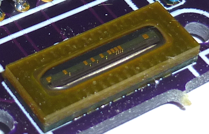
Introducing the TCD1103 sensor
The Toshiba TCD1103 is an optical linear image sensor chip. This is
similar to the image sensor in a digital camera, but rather than
having a rectangular array of pixels like in a camera, the TCD1103 has
all of its pixels arranged into a single row. That's the "linear"
part. To be more specific, the TCD1103 has 1500 pixels in a row about
8mm long.
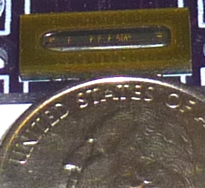
With a US quarter, for scale:
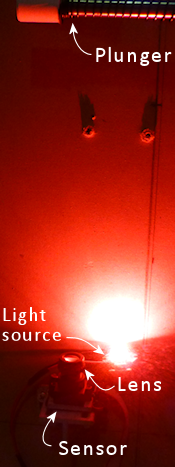
This sensor can be made into a limited sort of optical camera by
fitting it with a lens to focus an image onto the pixel file. We can
use this to track the the plunger position by pointing the camera at
the plunger, with the pixel file oriented along the plunger's axis of
motion. The camera will see an image of the plunger, and as the
plunger moves back and forth, we'll see the image move along the pixel
file. With a little image analysis, the software can figure out where
the tip of the plunger is along the pixel file, which in turn tells us
how far back the plunger is being pulled.
To keep the image analysis simple, we'll set up the plunger so
that it creates a certain image pattern on the sensor.
We'll put a bright white wrapper on the tip of the plunger, so that the
end of the plunger stands out as a clear bright area in the image, and
we'll place a dark (matte black) background behind the plunger, to create
high contrast between the plunger tip and the background. This makes
it easy for the software to find the end of the plunger in the image:
it just looks for the edge between the dark background and the bright
spot at the plunger tip.
This is probably my favorite plunger sensor out of all of the current
options. It can read the plunger position to a very high degree of
precision, thanks to the 1500-pixel resolution of the TCD1103 and the
focusing optics; the plunger position can be reliably determined to
better than one part in a thousand over its range of travel, which
works out to around 1/400 of an inch. The sensor is fast, capturing
images about every 4ms, or 250 times a second, which allows the
software to accurately track the high-speed motion when you pull back
and release the plunger. And it has the inherent "non-contact"
advantage of an imaging system: there's no mechanical contact between
the plunger and the sensor, so there are no moving parts in the sensor
to wear out.
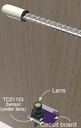
The only disadvantage of this sensor system is that it's a bit complex
to build, in that it requires the lens, a mounting apparatus, and some
extra electronics to interface the sensor to the KL25Z. The plans
presented below include parts lists, 3D-printable designs for the
mounting bracket, and a custom circuit board layout with all of the
interface electronics, so you won't have to improvise any of the
elements yourself. Most of it is just a matter of gathering the
necessary parts from various sources, and we'll give you details on
exactly what to buy and where to look for it. But there is one
special task required that does add a degree of difficulty, which is
that the circuit board uses surface-mount (SMD) parts. That can be a
little intimidating if you haven't done SMD soldering before. If
you're willing to give it a shot, you might find that it's not
actually not that hard, and we include detailed instructions to try to
make it as approachable as possible. But it is a task that many
people find intimidating, so I wanted you to be aware of what you're
getting yourself into.
Bill of materials
This project requires a fairly large set of parts. A few have
to be custom-made, and the rest are off-the-shelf items, mostly
things that are easy to find. Here's the full list:
- Standard pinball plunger assembly; see "Plunger" in Cabinet Parts List for part numbers
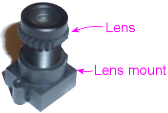
- M12 lens, 16mm focal length, 1/2.7" image format. These can be
found on Amazon and other online vendors for under $10. Make sure to
match our specs for focal length and image format. Some lenses will
list compatibility with multiple image formats; that's fine as long as
1/2.7" is included among the compatible formats.
Note that the figure 1/2.7" is the image format that the lens is designed for, which corresponds to the sensor size. It looks confusingly similar to the "f/" figure that's always quoted with lenses for real cameras, but it's a completely different thing. (The "f/" number is a measure of the lens aperture size, which determines its light-gathering power. It's a dimensionless ratio.) Many of the vendors selling M12 lenses seem to be confused about this, so you might see weird figures like f/2.7" or f/16mm, which are of course bogus. I've also seen "megapixels" figures like 3MP or 5MP, which are meaningless with a lens. If you find a candidate lens whose seller seems too confused to quote the proper specs, you might want to look elsewhere rather than guessing at what the seller really meant.
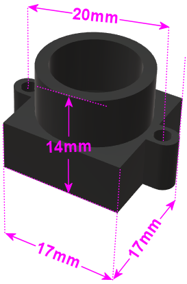
- M12 lens holder with 20mm mounting-screw spacing and an overall
height of 14mm, as depicted in the diagram below. Most of the ones
I've seen for sale match these size specs, but there are some other
sizes available, so check the product dimensions against the diagram.
The mounting screw spacing is critical, to fit our circuit
board and mounting bracket designs, and the height is important
because it affects the range of adjustment for focusing the lens.
Suitable lens mounts are available from Amazon and other online
vendors for about $5 for a pack of 10. (The lens mounting can't be
3D-printed, because the threading patterns for the lens and mounting
screws are too fine.)
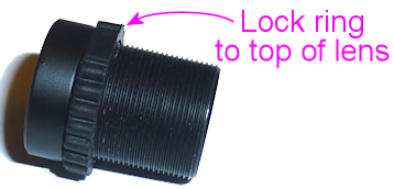
- M12 lock ring, to help keep the lens from moving once you've set the focus properly. M12 lenses usually come with these, but you can also find them as separate parts if needed, on Amazon and other sites. Look for "M12 lock ring".
- 3D-printed mounting bracket. No special materials are needed; any type of plastic print material should produce acceptable results. The design can be printed on a home 3D printer, or by an online service such as All3DP or Shapeways. Ordering it through an online service should run under $10. The plans are available here:
- Custom circuit board. You can have this fabricated by OSH Park, Elecrow, or other PCB makers; we explain the procedure below. The custom board at OSH Park costs about $6.50. The EAGLE plans are here:
- PCB stencil. This is another custom part that you can fabricate from the EAGLE plans for the board, for about $8. This is optional but recommended, since it makes the SMD soldering work much easier. We describe the procedure for ordering a stencil below.
- The electronic components for the circuit board. See
the TCD1103 section in Electronic Parts List.
Important: don't break the seal on the TCD1103 sensor chip's anti-static bag until you're ready to solder. Don't even open it long enough to peek at the chip. The chip is sensitive to ambient humidity, so the packaging was prepared at the factory under super-dry conditions and sealed against moisture. It's important to keep the packaging sealed until you're ready to install the chip. See the "Warning on humidity" below.
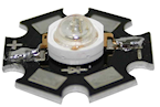 1W red LED, to serve as
a light source. Suitable LEDs are readily available on Amazon and
eBay. I like the "star" LED type depicted at right.
These are fairly easy to solder, and the base serves as a heat
sink and is easy to attach to a mounting bracket. If you happen to
have extra extra 3W RGB star LEDs of the type often used in
flasher panels, you can use one of those, with
just its red channel powered.
1W red LED, to serve as
a light source. Suitable LEDs are readily available on Amazon and
eBay. I like the "star" LED type depicted at right.
These are fairly easy to solder, and the base serves as a heat
sink and is easy to attach to a mounting bracket. If you happen to
have extra extra 3W RGB star LEDs of the type often used in
flasher panels, you can use one of those, with
just its red channel powered.
- A 10Ω, 2W resistor for the LED
- A 1" metal "L" bracket, to serve as a mounting bracket for the red LED. You can find these at any hardware store or home improvement store.
- Thermally conductive paste or tape (also known as "heat sink" paste or tape), for attaching the LED to the "L" bracket
- M2-0.4 x 12mm (also known as 2mm x 0.4mm x 12mm) machine screws, quantity 2, for attaching the lens mount to the bracket. Note that the lens mount I'm using takes M2 metric screws, but some other types might use #2 screws instead (the non-metric sizing system, which is almost but not quite the same size). #2 x ½" should fit if you need the non-metric type. Check the product page for the lens mount you buy, but I've never seen anyone bother to say which type is needed, so you might have to end up guessing. I'd just buy both screw types (M2x12mm and #2x½") to be sure you have the right one on hand when it comes time to assemble everything.
- #6 x 1/2" wood screws, quantity 3, to fasten the sensor bracket and light source to the cabinet wall
Tools for SMD soldering
This circuit board uses all SMD parts, most of which have small,
closely-spaced pin pads - especially the star of the show, the TCD1103
sensor chip. SMD chips are difficult to solder the old-fashioned way
(that is, using a soldering iron to heat each pin and melt solder onto
it individually). In fact, regular soldering is practically
impossible in this case because of the physical design of the TCD1103,
which has all of its pins fully concealed under the chip, with
no exposed metal that you can hit with the soldering iron. Soldering
this type of part requires a whole different technique.
But the "whole different technique" is actually easier than
regular soldering, given the right tools. The industry didn't migrate
to SMD parts to make assembly harder, after all! Granted, the main
motivation was that SMD assembly is easier for robots, but it's also
faster and easier for hand-assembly if you have the right tools.
The right tools consist of:
- SMD soldering paste. Solder paste is the secret
sauce that makes SMD assembly easy. When cold, it's a tacky
paste (as you might guess from the name). It lets you stick
the parts to their assigned places on the board, and holds them
there until the heating step. When heated, it melts
into a combination of liquid solder and "flux", which helps
confine the solder to the metal pads and keeps the solder from forming
shorts to adjacent pads. You just heat up the whole board to
solder-melting temperatures, and all of the parts are
simultaneously soldered to their proper places. It's
almost magic. (This is also what makes it so much easier
than regular soldering: you don't have to laboriously heat
each connection point individually. You just heat the
whole board at once.)
A popular choice that I've seen many people recommend is Chip Quik SMD291SNL50T3, available in 50g tubs for about $17 from Amazon, SparkFun, and other online sites. That's lead-free, so it's somewhat easier on your household air quality than leaded solders. I've also had great luck with MG Chemicals 4860P-35G, although that comes in a tube that's better suited for small jobs with a few pads.
- A solder stencil for the board we're building. This is a plastic or metal sheet with holes etched to match all of the SMD pin pads on the board. It (obviously) has to be custom-made for the board. A stencil isn't absolutely required, as you can apply the solder paste by hand to the individual pads. But it's quite difficult to get the right amount of solder in the right places with a complex board like this one, especially given how tiny many of the pads are. A stencil makes it easy: you position the stencil over the board, align the holes with the pads, smear a glob of solder paste over the whole stencil, and wipe off the excess. This leaves the paste deposited wherever there was a hole in the stencil, which should exactly line up with the pads on the board. You can have the stencil made at OSH Park's sister site, OSH Stencils, for about $8. It increases the overall project cost, but it makes the assembly process so easy and reliable that I think it's well worth it.
- A heat gun. You can also use a toaster oven or a skillet on a stovetop, but for a small board like this, I prefer a heat gun, since it's easy to control and easy to see what you're doing. Specialized heat guns for SMD soldering are available, but they're expensive, and I've found that a cheap hardware-store heat gun works just fine for a small board like this one. I have a heat gun from Harbor Freight Tools that cost about $20, which I've successfully used to solder many small SMD boards.
- Tweezers or forceps. Optional, but very helpful for manipulating small parts. I found a pair of anti-static tweezers on Amazon (Vetus Pro ESD-safe fine-tip curved tweezers, model ESD-15, $2-$10 from various Web sellers) that have worked well for me.
- PCB jigs. Optional; you can also just use some spare blank circuit boards if you have them. These are just some plastic pieces the same thickness as the circuit boards (typically 1.6mm) to place around the board to keep in place while you're working with the stencil. It's the thickness that counts, which is why spare blank circuit boards work as improvised jigs; the idea is to make a flush surface around the edges of the boards with something of the same thickness. If you order the stencil from OSH Stencils, they'll throw in a jig set for $6.
- Solder paste spatula/spreader. Professional metal and plastic spreaders are available at professional prices, but most hobbyists just use something improvised, like a putty knife from a hardware store. Old expired credit cards are supposed work pretty well, too. OSH Stencils throws in a credit-card sized plastic spreader as a freebie with each order.
Order the circuit board
The EAGLE plans for the board are available here:
Since this board is small, I'd highly recommend OSH Park if you're in
the US. They're inexpensive, fast, top quality, and their
ordering process is delightfully easy:
- Open the OSH Park site in your browser
- Upload the .brd file from the EAGLE plans linked above
- Click through to the ordering page and place the order
OSH Park will send you three copies of the board for about $6.50.
Ordering from other vendors: If you prefer to order the boards
from Elecrow or another PCB vendor, the process is a little more
complex. Other vendors don't usually accept EAGLE .brd files like OSH
Park does. Instead, they require you to upload a format known as
"Gerber" files. The reason we don't just include the Gerbers in the
ZIP is that they have to be generated separately for every PCB maker,
using a "design rules" file provided by your chosen manufacturer. You
use EAGLE to generate the Gerbers once you have the design rules file
from your PCB vendor. It's easier than it sounds, but requires a
couple of extra steps on your part. The full procedure is explained
in Fabricating the Expansion Boards. Follow the instructions there, using the
.sch and .brd files from the ZIP download linked above. That chapter
also has tips on selecting a PCB vendor, and instructions on how to
place an order with the typical vendors. You can use the same PCB
manufacturing options recommended in that chapter for the expansion
boards - the same options will work equally well with the sensor
board.
Order an SMD stencil
As mentioned earlier, I highly recommend using a stencil to aid in the
SMD soldering for this project. This circuit board has a lot of small
and closely-spaced pads; it's difficult to get the solder paste in the
right place by hand. A stencil adds to the cost, but it makes the
solder paste placement easy and reliable. You're much more likely to
be successful on the first try with this board if you use a stencil.
You can order a stencil from OSH Park's sister site,
OSH Stencils. Or, if you're
having your boards made by Elecrow
or another PCB maker, you can have them make the stencil along with
the board order. (Note that you can always mix and match vendors,
too. OSH Stencils might be cheaper for the stencil even if you order
the board from Elecrow, so I'd check pricing at both sites before
finalizing your order.)
The ordering process at OSH Stencils is a little more complex than OSH
Park's, but it's not too difficult:
- Go to OSH Stencils in your browser
- Click Upload design and select the .brd file from the ZIP linked above. You might be prompted to create an account or log in, so that the upload can be stored for later access.
- In the uploaded file list, you should see three entries, with suffixes .gbp (bottom stencil), .gtp (top stencil), and .gko (board outline).
- The bottom stencil (.gbp) for this project is empty, so you should simply delete it from the list by clicking the big red X at the right
- Make sure that the other two are set to their proper types in the drop lists: .gtp should be top stencil and .gko should be board outline. The site usually gets these right automatically, but check, and change the drop list settings if they don't already match.
- In the Project name box at the top left, enter a name for the project, and click Create Project
- In the Project Name column of the file list, set each project to the new project name
- Click Generate Stencils at the top right
- This will take you to a Projects list view. Click on the project name in the list to open it, then click on the Top Stencil item to preview it. The preview layout should look like the arrangement of solder pads on the board.
- In the Stencil Settings, select your preferred options for the stencil.
You can read about the various options in the site's help/FAQ pages, but
here's what I'd recommend:
- Material type: Polyimide film, 5mil
- Border size: 0.75
If you plan to mass-produce the board, you'll want to upgrade the material to stainless steel. It's durable enough to make probably hundreds of copies, but it'll add about $5 to the cost. Polyimide is a plastic film that's cheaper but less durable; it's what I'd choose if you only plan to make a few copies.
- Click Add this Stencil to Cart at the top right
- Go to the cart and check out to complete the order
Ordering stencils from other PCB vendors: If you're ordering
the PCBs through Elecrow or another vendor, they usually give you the
option to also make the SMD stencils as part of the order. That's a
"checkbox" option with most of the other PCB vendors - you just check
a box on the order form saying you want to include the stencils, and
they automatically generate the stencils from the same Gerber files
you prepared for the PCBs. There will probably be some other options
that you have to choose, such as stencil material, thickness, border
size, and whether or not a "frame" is included. Since this is a small
and relatively simple board, I'd just choose the cheapest options. In
any case, you don't need a frame - frames are mostly for
factory machines that apply the solder paste mechanically, and since
those are industrial equipment with $100K+ price tags, I'm going to
guess you don't have one at home. (And if you do, you know way more
about PCB stencils than I do!)
Fabricate the 3D-printed bracket
The plans for the mounting bracket can be downloaded here:
No special materials are required for this print job. You can print
this on a home printer, or use any online vendor. I've had great
results with All3DP lately; they have
a pricing engine that gets quotes from several vendors, which found
good prices for the parts I've tried. I've also used
Shapeways for several projects,
and I've always had good results with them.
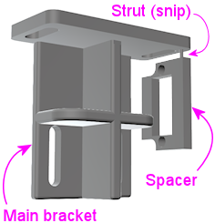
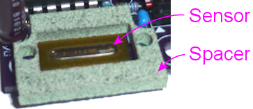
The printed part actually has two components, printed together into a
single block using the "model airplane" approach. The main component
is the bracket itself, and the smaller attached component is a spacer
that goes between the circuit board and the lens mount, to position
the lens mount properly above the sensor chip. To separate the two
parts, use scissors or wire cutters to snip the little plastic strut
connecting them. You can trim off and discard the strut.
Install the plunger
While you're waiting for the circuit board and 3D print job to arrive,
you can get the plunger itself set up in your cab. The sensor doesn't
have any mechanical connection to the plunger, so you don't have to
wait for the rest of the parts to install the plunger. There's also
nothing special you have to do to install it; just set it up like a
regular pinball plunger. See "Plunger" in
Cabinet Hardware Installation for assembly instructions.
Set up a reflector on the plunger
We have to make one small modification to the standard plunger
assembly. We're going to replace the standard rubber tip that's
normally included in a real plunger with a reflective paper cylinder.
This cylinder will serve as a reflector, which will show up as a
clear, bright region in the image on the sensor.
We use the paper reflector for a few reasons. One is that white paper
is more reflective than the white rubber they use in the plunger tips,
so we'll get a brighter image with a paper reflector. Another is that
the rubber tips are rounded at the end, and we'll get a shaper edge in
the image (which is what the software looks for) with a squared end.
A third reason is that we can make the paper reflector a little bigger
than the rubber tips, which will give us more leeway in aiming the
lens, which makes installation easier.
- Remove (or skip installing) the rubber tip at the end of the
plunger. If you bought complete ball shooter assembly with the rubber
tip already installed, you can remove it simply by pulling it off the
end; it's just held on by friction.
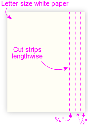
- Grab some ordinary white paper, letter size
- Cut three strips lengthwise: 1/2", 1/2", and 3/4"
- Using cellophane tape or masking tape, tape one end of one of the
1/2" strips to the plunger tip, aligning one edge of the paper with
the e-clip that holds the spring on.
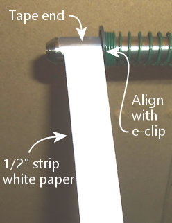
- Tightly wrap the strip around the plunger to form a cylinder.
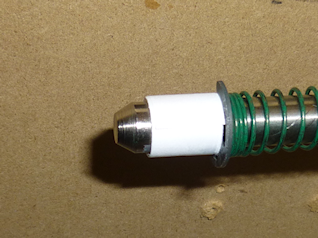
- Tape down the end of the strip
- Repeat with the second 1/2" strip
- Repeat with the 3/4" strip
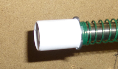
- You should now have a 3/4"-long paper cylinder at the end,
about the same diameter as the e-clip
- Check clearance with your flipper switches by pulling the plunger
all the way back and making sure that the paper cylinder doesn't catch
on the switches. If you don't have enough clearance, you can try
wrapping the paper strip a little more tightly, or you can trim a
little of the length off one of the strips and re-wrap it.
Q: "Why the different strip widths?" A: To make the outer edge
sharper. We want the sensor image to see a sharp edge at the end of
the plunger, so that the software can identify the boundary between
the plunger and the dark background as clearly as possible. A clear,
sharp edge in the image makes the position reading more accurate and
stable. I noticed that if you make the whole strip the same width,
some of the inner windings can poke out a bit beyond the end of the
overall cylinder, which can make the edge a little softer in the
image. Making the inner layers narrow makes them less likely to jut
out.
Q: "Why isn't this a 3D-printed part?" A: It certainly could be! But
I figured it would be better to save the extra expense given that it's
easy enough to craft this out of paper. Plus, the point is to create
a reflective surface that will show up well in the sensor images, and
white paper is a better material for that.
Install a dark backdrop above the plunger
The next step in setting up our little photo studio is to is to place
a dark backdrop behind the plunger. And by "behind", we really mean
"above", because the camera is going to be positioned near the floor
of the cab pointing up at the plunger.
The dark backdrop is there to ensure that the white reflector we just
installed at the end of the plunger stands out with good contrast in
the sensor images. That'll make it easier for the software to get a
solid reading on the plunger position when analyzing the sensor
images.
All you need to do is to install some matte black material just above
the plunger. Be sure to use something with a matte finish, not
anything shiny. Black felt is probably the ideal choice, but
black construction paper also worked well in my tests.
I'll leave the details of how to install this up to you, since the
most convenient arrangement will depend on how your cab is laid out.
You'll almost certainly have something already positioned just above
the plunger - either the underside of your TV, or the bottom of your
"apron". Whatever is there, it should be enough to fasten black paper
or black felt to the bottom of it. I'd try to cover the whole area
around the plunger, from front to back and about an inch on either
side.
If you have lights in your flipper buttons, you might also consider
installing something to block that light, so that it doesn't hit the
black backdrop. That probably isn't strictly necessary, but given
that this is an optical sensor, the less stray light the better.
Warning on static electricity
As with many electronic parts, the TCD1103 is sensitive to static
electricity. This chip is actually very sensitive to static,
even more so than most other components, so please take extra care
handling it. All of the normal procedures needed for any
static-sensitive parts apply (see Static Electricity Precautions), but I'd
be extra vigilant with this part because of its high sensitivity.
Warning on humidity
As though static electricity weren't enough to worry about, the
TCD1103 chip is also sensitive to humidity - at least, it is during
the soldering process. After soldering the part, humidity won't
affect it, so you don't have to worry about ongoing problems if you
live in a humid climate. But humidity is a big issue for this type of
chip during the soldering process, because of the high temperatures
involved. Any moisture that leaches into the chip's plastic casing
can form steam bubbles when the chip is heated for soldering, and
these can vent explosively, cracking the plastic case and destroying
the internal wiring and silicon parts.
When you buy this chip from a reputable vendor like Mouser or DigiKey,
they'll ship it in a sealed, moisture-proof plastic bag, which keeps
the chip dessicated during storage. Don't open the bag until
you're ready to solder the chip, to ensure that it's not exposed
to ambient humidity too early.
The packaging should include an indicator card (sealed inside the
moisture-proof bag with the chip), with chemical indicator spots that
turn different colors according to humidity exposure. When you first
open the bag, immediately check the indicator card to make sure it
shows the proper color (instructions will be printed on the card).
The indicator card is there to ensure that the seal on the bag was
intact throughout the storage period, so as long as it shows the
proper color when you first open the bag, the chip is safe to solder.
(Note that the indicator card will start changing colors quickly after
you open the bag, since your house is almost certainly more humid than
the dessicated conditions required for storage. That's okay! The
card isn't there to check your house's humidity; it's there to assure
you that the package seal wasn't broken during storage. It's only
important to check the indicator when you first open the package.)
Once the packaging is opened, the part will start absorbing ambient
moisture from the air, but fairly slowly. It remains safe to solder
for up to 120 hours (five days) after opening the bag. This
assumes that your ambient relative humidity level is 60% or below; if
you live in an especially humid area, the safe period will be shorter.
The best bet is always to keep the bag sealed until just before you're
ready to assemble the board. And no need to panic or rush once you
do; you'll certainly be safe for several hours no matter how humid
your climate is.
I wouldn't count on moisture-proof handling and packaging if you
bought from a cheaper source like eBay or Aliexpress. If there's no
indicator card enclosed, you should use the baking procedure
described below to be safe.
"Baking" procedure: If you have a chip that wasn't kept in
moisture-proof conditions during shipping and storage, there's a
fairly simple procedure called "baking" that you can use before
soldering to make sure it's free of moisture. You should do this if
any of these apply:
- Your chip didn't come with a moisture indicator card in the packaging
- The indicator card showed excessive moisture when you opened the package
- You opened the packaging but didn't complete soldering within 120 hours
(less if you live in an especially humid climate)
The procedure for baking the chip is simple. You just need to pop
it in an oven, toaster oven, or under a heat lamp, where you can maintain
a temperature of 125° C (about 250° F) for 24 hours. After
keeping it in a 250° F environment for 24 hours, take the chip out
and let it cool.
The baking procedure will gently release any trapped moisture. After
baking, the chip is once again safe for soldering, and should remain
so for up to 120 hours, as though you had just taken it out of its
original factory packaging.
Build the circuit board
Be sure to read the sections above about static electricity and
humidity dangers. Please observe all of the precautions
diligently - the TCD1103 can be easily destroyed by improper handling.
This board uses surface-mount parts, so it can be a little
intimidating if you haven't done SMD soldering before, but it's not as
hard as it might seem. If you're new to this, you might want to take
a look at a tutorial or two to get an idea of what's involved and some
tips on technique; try a Web search for "SMD stencil tutorial". I'd
once again recommend using the stencil with this project because of
the small parts involved.
The SMD stencil soldering process works like this:
- Set up your work area on a large flat surface, like a workbench
or kitchen table
- Put down a fairly large pice of cardboard or heavy paper (butcher
paper, for example)
- It's easiest to hold everything in place using a PCB jig set -
acrylic corner pieces the same thickness as the board, that you can
place around the board to keep it from sliding around and to form a
uniform flat surface for a couple of inches around the board's
perimeter. You can also use some spare boards for this, placing
them around the perimeter of the board you're building.
- Tape down the board and the jig pieces to the work surface, using
masking tape. Be sure not to cover up any of the SMD pads on the
subject board with tape.
- Place the stencil over the board and line up the holes in the
stencil with the solder pads on the board. Tape it down to
the work surface (leaving all of the holes uncovered, of course).
- Scoop a big glob of solder paste onto the board on one side
- Use the spreader to smear it across the board to the other side
to form a thick layer, pressing it down as you go to force it
through the holes
- Now do another sweep with the spreader in the reverse direction,
this time scraping off as much of the top layer as you can, so
that the only paste remaining is the paste that squeezed through
the holes. Return the excess paste to the tub.
- Carefully peel the stencil off of the board
- Clean any remaining paste off of the stencil and return it to
the tub
- You should now have a nice clean layer of paste on each of the
solder pads on the board. Check the alignment to make sure that the
pads line up reasonably well. You don't have to get the alignment
perfect! Solder paste is very forgiving; its affinity for the metal
pads will make it ball up nicely on the pads when heated even if you
got a fair amount outside the lines.
- Place the parts! Use tweezers for the smaller parts.
- Match the parts to the pads on the board using the
"designator" - R1, C1, etc
- As you place the parts, press down on them gently with
the tweezers to stick them to the paste
- Resistors aren't polarized, so it doesn't matter which
direction they go
- Capacitor C1 isn't polarized, so its orientation doesn't matter
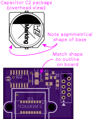
- Capacitor C2 is polarized, so its orientation does matter.
The part's plastic base has an asymmetrical shape that serves as the orientation
guide. Match the shape to the outline printed on the board.
- The transistor's (Q1) orientation should be obvious from
the pad layout
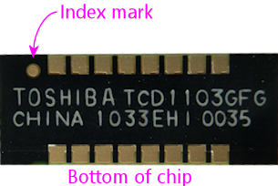
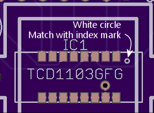
- Make sure that the sensor chip is oriented correctly: the
white circle printed on the board in the corner of the corresponds
to the "index" mark - a dot - printed on the bottom
of the chip next to pin 1. Note that the index mark is printed
on the bottom of the chip, so you'll have to do a little spatial
reasoning to keep track of where it goes when you flip the chip over.
- The other IC chip (IC2) also needs to be oriented properly,
in this case by matching the little half-moon notch on the chip
to the notch printed on the circuit board outline
- Once all the parts are placed, it's time to solder. The basic
pattern for SMD soldering is to heat the whole board
gradually for about 60 to 120 seconds,
so that nothing cracks or pops from thermal expansion, then keep it
hot enough to melt the solder for about 30 to 60 seconds. The natural
surface tension of the melted solder will make it flow over the pins and pads,
so the goal is simply to melt the solder across the whole board for long
enough for this flow process to happen. Then we can let the board
cool, again going gradually to avoid thermal shock.
Everything should freeze into place as the solder sets.
I prefer the heat gun method:
- Remove the board from the work surface and put it on something heat-safe
- Set the heat gun to low
- Point the gun at the board and hold it about an inch from the board,
straight above
- Make small circles over the board to heat the board evenly
- Do this for about 60 seconds. This is the ramp-up phase - we're trying
to heat the board gradually here so that there's no thermal shock.
- Set the gun to high, continuing to point it at the board and make small circles
- Watch the solder paste; in 30-60 seconds, it should start melting; it'll
change from the dull gray paste color to bright silver
- Once all of the solder is melted, continue heating for about 10 or 20 seconds more
to let the solder flow over the pins and pads
- Now gradually back the gun away from the board - two inches for a few
seconds, three inches for a few seconds, etc. Keep going like this for
about 30 seconds.
- Turn off the gun
- Let the board cool
- Once the board has cooled, there's still one part that has to be
soldered the old-fashioned way, namely the ribbon cable connector.
Insert that through the holes and solder the pins on the bottom
side of the board. Be sure to protect the TCD1103 while the
board is flipped over, by putting down some cardboard or paper
on the work surface.
You can skip the ribbon cable connector if you plan
to use hook-up wire instead of a ribbon cable. I'd recommend
the ribbon cable with this board, not only because it's easier
(in my opinion), but because it makes a cleaner signal path
for the high-speed data signals this sensor uses.
Install the ribbon cable
Remember to continue being careful about static electricity while
handling the board. The CCD chip remains sensitive to static even
after soldering. (Humidity is no longer a worry after soldering,
though.)
If you're using the ribbon cable connector, the next step is to attach
the cable. You should already have soldered the connector to the
board (see above). The connector comes in two pieces: a base with the
pins sticking out, and a clip that fits over the top. The base is the
part that you solder to the board. If you separated the top clip part
during soldering, put it back, but only loosely - you want to leave a
bag between the two parts big enough for the cable. If the clip is
still in place, loosen it to open up a gap for the cable.
 Slip the ribbon cable into the opening. If your cable has a stripe
down one side (usually red), oriented the cable so that the stripe is
on the side with the little white triangle printed on the circuit
board. The triangle printed on the board and the stripe on the cable
both represent "pin 1" in the wiring.
If your cable doesn't have a stripe, you should add one with a
red marker. It's best to use a permanent marker with oil-based
ink for this, because water-based inks tend to rub off of the
plastic insulation too easily. Draw a stripe down the whole length of
the cable along one side. (It doesn't matter which side you pick.)
The cable should just barely fit into the gap in the connector. This
is part of the design, to make sure the cable is positioned properly
side-to-side. Let the end of the cable extend about 1/4" past the
clip.
Once the cable is positioned properly, get out some pliers. There's
actually a specialized IDC crimper tool for this job, but ordinary
pliers work well enough if you're careful. Carefully apply pressure
to the top of the clip. Start at one side of the clip, push it down
just a little bit there, then gradually move to the other side. Work
back and forth a few times until the clip is all the way down and
snaps into the locks. It's better to do this gradually so that you
force the wire down fairly evenly and keep it close to level
side-to-side.
Be careful not to dislodge the soldered pins on the bottom of the
board! If you have a spare copy of the board, you can put the spare
board under the assembled board, with the connector pins going through
the holes in the spare board. This will let you apply pressure to the
bottom of the board without applying pressure to the bottom of the
pins.
Finally, install the IDC connector at the far end of the cable.
This is the plug that connects to the expansion board header. This
is almost exactly like attaching the soldered connector.
Be sure to line up pin #1 on the plug with pin #1 on the cable. On
the plug, you should find a small triangle or arrow at one corner,
embossed in the plastic. (It can be hard to spot since it's just a
little bump, but it should be there.) That's the pin #1 side.
Make sure that lines up with the red stripe on the cable. When
you plug the cable into the expansion board, this side should also
line up with the triangle printed on the expansion board next to
the header, which is yet another pin #1 marking.
Slip the ribbon cable into the opening. If your cable has a stripe
down one side (usually red), oriented the cable so that the stripe is
on the side with the little white triangle printed on the circuit
board. The triangle printed on the board and the stripe on the cable
both represent "pin 1" in the wiring.
If your cable doesn't have a stripe, you should add one with a
red marker. It's best to use a permanent marker with oil-based
ink for this, because water-based inks tend to rub off of the
plastic insulation too easily. Draw a stripe down the whole length of
the cable along one side. (It doesn't matter which side you pick.)
The cable should just barely fit into the gap in the connector. This
is part of the design, to make sure the cable is positioned properly
side-to-side. Let the end of the cable extend about 1/4" past the
clip.
Once the cable is positioned properly, get out some pliers. There's
actually a specialized IDC crimper tool for this job, but ordinary
pliers work well enough if you're careful. Carefully apply pressure
to the top of the clip. Start at one side of the clip, push it down
just a little bit there, then gradually move to the other side. Work
back and forth a few times until the clip is all the way down and
snaps into the locks. It's better to do this gradually so that you
force the wire down fairly evenly and keep it close to level
side-to-side.
Be careful not to dislodge the soldered pins on the bottom of the
board! If you have a spare copy of the board, you can put the spare
board under the assembled board, with the connector pins going through
the holes in the spare board. This will let you apply pressure to the
bottom of the board without applying pressure to the bottom of the
pins.
Finally, install the IDC connector at the far end of the cable.
This is the plug that connects to the expansion board header. This
is almost exactly like attaching the soldered connector.
Be sure to line up pin #1 on the plug with pin #1 on the cable. On
the plug, you should find a small triangle or arrow at one corner,
embossed in the plastic. (It can be hard to spot since it's just a
little bump, but it should be there.) That's the pin #1 side.
Make sure that lines up with the red stripe on the cable. When
you plug the cable into the expansion board, this side should also
line up with the triangle printed on the expansion board next to
the header, which is yet another pin #1 marking.
Connect and test
Before installing the sensor in the cabinet, it's a good idea to
connect it to the KL25Z and test it out, to make sure the hardware is
working correctly. This will also let you use the Config Tool's
plunger sensor viewer to view the live images coming in on the sensor,
which you'll need to be able to do during the installation process to
aim and focus the lens.
Before connecting the sensor, it's a good idea completely unplug the
KL25Z to remove power. You should unplug the KL25Z USB cables even if
the PC is powered off, because most PCs continue to power USB devices
even when the main PC power is off.
Continue to be careful about static electricity when working with the
sensor board. The CCD chip is highly static-sensitive even after
soldering.
Connect to the expansion boards
If you're using the Pinscape expansion boards, simply plug the
ribbon cable connector into the main expansion board's "Plunger"
header. Be sure to line up the "pin 1" triangle printed on the
expansion board with the red stripe on the cable.
Connect to a standalone KL25Z
If you're using a standalone KL25Z, I'd still recommend using
the ribbon cable connector. That provides a cleaner signal path
than ordinary hook-up wire would, which is important for this
sensor because it uses high-speed data signals. The easiest
way to connect the ribbon cable to a standalone KL25Z is using
the plunger sensor breakout board:
- Plug the ribbon cable into one header on the breakout board (it
doesn't matter which one), lining up the red stripe on the cable
with the "pin 1" triangle printed on the board
- Connect the pins on the other header on the breakout board as follows:
- Breakout board 3.3V to KL25Z P3V3 (pin 8 on J9)
- Breakout board GND to KL25Z GND (pin 12 or 14 on J9)
- Breakout board D0 to Kl25Z PTE21 (pin 3 on J10)
- Breakout board B0 to KL25Z PTB0 (pin 2 on J10)
- Breakout board E20 to KL25Z PTE20 (pin 1 on J10)
- Breakout board D5 to KL25Z PTE22 (pin 5 on J10)
If you're already using some of those GPIO pins for other purposes,
you can use different pins for the sensor connections, with a few
constraints. First, the wire that we connected to PTE21 requires a
PWM-capable pin. Second, the wire we connected to PTB0 requires an
analog-input (ADC) pin. The other two connections (the ones assigned
to PTE20 and PTE22) don't have any special requirements, so they can
be reassigned to any free GPIO pins. The Config Tool will show you
the allowable GPIO ports for each connection when you configure the
sensor in the Settings page, and you can also check
KL25Z Pin Out for the full list of GPIO pin capabilities.
Configure the software
- You should have the sensor connected to the KL25Z at this point, as
explained above
- Connect the KL25Z to the PC using USB cables as normal
- Bring up the Pinscape Config Tool on the PC
- Go to the Settings page
- Scroll down to the plunger setup section
- In the Plunger Type drop list, select TCD1103
- If you're using a standalone KL25Z, check that the GPIO pin
assignments match your wiring. If you didn't use the default pin
assignments, click on the pin name boxes and update the pin
assignments to match the pins you actually wired. Note that the "fM
(Master Clock)" and "OS (output signal)" connections have special
requirements that limit the choice of GPIO pins; the Config Tool will
show you the valid pins for those. If you wired those connections to
GPIO pins that aren't allowed, you'll have to change wiring to valid
pins as shown in the Config Tool.
- If you're using the expansion boards, there's no need to select
the pin assignments, since they're pre-determined in the expansion board wiring
- At the bottom of the page, click Program KL25Z to save the
changes to the KL25Z firmware
Initial testing
We won't be able to get sharp images on the sensor until we install
the lens, which we'll come to shortly, but we can at least do some
rough initial testing to see if the sensor is responding to light at
all. Basic light reception is good enough to verify that the
soldering process was successful and that the software is configured
correctly. I find it very helpful to do these tests before attempting
the full installation, so that I don't have to wonder if the basic
wiring is working while trying to align the lens.
- Return to the main page in the Config Tool
- Click on the Plunger icon to bring up the plunger viewer
Note: During testing, don't point any light sources directly at
the sensor. Overexposing a CCD can cause a cascade effect that maxes
out all of the pixels and gets them stuck like that until you reset
power. Ambient light in a normally lit room should be enough to
see a response on the sensor.
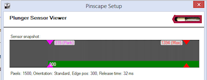
The plunger viewer shows the image being received on the sensor.
Remember that this sensor only has a single row of pixels, so you
shouldn't expect to see a full rectangular image like on a normal
camera. Instead, the image is just a single line of pixels. The
viewer screen expands this into a wide bar, but at each point along
the bar (left to right), you're only seeing a single pixel value.
Without a lens installed, the image is so unfocused that it can really
only show the ambient light level. The CCD sensor is extremely
sensitive to light (especially at the red end of the spectrum), so if
the sensor is sitting out in the open and you have the lights on in
the room, the whole viewer should look fairly uniform, from dark gray
to light gray, depending on how bright the ambient light in the room
is. (Don't pay any attention to the green bar; without a lens to form
a focused image, the software can't get a good read on the plunger
position, so the green bar will probably jump around randomly.)
 Typical snapshot with the sensor working. The pixels appear with
a fairly uniform shade of gray. This particular snapshot has the
sensor in a shaded area, so it's not picking up much light.
With more ambient light, the pixels will be lighter gray or
closer to white, but should still look fairly uniform. If the
pixels look "noisy", with a lot of variation from one pixel to
the next and a lot of rapid fluctuation, there might be a problem
in the wiring or pin assignments.
The most basic test you can do is to completely cover the sensor with
something opaque. You should see the sensor view change to darker
gray, still fairly uniform across the image. Uncovering the sensor
should return to a lighter gray or white image. It's okay if it's not
completely black when covered and not completely white when uncovered.
The important thing is to see a clear response to different light
levels - brighter pixels when the sensor is exposed to light, darker
pixels when it's shaded.
Another test you can try is to cover a portion of the sensor, using an
opaque piece of thick paper or cardboard. If you cover a portion of
the sensor window (holding the paper right up against the sensor), you
should see a corresponding section of the pixels in the viewer window
darken. Without a lens, you'll only be able to see a very coarse and
blurry image, but it should still be possible to see that a section of
the sensor is shaded.
If you see the expected responses to these tests, the sensor is
working! You can proceed to the cabinet installation below. If the
sensor doesn't respond as expected, the first troubleshooting step is
to confirm that all of the GPIO pins for the sensor are assigned
correctly in the Settings page. Carefully check each pin assignment
against the physical wiring - the sensor won't work at all if even one
pin assignment is wrong. (Incorrect pin assignments shouldn't cause
any permanent damage to the electronics, though.)
If the pin configuration looks right, you might try a power cycle
reboot of the KL25Z. Overexposing the sensor beyond a certain point
can cause a cascade effect that blinds all of the pixels, which can
last until you power cycle the chip. That's something you can do by
accident when you're handling the board during testing, so it can be
worth trying a power cycle reset.
If the pin assignments are all correct and power cycling doesn't help,
you probably have a problem in the soldering. Check all of the solder
joints carefully (I'd use a magnifying glass). If you spot any solder
joints that don't look properly connected, you can try using a
fine-tipped soldering iron to heat the joint long enough to melt the
solder. That's often all you need to do to fix a bad SMD joint - the
natural surface tension in the melted solder will usually "heal" a bad
joint.
Typical snapshot with the sensor working. The pixels appear with
a fairly uniform shade of gray. This particular snapshot has the
sensor in a shaded area, so it's not picking up much light.
With more ambient light, the pixels will be lighter gray or
closer to white, but should still look fairly uniform. If the
pixels look "noisy", with a lot of variation from one pixel to
the next and a lot of rapid fluctuation, there might be a problem
in the wiring or pin assignments.
The most basic test you can do is to completely cover the sensor with
something opaque. You should see the sensor view change to darker
gray, still fairly uniform across the image. Uncovering the sensor
should return to a lighter gray or white image. It's okay if it's not
completely black when covered and not completely white when uncovered.
The important thing is to see a clear response to different light
levels - brighter pixels when the sensor is exposed to light, darker
pixels when it's shaded.
Another test you can try is to cover a portion of the sensor, using an
opaque piece of thick paper or cardboard. If you cover a portion of
the sensor window (holding the paper right up against the sensor), you
should see a corresponding section of the pixels in the viewer window
darken. Without a lens, you'll only be able to see a very coarse and
blurry image, but it should still be possible to see that a section of
the sensor is shaded.
If you see the expected responses to these tests, the sensor is
working! You can proceed to the cabinet installation below. If the
sensor doesn't respond as expected, the first troubleshooting step is
to confirm that all of the GPIO pins for the sensor are assigned
correctly in the Settings page. Carefully check each pin assignment
against the physical wiring - the sensor won't work at all if even one
pin assignment is wrong. (Incorrect pin assignments shouldn't cause
any permanent damage to the electronics, though.)
If the pin configuration looks right, you might try a power cycle
reboot of the KL25Z. Overexposing the sensor beyond a certain point
can cause a cascade effect that blinds all of the pixels, which can
last until you power cycle the chip. That's something you can do by
accident when you're handling the board during testing, so it can be
worth trying a power cycle reset.
If the pin assignments are all correct and power cycling doesn't help,
you probably have a problem in the soldering. Check all of the solder
joints carefully (I'd use a magnifying glass). If you spot any solder
joints that don't look properly connected, you can try using a
fine-tipped soldering iron to heat the joint long enough to melt the
solder. That's often all you need to do to fix a bad SMD joint - the
natural surface tension in the melted solder will usually "heal" a bad
joint.
What it looks like if it's not working
The typical appearance if the sensor isn't wired correctly is a
"noisy" image - pixels radpily fluctuating with different shades of
gray, and random variation from one pixel to the next. The KL25Z
reads pixels from the sensor through a GPIO analog input pin, so if
the sensor isn't working, the analog pin will typically read random
electrical noise, which shows up in the visualization as random and
rapidly changing pixel brightness. When the CCD is working, the pixel
readings tend to be stable over time and vary smoothly across nearby
pixels.
If the pattern on the image viewer isn't "noisy", but doesn't respond
as expected to changing light levels or to a partially covered sensor
window, the sensor might actually be working; the problem might simply
be that your ambient lighting is too strong or too weak. In other
words, you might be overexposing or underexposing the sensor. If the
sensor viewer is showing a uniform dark gray or black, try increasing
the ambient light level in the room, and repeat the basic tests; if
it's showing uniform bright gray or white, try decreasing the ambient
light level.
Wire the light source
For the light source, I recommend a 1W red LED of the "star base"
type. You can find these on eBay and Amazon.
A 3W RGB LED will work equally well, because that's a combination of
1W red, blue, and green LEDs in a single housing. You can just wire
up the red segment and leave the blue and green segments unused, which
will make the light the same as a 1W red LED. Note that it might seem
like powering the other segments could only be better in terms of
providing even more illumination, but I'd actually recommend against
that because we don't want to overexpose the images. 1W worth of red
light seems to be just about the perfect amount in my testing.
The reason we use a red LED as the light source is that the TCD1103's
peak sensitivity is at the red end of the visible spectrum. The
sensor actually responds to light across the whole spectrum, so it's
not absolutely required that we use a red light source; it's just that
it's most sensitive to red light, so a red light source is the most
efficient. We might need more power with a blue light to get a good
exposure level.
- Figure how long a wire you'll need to reach from the light source,
which will be installed at roughly the front right corner of the
cabinet, to a connection point for your 5V power supply
- Cut a length of red hook-up wire and a length of black wire long
enough to reach
- Strip about 1/4" of insulation from each end of each wire
- Solder one end of the red wire to the "+" pad of the star LED (or
the "R+" or "RED+" pad, if you're using an RGB LED). As always, the
best soldering technique is to hold the wire and pad firmly together,
press the soldering iron tip against the junction, wait a few seconds
for the parts to heat, and then touch the solder to the parts
(not the soldering iron tip) until the solder melts and flows
freely over both the wire and pad. Then remove the soldering iron tip
and let the joint cool for about 10 seconds while holding everything
perfectly still. For joining loose parts like this, I find it's a lot
easier if you use clamps or paperweights to hold everything in place
while you're working.
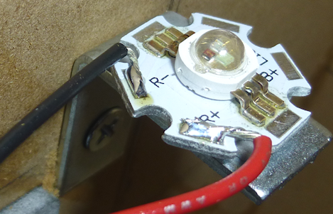
- Solder one end of the black wire to the "-" pad of the star LED
(or the "B-" or "BLACK-" pad, if it's an RGB LED).
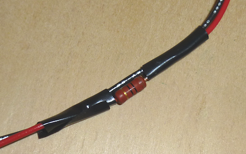
- Cut the red wire at some point along its length, perhaps 10"
or so from the LED end
- Strip about 1/2" of insulation from the two new ends of the wire
- Solder the new wire ends to the leads of a 10Ω, 2W resistor
- Wrap electrical tape or heat-shrink tubing around the exposed
resistor leads, to protect against accidental short-circuits with
other exposed metal parts in the cab. (Don't cover
the body of the resistor - that could make it overheat.)
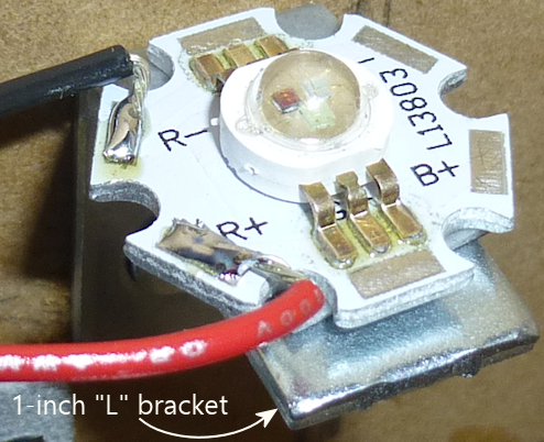
- Attach the LED to a 1" "L" bracket, using glue, paste, or
double-sided adhesive tape. I recommend a thermally conductive "heat
sink" tape, since that'll make the bracket into part of the heat sink
for the LED. Assuming you're using the "star" type, the aluminum star
base is already a good heat sink by itself, but it doesn't hurt to add
more cooling surface area given that we're going to leave this LED
running continuously.
Assemble the sensor
- Fit a lock ring onto the lens, and screw it all the way to the
top of (the wide part of the lens)
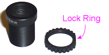
- Screw the lens into the lens mount
- Fit the sensor/lens spacer from the 3D-printed bracket over the sensor chip
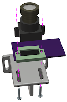
- Assemble the mounting bracket, circuit board (with spacer), and
lens/mount combo as shown below. Use M2 or #2 screws (whichever type
fits your lens mount) to fasten the parts together. Tighten the
screws just enough to hold the lens in position loosely - tight
enough that there's enough friction to hold its position, but still
loose enough that you can move it back and forth by hand. We'll need
to be able to fine-tune the alignment later when we install it in the
cab, so you want it to still be mobile at this point.

Install the sensor
The sensor has to be carefully positioned to satisfy three constraints:
- It has to be a certain distance from the plunger vertically, so
that the range of the plunger's travel will just fill the lens's
field of view
- It has to be at a certain point along the plunger's travel front-to-back,
so that the image can capture both ends of the plunger's travel range
- It has to be positioned side-to-side so that the lens points straight
at the plunger
The mounting bracket has slotted holes to give you a little wiggle
room to fine-tune the position and aim, but it's still important to
get the overall initial position right.
Warning! Be prepared for a little bit of trial and error to find the
ideal position. Given that we're using cheap no-brand lenses, I'm not
sure how consistent the optics will be from sample to sample. There
might be enough variation in the field of view that you might have to
move the bracket a little bit up or down from what worked for me.
Here's the positioning that worked for me. This is based on the
3D-printed mounting bracket plans earlier in this chapter. Obviously,
it's the position of the sensor that matters, not the position of the
bracket per se. But the sensor position relative to the bracket is
predictable, as long as we're all using the same bracket design, so
it's easier to work in terms of positioning the bracket.
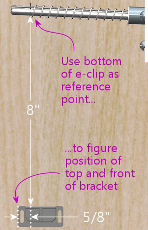
- Use the bottom of the plunger e-clip as the starting point
- Measure 8" straight down along the cabinet wall, and mark this
as the position of the top of the bracket
- From this point, measure 5/8" towards the rear of the cabinet,
and mark this as the left side of the bracket
- Now just fit the bracket so that its top left corner (as viewed in
the diagram above) fits the corner spot we just marked
Don't worry too much about getting the measurements exact. The
mounting bracket has slotted holes that will let you fine-tune the
final positioning based on what you see in the sensor viewer, plus I
tried to leave a little margin of error in these measurements so that
it'll still work if you're a little off. Besides, as I warned
earlier, your lens optics might be a little different from mine, so my
measurements might not be quite right for your setup anyway.
- Use the sensor bracket as a template to figure the screw hole
positions
- Try to center the screws in the slots so that you have
maximum room to adjust in both directions
- Drill 3/32" diameter pilot holes (about 1/4" deep) at the marked positions
- Install the bracket using two #6 x 1/2" wood screws
- Leave the screws a little loose for now so that you can adjust the
angle of the bracket when we test it in the image viewer below
Install the light source
The light source is the next (and final) piece to install. You should
already have wired the LED and fastened it to an "L" bracket for
mounting in the cab. Now you just need to find a convenient place
for it and install it.
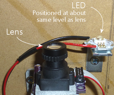
I recommend placing the light source close to the sensor, at about the
same level vertically as the lens. If you have room, I'd put it on
the side of the sensor closer to the front of the cab, but I think
it'll work fine on the other side, since these LEDs are very bright
and not very directional.
 Install the LED's "L" bracket using a #6 x 1/2" wood screw. I like
to drill a pilot hole (3/32" diameter, about 1/4" deep) first for this
type of screw.
Install the LED's "L" bracket using a #6 x 1/2" wood screw. I like
to drill a pilot hole (3/32" diameter, about 1/4" deep) first for this
type of screw.
Aim and focus
Now we have to align the sensor so that it gets a clear view of the
plunger through the lens, across the plunger's whole travel range.
There are two parts to this. The first is to position the sensor
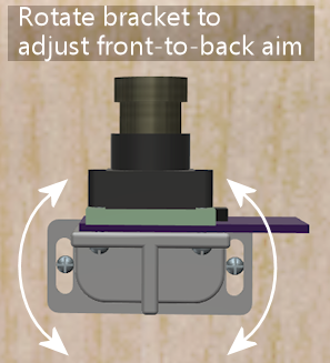
side-to-side so that it's aligned with the plunger axis. The second
is to adjust it front-to-back so that the plunger tip stays in view
across its whole travel range. For that second step, we should only
have adjust the angle of the bracket, so you shouldn't have to move
the screws fastening it to the wall - there should be enough range in
the slots that we can rotate the bracket to get the right alignment.
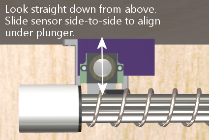
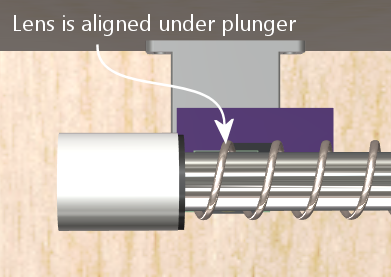
You can start the side-to-side alignment by visual inspection.
Looking straight down at the plunger, slide the sensor side-to-side
along the bracket until the lens looks to be centered under the
plunger.
 How precise do we have to be? The sensor's field of view side-to-side
is only one pixel wide, which translates to a fraction of a millimeter
along the plunger. The "target" that we're trying to image - the
white paper reflector - is about a centimeter wide. So we only have
to get our little one-pixel sliver to overlap that centimeter-wide
target. It's a broadside-of-the-barn situation.
Even so, aligning it by eye is just a first step, to get us into the
right neighborhood. To find the final position, we have to see what
the sensor sees. Luckily, the Config Tool lets us do just that.
How precise do we have to be? The sensor's field of view side-to-side
is only one pixel wide, which translates to a fraction of a millimeter
along the plunger. The "target" that we're trying to image - the
white paper reflector - is about a centimeter wide. So we only have
to get our little one-pixel sliver to overlap that centimeter-wide
target. It's a broadside-of-the-barn situation.
Even so, aligning it by eye is just a first step, to get us into the
right neighborhood. To find the final position, we have to see what
the sensor sees. Luckily, the Config Tool lets us do just that.
- If your dark backdrop isn't currently installed, put some kind of
temporary dark backdrop in place - a piece of dark paper that you can
lay on top of the cabinet above the plunger should be adequate.
- Turn on the LED light source
- Bring up the plunger viewer in the Config Tool (run the Config
Tool and click the "plunger" icon on the main page)
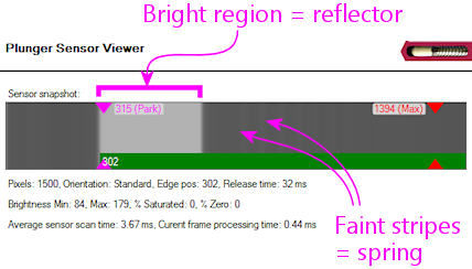
What we're looking for is a clear bright-colored region that fills
about a quarter of the field. That's the paper reflector we installed
at the tip of the plunger. You might also see some faint alternating
dark and light stripes; those are images of the spring and the plunger
shaft.
 If you don't see the bright region corresponding to the reflector, try
sliding the sensor side-to-side on the bracket. You might have to
hunt around a little bit before the plunger comes into view.
When you find the reflector, you should then fine-tune the position to
try to get it as close to the center-line as possible. That will give
you the clearest image, and it should also help better tolerate
vibration and small shifts in alignment. The plunger shaft usually
has a little bit of play that lets it move around by a couple of
millimeters in normal action, plus you have to expect all of the parts
to move around a little bit over time.
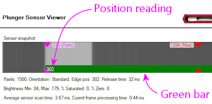
Front-to-back positioning: Now that you have the reflector
in view, the Pinscape firmware should be locking onto the plunger
position. You should see this as a green bar showing the current
position reading.
If you don't see the bright region corresponding to the reflector, try
sliding the sensor side-to-side on the bracket. You might have to
hunt around a little bit before the plunger comes into view.
When you find the reflector, you should then fine-tune the position to
try to get it as close to the center-line as possible. That will give
you the clearest image, and it should also help better tolerate
vibration and small shifts in alignment. The plunger shaft usually
has a little bit of play that lets it move around by a couple of
millimeters in normal action, plus you have to expect all of the parts
to move around a little bit over time.
Front-to-back positioning: Now that you have the reflector
in view, the Pinscape firmware should be locking onto the plunger
position. You should see this as a green bar showing the current
position reading.
 The goal now is to get the position reading (with the plunger at rest)
to be at about 300. Do this by twisting the mounting bracket
to re-aim the lens front-to-back. The slots in the mounting bracket
are there to allow a little rotation like this.
The goal now is to get the position reading (with the plunger at rest)
to be at about 300. Do this by twisting the mounting bracket
to re-aim the lens front-to-back. The slots in the mounting bracket
are there to allow a little rotation like this.
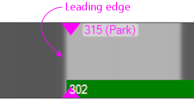
 Check the full travel range: Check that the leading edge of the
reflector stays in view across the whole travel range:
Check the full travel range: Check that the leading edge of the
reflector stays in view across the whole travel range:
- Pull the plunger all the way back
- Also push it forward, compressing the barrel spring as far as you
can
It's only important for the leading edge to stay in view, since
that's what the software looks for to find the position. It's fine if
part of the reflector goes past the end of the window when the plunger
is pulled all the way back.
If either end is out of view, try adjusting the mounting bracket
rotation again to get it into view.
Things to watch out for:
- What if you simply can't get both ends of the range in view, because
the field of view isn't wide enough for the travel range? This means
that the sensor is too close to the plunger. The positioning I
recommended is based on testing with my M12 lens with 16mm focal
length, but I'm not sure how consistent these cheap no-brand lenses
are from batch to batch. It's possible that the field of view won't
be quite the same with different lenses, which might mean you have to
adjust the distance between the sensor and the plunger. If the field
of view isn't wide enough, you'll have to increase the distance.
- What if the bright region starts disappearing halfway along the
travel range? This probably means that the sensor's pixel window
isn't close enough to parallel to the plunger, so that the plunger
moves "diagonally", relative to the sensor, as you pull it back. In
this case, you'll have to try to get the sensor lined up better with
the plunger axis, by rotating the sensor slightly on the mounting
bracket.
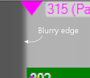
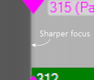
Focus: We're almost done. The next step is to focus the lens.
Use the viewer window to observe the leading edge, at the left side of
the view. Adjust the lens to get the sharpest edge you can.
 Finalize: Lock everything down in the calibrated position.
Tighten the screws that hold the sensor to the bracket and the screws
that hold the bracket to the cab wall. Set the focus lock ring, by
screwing it down the lens until it locks against the lens holder.
Keep an eye on the plunger viewer throughout, to make sure that you
don't knock things too far out of alignment while tightening any of
the fasteners. I always find that things move around at least a
little bit any time I adjust a screw, so do just a little bit at a
time, monitor the effects in the viewer, and re-adjust the lens
alignment as needed.
Calibrate: There's one last step, which is to run the
calibration procedure in the Config Tool. This lets the software
determine the resting position of the plunger on the sensor and
measure its range of motion, so that it can report the position in
terms that pinball simulators like Visual Pinball can understand. The
simulators need the numbers to be expressed on an abstract scale where
"zero" is the resting position, so the calibration procedure is needed
to figure the translation between the raw pixel positions on the
sensor and the abstract scale that the simulators use.
The calibration procedure can be accessed from the Config Tool's
plunger viewer screen. Simply click the Calibrate button and
follow the on-screen instructions.
Finalize: Lock everything down in the calibrated position.
Tighten the screws that hold the sensor to the bracket and the screws
that hold the bracket to the cab wall. Set the focus lock ring, by
screwing it down the lens until it locks against the lens holder.
Keep an eye on the plunger viewer throughout, to make sure that you
don't knock things too far out of alignment while tightening any of
the fasteners. I always find that things move around at least a
little bit any time I adjust a screw, so do just a little bit at a
time, monitor the effects in the viewer, and re-adjust the lens
alignment as needed.
Calibrate: There's one last step, which is to run the
calibration procedure in the Config Tool. This lets the software
determine the resting position of the plunger on the sensor and
measure its range of motion, so that it can report the position in
terms that pinball simulators like Visual Pinball can understand. The
simulators need the numbers to be expressed on an abstract scale where
"zero" is the resting position, so the calibration procedure is needed
to figure the translation between the raw pixel positions on the
sensor and the abstract scale that the simulators use.
The calibration procedure can be accessed from the Config Tool's
plunger viewer screen. Simply click the Calibrate button and
follow the on-screen instructions.
- Match the parts to the pads on the board using the "designator" - R1, C1, etc
- As you place the parts, press down on them gently with the tweezers to stick them to the paste
- Resistors aren't polarized, so it doesn't matter which direction they go
- Capacitor C1 isn't polarized, so its orientation doesn't matter
- Capacitor C2 is polarized, so its orientation does matter.
The part's plastic base has an asymmetrical shape that serves as the orientation
guide. Match the shape to the outline printed on the board.
- The transistor's (Q1) orientation should be obvious from the pad layout
- Make sure that the sensor chip is oriented correctly: the
white circle printed on the board in the corner of the corresponds
to the "index" mark - a dot - printed on the bottom
of the chip next to pin 1. Note that the index mark is printed
on the bottom of the chip, so you'll have to do a little spatial
reasoning to keep track of where it goes when you flip the chip over.
- The other IC chip (IC2) also needs to be oriented properly, in this case by matching the little half-moon notch on the chip to the notch printed on the circuit board outline
- Remove the board from the work surface and put it on something heat-safe
- Set the heat gun to low
- Point the gun at the board and hold it about an inch from the board, straight above
- Make small circles over the board to heat the board evenly
- Do this for about 60 seconds. This is the ramp-up phase - we're trying to heat the board gradually here so that there's no thermal shock.
- Set the gun to high, continuing to point it at the board and make small circles
- Watch the solder paste; in 30-60 seconds, it should start melting; it'll change from the dull gray paste color to bright silver
- Once all of the solder is melted, continue heating for about 10 or 20 seconds more to let the solder flow over the pins and pads
- Now gradually back the gun away from the board - two inches for a few seconds, three inches for a few seconds, etc. Keep going like this for about 30 seconds.
- Turn off the gun
- Let the board cool
You can skip the ribbon cable connector if you plan to use hook-up wire instead of a ribbon cable. I'd recommend the ribbon cable with this board, not only because it's easier (in my opinion), but because it makes a cleaner signal path for the high-speed data signals this sensor uses.
- Breakout board 3.3V to KL25Z P3V3 (pin 8 on J9)
- Breakout board GND to KL25Z GND (pin 12 or 14 on J9)
- Breakout board D0 to Kl25Z PTE21 (pin 3 on J10)
- Breakout board B0 to KL25Z PTB0 (pin 2 on J10)
- Breakout board E20 to KL25Z PTE20 (pin 1 on J10)
- Breakout board D5 to KL25Z PTE22 (pin 5 on J10)
Typical snapshot with the sensor working. The pixels appear with
a fairly uniform shade of gray. This particular snapshot has the
sensor in a shaded area, so it's not picking up much light.
With more ambient light, the pixels will be lighter gray or
closer to white, but should still look fairly uniform. If the
pixels look "noisy", with a lot of variation from one pixel to
the next and a lot of rapid fluctuation, there might be a problem
in the wiring or pin assignments.
