106. Plunger Setup (VL6180X Distance Sensor)
I should start by saying that I don't consider this to be a very good
option. I'm including it because it's easy to set up and fairly
cheap, so it might be appealing to some people on those grounds. It
also has the virtue of being a non-contact sensor, so it won't suffer
any wear and tear from use. But its accuracy and speed are too low
for me to recommend it. It's only accurate to about 1 centimeter,
which translates to chunky animation of the on-screen plunger (the
best available Pinscape plunger sensors are accurate to better than
1/100 of a centimeter). It's also comparatively slow, which makes it
less responsive than other options. With those warnings in mind...
The VL6180X is a distance measuring sensor that works by sending out
pulses of IR light aimed at a target, detecting the reflected pulses
with a photosensor, and measuring the round-trip travel time of each
pulse. It uses the travel time to determine the distance, using the
known speed of light in air.
To use this for a virtual pinball plunger sensor, the basic idea is
install the sensor at a fixed position just beyond the end of the
plunger, with the sensor pointing at the tip of the plunger. As you
pull back the plunger, the distance between the sensor and the plunger
increases. The sensor's distance measurement tells us the plunger's
current position.
VL6180X vs. VL53L0X
The VL53L0X is a newer chip from the same manufacturer with similar
distance measurement features. It's not an outright replacement for
the VL6180X, as it's not software-compatible and doesn't have exactly
the same features. Its main advantage over the older chip is that it
has a much higher maximum ranging distance, up to about 200cm vs only
10cm for the VL6180X. However, there's a tradeoff: it's considerably
slower than the VL6180X. The VL6180X completes a distance measurement
in about 13ms, whereas the VL53L0X requires at least 19ms, and is
happiest at about 35ms. In my testing, the newer chip doesn't have
any accuracy improvements over the old one.
Given the tradeoffs, I don't see any reason to use the VL53L0X over
the VL6180X for plunger sensing. The longer range of the newer chip
doesn't make any difference for us since we don't even need the full
range of the older chip, and the reduced speed is a negative. If the
newer chip's accuracy were noticeably better, that would make it more
of a contest, but both chips seem to have about the same (poor) accuracy.
Electronics
You can buy pre-assembled VL6180X circuit boards from several robotics
hobby companies. This is lucky for us, because the bare chips are
rather challenging to work with. The pre-fab boards make them easy to
use.
Here are three options:
All of these options are pretty much equivalent. They all provide
easy-to-solder terminals for all connections, and they all have the
necessary on-board voltage regulators and level shifters to interface
the VL6180X with the KL25Z. Any of these boards can be used directly
with the KL25Z hardware and Pinscape software; the only thing you
have to do is run a few wires between the KL25Z and the sensor board.
The instructions below are designed around the Pololu board. I chose
that one as the reference point because it's the cheapest and smallest
option. You can substitute one of the others if you prefer, but be
aware that you'll have to adapt the instructions below for any
differences in the board you choose. The other boards are all very
similar, so this shouldn't be difficult, but keep it mind as you build
the project.
Wiring the board
The breakout boards all come fully assembled, except for external wire
connections. The only thing we have to do is attach the wires between
the board and the Pinscape controller.
Your board might come with a set of pin headers that you can
optionally solder to the pads on the board. You can use these if you'd
like, but I'd actually recommend soldering wires directly to the pin
pads instead of using the pin headers. Using the pins creates a bit
of extra work, since you'll have to build an extra connector to plug
into the pins. I'd skip the pins and solder wires directly to the
board terminals, since you really shouldn't ever need to disconnect
the wires from the sensor board. We will use pluggable connectors at the
other end, where we plug into the Pinscape board, so you'll still
be able to easily unplug the whole assembly if you ever need to remove
it from the cabinet.
I recommend 24 AWG stranded wire for the connections, but the exact
gauge isn't important, as these wires carry extremely low power.
You'll need five wires, about three feet long each. Before cutting
the wires, check the length you'll need by measuring the distance the
wire will have to traverse to reach from your plunger housing to the
Pinscape unit (the KL25Z or main expansion board). Take into account
any extra length you need to route it around your PC motherboard or
other obstructions.
Strip about 1/4" of insulation from each end of each wire.
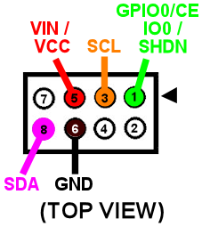
Solder one wire to each of the following terminals on the board:
- VIN (Adafruit and Pololu) or VCC (Sparkfun) (not VDD or 2.8V)
- GND
- SDA
- SCL
- GPIO0/CE (Pololu), SHDN (Adafruit), or IO0 (Sparkfun)
Note that your board will have some other terminals besides those listed
above. You can simply leave other terminals unwired.
Be careful about the "VIN" voltage input terminal! This one can
be a little confusing because some of the boards have two "V"
terminals. One is for the input voltage: this is the
one we want to connect. The other is for the output of the on-board
2.8V voltage regulator. We don't want to connect anything to
the 2.8V output. On the Adafruit board, the 2.8V output is plainly
labeled as "2v8", while it's more obscurely labeled on the Pololu
board as "VDD". In either case, just leave this terminal unconnected.
Expansion board wiring
For the expansion board connector, build a 4x2 crimp pin housing
(housing, pins).
First crimp a pin to the end of each wire (see Crimp Pins).
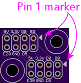
Insert the pins in the housing, following the diagram below for the pin placement.
It would be a good idea to put a mark of some kind on the housing in
the corner next to pin 1 - the pin marked with the arrow on the
diagram above. That will make it easier to remember which side
aligns with the "pin 1" arrow marker on the circuit board when
you plug in the connector.
Standalone KL25Z wiring
For the standalone KL25Z, I recommend using the plunger
sensor breakout board. Then you can just plug it into the breakout board.
- Build the expansion board connect as described above
- Build the ribbon cable connector exactly as described above, as though you were using the expansion boards
- Follow the instructions in Plunger Sensor Breakout Board to build the breakout board
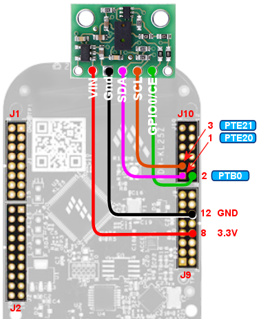
- Connect the following wires between the breakout board and the KL25Z:
- Breakout board 3.3V to KL25Z P3V3 (pin 8 on J9)
- Breakout board GND to KL25Z GND (pin 12 or 14 on J9)
- Breakout board B0 to KL25Z PTB0 (pin 2 on JP10)
- Breakout board E20 to KL25Z PTE20 (pin 1 on JP10)
- Breakout board D0 to KL25Z PTE21 (pin 3 on JP10) (Yes, the label on the breakout board is different in this case)
If you prefer to use your own ad hoc wiring, see "Plug it in" below for
the list of KL25Z GPIO connections.
Physical installation
I haven't come up with a reference design for the housing for this
sensor, so you'll have to come up with something on your own. The
basic idea is to mount the sensor at a fixed position in your
cabinet so that it faces the tip of the plunger head-on. The point
is to measure the distance between the sensor and the plunger.
There have been several commercial virtual pinball plunger kits
available over the years that were also based on IR proximity sensors,
so we can look to them as examples for how we might set this up. All
of those used a plastic tube surrounding the plunger, with the sensor
installed at the far end of the tube, facing the plunger tip. The
plastic tube serves dual purposes: it provides a place to mount the
sensor, and it shields the whole area from stray light that could
interfere with the sensor's readings. The VL6180X actually doesn't
actually need such shielding as much as the older sensors used in the
commercial kits do, since it has a "laser ping" design that's pretty
good at ignoring ambient light, but even so, it wouldn't hurt.
Choosing a material for the tube: This isn't as simple as it might
seem! Intuitively, it seems like any kind of opaque material would be
good. But the sensor uses infrared light (technically, 850 nm), and
many materials that look opaque to our eyes are actually transparent
to IR. The common 3D printer plastics PLA and ABS are both partially
transparent to IR, so it would somewhat defeat the purpose to use them
for a light shield. Black PETG is supposed to be nearly opaque to IR,
so it might be a better choice. It might also be a good idea to make
the inside surface texture of the tube or cover somewhat rough, to
minimize reflections. A smooth surface that readily reflects the
signal might be worse than no cover at all.
Choosing the sensor mounting position: Make sure that the sensor is
far enough away from the end of the plunger's range of motion that the
plunger won't ever hit the sensor. Remember that the plunger springs
forward about half an inch from its resting position, because the
barrel spring on the front can compress a bit. Leave a gap of at
least 1 centimeter (about half an inch) if possible.
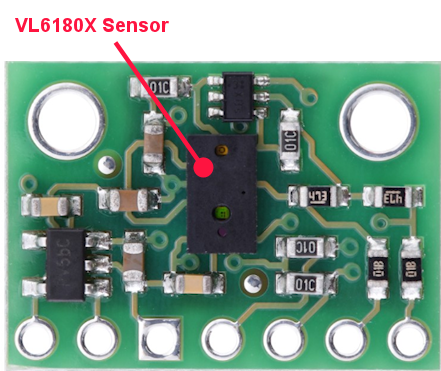
When you mount the board, be sure to mount it with the component
side facing the plunger.
Here's what the Pololu board looks like. The sensor is the little
black box in the middle with two small holes (one hole is the laser
emitter, the other is the photosensor). The sensor chip looks the
same on all of the boards, but the layout of the terminals and
the other parts varies slightly.
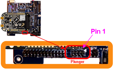
Plug it in
Expansion boards:
Once you've built the connector as shown above, simply plug it into the
plunger connector on the main expansion board. Make sure the plug orientation
is correct by match pin 1 in the housing (see the diagram)
with the pin 1 triangle printed on the expansion board.
Standalone KL25Z:
If you're using the plunger sensor breakout board (recommended), build the
expansion board connector as described above, and just plug it in to the
pin header on the breakout board. Be sure pin 1 on the plug (see the diagram)
to pin 1 on the board, which is marked with a little white triangle
printed next to the header.
If you prefer to use your own ad hoc wiring, connect the wires between
the board and the KL25Z as shown below.
| Sensor Board Pin | KL25Z Pin |
|---|---|
| 3.3V | P3V3 (JP9-8) |
| GND | GND (JP9-10) |
| SDA | PTE20 (JP10-1) |
| SCL | PTE21 (JP10-3) |
| GPIO0/CE | PTB0 (JP10-2) |
Note that the last pin, GPIO0/CE, has different names on some of the
boards: it might be labeled IO0 or SHDN. It's the same pin in any
case; the different board makers just chose to give it different
labels.
The illustration below shows the Pololu board. Be sure to adjust the
pin ordering if you're using a different board. Just match the labels
shown on the diagram to the labels printed on your board.
Note that the three GPIO ports listed above are only suggestions. If
you're already using the same ports for other functions, you can
assign the sensor inputs to other ports using the Config Tool. Any
free GPIO ports can be used with this sensor (it doesn't have any
special requirements for particular ports). The power and ground
wires aren't configurable, though, so connect those as shown.
Software setup
Once you have the sensor physically installed and plugged in, run the
Pinscape Config Tool on your PC. Go to the Settings page. (If you
have multiple Pinscape units installed, choose the Settings page for
the unit that's plugged into your new plunger sensor.)
Go to the Plunger Sensor section. Select VL6180X in the "sensor type"
popup.
(If the VL6180X option isn't available in the plunger sensor list,
you probably have an older version of the Config Tool. Updating to
the latest version should add the option.)
If you're using the expansion boards, the pin settings will be
set up automatically.
If you're using the standalone KL25Z, set the pin assignments for the
three pins (SDA, SCL, and GPIO0/CE) to match the pins you connected
on the KL25Z. The SDA and SCL pins should match the pins you
wired to the like-named terminals on the sensor board. The last one,
GPIO0/CE, goes by different names on the different boards: on the
sensor board, it will be labeled as GPIO0/CE, IO0, or SHDN, depending
on which type of board you have.
Save the new settings by clicking "Program KL25Z" at the bottom of the
window.
You should now test and calibrate the plunger. Return to the home
screen in the Config Tool and click the Plunger icon for the unit
with the sensor attached. This will let you look at the raw sensor
input. Move the plunger and make sure it seems to be tracking
properly.
If the sensor is working properly, click the Calibrate button in
the plunger viewer window to begin the calibration process, and
follow the on-screen instructions.
If the sensor doesn't seem to be working, go back to the Settings screen and
double-check the sensor pin assignments. Make sure that none of the pins
are marked with warning icons ( ).
Check each wire and make sure that it goes to the proper pin on
each end (KL25Z and sensor board). Check that each GPIO port
assignment on the settings page matches up with the physical
pin on the KL25Z and connects to the corresponding terminal
on the sensor board.
).
Check each wire and make sure that it goes to the proper pin on
each end (KL25Z and sensor board). Check that each GPIO port
assignment on the settings page matches up with the physical
pin on the KL25Z and connects to the corresponding terminal
on the sensor board.
).
Check each wire and make sure that it goes to the proper pin on
each end (KL25Z and sensor board). Check that each GPIO port
assignment on the settings page matches up with the physical
pin on the KL25Z and connects to the corresponding terminal
on the sensor board.
Jitter filtering
The VL6180X generates distance readings in millimeters, but it's
really only accurate to about a centimeter, so the millimeter numbers
it comes up with are pretty much just wild guesses. As a result, the
readings fluctuate quite a bit from one reading to the next, even when
the target is standing still. With a stationary object, you'll see
the readings jump around constantly within about 5mm of the true
distance, plus or minus. This is annoying and unrealistic during
virtual pinball play, because it makes the on-screen plunger dance
around nervously when the real plunger is standing still.
The Pinscape firmware offers a "jitter filter" to deal with this. The
jitter filter lets you set a range for ignoring random fluctuations. As long
as the random noise from the sensor stays within the range, the device
ignores the fluctuations and reports a stable, stationary plunger.
The on-screen plunger only moves when the sensor readings move outside
of the noise window.
To enable the jitter filter, run the Pinscape Config Tool and go to
the Plunger Viewer window. There's a setting in this window for the
jitter filter. To adjust it, start with the filter at zero, and
gradually increase it until the green bar showing the filtered reading
stops jumping around. Use the smallest value that gives you
acceptable results, because larger values will reduce the usable
precision during play.
Backwards operation
If the on-screen plunger moves backwards from the real plunger, you
can fix it in the software without reinstalling the sensor. Open the
Pinscape Config Tool. In the row for the controller, click the
Plunger icon. Check the box for "Reverse orientation". (If it's
already checked, un-check it.) This tells the software to reverse the
readings from the sensor, so that it acts like it was installed in the
opposite orientation.
