Appendix 12. Lock Miter I: The Plywood-Friendly Way
The original Williams pinball cabinets of the 1990s used a type of
corner join known as a lock miter. This join has mitered corners
(meaning the ends of the pieces that come together at a corner
are cut at 45°, so that the seam is exactly the corner, making
it practically invisible), plus an interlocking tongue-and-groove pattern on
the inside (that's the "lock" part). There are other good ways to make
the corner joins, but the lock miter is one of the best.
The corners are seamless, the joints are self-aligning and self-squaring,
and they have a lot of internal surface area for strong glue adhesion.
Lock miter corners are also make assembly really easy, since the
corners snap together like jigsaw puzzle pieces.
There are (at least) two ways to make a lock miter join. The first
method, which we'll cover in this chapter, involves making a sequence
of cuts (six steps in all) with a 1/4" straight router bit and a table
saw. I'm covering this method first because it works very well with
plywood, which is what most pin cabs are made of. This method might
look a little intimidating at first, because of the number of steps
involved, but it's actually not that bad. Most of the steps are
pretty simple, and they mostly use natural alignment points that don't
require any arithmetic or ruler measurements.
The second method involves a special router bit that cuts the entire
tongue-and-groove pattern all at once. That's covered in the next
chapter, Lock Miter II: The Special Router Bit Way. That method probably looks easier
at first glance, since the bit does all of the work for you. But
these bits are notoriously difficult to set up properly. There is a
reliable setup procedure, but the time and effort involved in that
ends up making the overall degree of difficulty similar to the more
manual "plywood friendly" method. The real drawback of the
special-router-bit approach is that the tongue-and-groove structures
that the router bits cut are too fine for most plywood, so you
lose a lot of the strength that the join is supposed to provide.
If you're new to woodworking, both methods are probably going to look
like "advanced" procedures that should only be tackled by grizzled
veterans with lavishly equipped wood shops. But don't give up yet!
I'm a woodworking newbie myself, and I've found that both techniques
are doable and can yield great results, even if you're new to this.
I've tried to reduce both methods to straightforward recipes that you
can follow without any special woodworking expertise and with
a modest set of tools.
Example of the manual method
Here are some photos of a sample corner built with the manual
method, to give you a better idea of what it looks like.
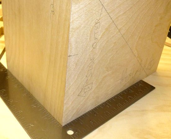
Dry fit of a test corner built using the manual lock miter method.
This is just a couple of scrap pieces that I ran through the process
in this chapter as a beta test. It took about an hour of work;
most of that was spent on the "sneaking up" phase
for the 45° angled cuts. It came out just about perfect -
the two pieces fit together nicely, and the corner is razor-sharp.
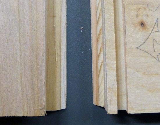
A closeup of the grooves, with the front/back piece on the
left and the side piece on the right.
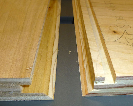
Another view of the grooves. The thing I like about this
version of the lock miter (the "manual" approach) is that
the tongue-and-groove structure comes out so clean and sturdy
when rendered in plywood, thanks to the relatively large features.
Compare this to the similar pictures of the special router
bit results in Lock Miter II: The Special Router Bit Way).
Pros and cons of the two methods
If you're considering using lock miter corners for your pin cab
project, I'd suggest reading through both methods, so that you can
judge for yourself which one you feel more comfortable with. Here's
a quick summary of what I think are the high and low points of
each approach.
| Router Bit Method | Manual Method |
|---|---|
| Special router bit required ($25-$100+) | Needs only a 1/4" straight router bit (and can be done with just a table saw, no router needed) |
| No table saw required | Requires a table saw |
| Not great for plywood; tongue-and-groove features have poor structural integrity due to small size | Excellent results with plywood, makes a super strong joint |
| Only needs one routing pass over each edge | Six cutting steps required |
| Bit setup is notoriously difficult (but doable if you follow the right procedure) | Fairly straightforward setup for each cut (but there are still six of them) |
I've tried both approaches, and I've found that - surprisingly - the
manual method isn't really any harder or more time consuming than the
router bit method. It might even be a little easier. You'd think
that the special router bits would make things a whole lot easier,
given that they cut the entire pattern in one pass over each edge, but
the complex setup procedure makes up for it. The manual method
involves multiple cuts for each corner, but each one is fairly quick
and easy to set up, and the recipe is pretty reliable at getting all
of the cuts to line up accurately with one another.
Given that neither method has a clear advantage in terms of difficulty
level, my feeling is that the manual method has an edge for a pin cab
project, simply because of its better performance with plywood. The
main obstacle with the manual method for many people will probably be
that it requires a table saw. If you don't have a table saw and you
don't want to buy or rent one, the special-router-bit method is a good
fallback; even though it's not ideal for plywood, it is workable
with at least some plywood.
How the lock miter works
The lock miter is an elaboration of the plain miter join, which is
a simple join where you cut the ends of the two pieces meeting at a corner
at a 45° angle:
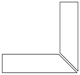
The plain miter gives you a nice clean corner without a visible seam,
but it doesn't make a very strong glue joint, and it takes some skill
to execute it well. For one thing, you have to get the two cuts
exactly at 45°, or the corner won't be square. The way the
two pieces meet means that any error in the cut angle of each piece is
doubled in the assembled corner. If you're off by 1° on the cut
angle, the corner will be out of square by 2°. The other thing
that's difficult with a plain miter cut is getting the two pieces to
align correctly during assembly. You have to get the corner aligned
across its whole length, and then keep it there while the glue dries.
There are corner clamp systems that help with this, but it still takes
some skill.
The lock miter improves on this by keeping the 45° angle at the
outside corner and adding an interlocking tongue and groove. There
are different ways to make the interlocking tabs. The special lock
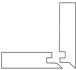
miter router bits produce a pattern that looks roughly like this:
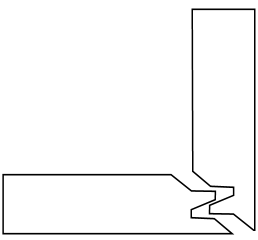
The manual method presented in this section produces this pattern:
The common features are the 45° angled cut at the outside corner,
and the interlocking tongue and groove. Like the plain miter, the
45° angle at the outside makes the corner seamless. The addition
of the locking tabs makes the assembly step almost effortless, since
the pieces can only fit together at exactly the right alignment.
And the extra surface area of the tabs forms a
strong glue joint. This join is also a little more forgiving of
imperfect 45° angles at the corner, since the locking tabs will
still keep the corner aligned and square.
You probably noticed that the router bit method and the manual method
have slightly different shapes for the interlocking tabs. The
differences aren't completely arbitrary. The key difference is that
the tongue-and-groove structures in the manual method are coarser.
That's what makes the manual method perform better with plywood. The
lock miter router bits are forced to use smaller features because
their cutting pattern has to form a mirror image. That's how they
work their magic trick of cutting both sides of a corner join with the
same bit. Every feature has to appear twice, once on each side of the
"mirror", so every feature has to be half-sized. The small
projections are problematic with plywood, in that the glued plies tend
to fall apart when cut so finely. The manual method doesn't have to
be symmetrical, since we make each cut individually. That allows for
larger features, which hold up better with plywood.
Equipment needed for the manual method
1/4" straight router bit: Just to be clear, we're talking about
a bit with a 1/4" cutting diameter (as opposed the shank size - for
that, simply match the shank size your router uses).
Router and router table: If you already have a hand router, you
can buy an inexpensive bench-top router table and use it with your
hand router. Most of the the bench-top tables are compatible with
many brands of routers, so you can generally mix and match tables and
routers. I use a bench-top table from Skil with a Ryobi fixed-base
hand router. The table isn't a high-end piece of precision equipment,
but it works for the pin cab joinery I've attempted.
Router table fence micro-adjuster: Optional but really helpful.
Provides a way to adjust the fence position in tiny fractions of an
inch, to help get the alignment perfect. This is something you can
make yourself as a simple DIY project described later in this chapter.
Table saw: For the 45° angled miter cuts.
1/4" MDF scraps: For use as alignment aids. You just need a
couple of scrap pieces, roughly 6"x6" and 2"x6". 1/4" plywood or
hard-board will also work.
Auxiliary fence for your table saw: A piece of 3/4" MDF or
plywood, cut to about the same size as your table saw's fence.
Doing it all with a table saw
You can create a lock miter using just a table saw, no router
required. You need a 1/4" dado stack in place of the 1/4" router
bit used in my procedure.
The steps in my procedure are tailored to the router table, so you
might want to look for a recipe that's specific to the table saw -
there are some equally complete table-saw versions out there. Search
the Web and/or Youtube for lock miter with table saw.
Or you could just adapt my recipe, if you don't mind puzzling out how
to translate the router fence alignment steps to the table saw. The
alignment points for the cuts are all the same relative to the boards,
so it doesn't take much translation. The main thing to watch out
for is that you'll need an auxiliary fence for a couple of steps,
since the saw blade will otherwise be too close to the main fence.
Do a practice run
This is a complex enough procedure that I felt the need to do a couple
of practice runs on scrap material before I tried it for a real
project. You might not need to, but I found it helpful as a
confidence booster, to make sure I understood all of the steps.
The other nice thing about a practice run is that it helped me
fine-tune my sense of the various alignment points. The procedure is
designed to make the alignment points easy to judge, but even so,
there's always a little wiggle room when trying to get two things to
line up. If anything comes out a little off in the test run, you can
use that as a guide to compensate the next time through.
Preparation
Get all of the panels ready: Wait until all of your panels are
cut to final sizes before starting the lock miter procedure. You
should do all of the lock miter routing across all panels at the
same time, so that you only have to do the setup part of each step
once.
I'd do the lock miter cutting on all panels before routing
other features (e.g., floor dados), drilling holes (flipper buttons,
say), and cutting openings (like the coin door cutout). The panels
are easier to handle whole.
Include a scrap "side" and "front" piece for testing every cut.
Reserve a small scrap piece of plywood for each, designating one as
"side" and one as "front". Make each cut on the corresponding scrap
piece first as a sanity check that you're set up correctly. This is
especially helpful in the steps where you have to "sneak up" on the
final alignments with a series of test cuts. The idea with "sneaking
up" is that you start with a cut that's intentionally shy of the real
cut line, then you check how close you got, and then gradually re-cut
closer and closer until you get exactly to the right spot. I
sometimes make the mistake of overshooting the final cut line because
I wasn't gradual enough in the re-do cuts. It's nice to know that
you're only ruining a piece of scrap if that happens.
Pre-mark all panels. The lock miter we're doing involves two
different cutting patterns, one for the side panels, and a
different one for the front/back panels. It's crucially important
that you cut the right pattern in each panel. To avoid switching
things around in the heat of battle, mark each piece conspicuously
before you start, to indicate whether it's a SIDE or
FRONT/BACK piece. I also like to mark the INSIDE and
OUTSIDE face of each piece so that I don't have to think about
that later. The inside/outside orientation matters for every cut. I
make all of these markings right along each edge where the lock miter
pattern goes, just beyond the cutting area (about 3/4" from the edge),
to help make sure I'm cutting the correct edge. I don't want to have
to think too much while the router is running - less chance of
screwing something up.
Install a 1/4" straight bit in your router. This bit will
be used for all routing throughout the procedure.
Set up an auxiliary fence for your table saw. Simply cut a
piece of 3/4" MDF or plywood to roughly the same size as your saw's
fence, and attach it to the blade side of the fence with clamps, with
the bottom of the aux fence about 3/8" above the table top.
A few tips, tricks, and precautions
Always unplug the router before adjusting the bit height or
fence position.
Make multiple router passes for grooves deeper than 1/4".
Router bits work best doing a little at a time. For deep grooves,
start with a first pass at 1/4" deep, then repeat at 1/2" deep, and so
on until reaching the target depth. Don't move the fence between
passes - only change the bit height.
Take a close look at your router bit and notice how it's not
perfectly round - it probably has a slightly oval shape, with cutting
edges that stick out slightly. When you're aligning something with
the outside of the bit, you want to make sure you're using the widest
part of the cutting edge as the reference point, since the bit will
remove material out to the widest point.
Table a close look at your table saw blade and notice how the
teeth are a bit wider than the main disk. When aligning an edge with
the saw blade, you always want to align with the widest point of the
teeth, since the cut line will go out that far.
To avoid tear-out at the end of each cut where the router bit
exits the board, try putting some masking tape along the trailing
edge. If that doesn't work, use a scrap piece of the same 3/4"
material, and keep it pressed up against the trailing edge as you push
the end of the real work piece past the bit.
Cutting steps
The cutting procedure works by aligning each cut with a previous cut.
I've tried to provide an easy method to hit each reference point
without any guesswork. At each step, I'll explain the goal we're
trying to accomplish, and then give you the method I use to accomplish
it. Each step also starts with a schematic diagram showing the
goal, but don't worry about trying to puzzle out the setup from
the schematic - it's just there so you can see what the step's
cut will look like and how it fits into the overall pattern.
Several of the steps have a setup procedure and a test
procedure. The test procedure in each step is optional, so feel free
to skip that part if it feels too tedious. The setup steps alone are
pretty reliable. But I find that the extra test-and-adjust steps
help me get the alignments closer to perfect.
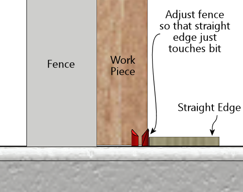
Step 1: Inner groove on the side pieces. This groove
has to align with the inside face of the front/back piece, so we'll
use the thickness of a sample work piece as our alignment guide for
the fence. The bit height is simply 1/4".
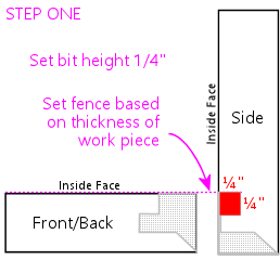
Set the bit height to 1/4" above the table, using a ruler or other
measuring tool of your choice. (For better precision, use good set
of calibrated setup bars - search for router setup bars on
Amazon.)
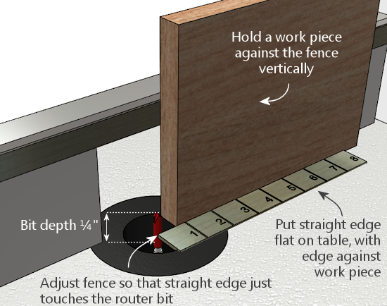
To position the fence, place one of the work pieces against the fence
vertically. (It doesn't matter which piece - all we care
about here is the thickness, which is the same for all work pieces.)
Make sure to keep it tight against the fence. Place a straight edge
flat on the table along the edge of the work piece, with one end
extending out so that it's alongside the bit. Adjust the fence so
that the bit just barely touches the straight edge. Rotate the bit
back and forth to make sure that you're testing it at the widest
point.
This is a good time to deploy the
fence micro-adjuster, to
help get the alignment perfect.
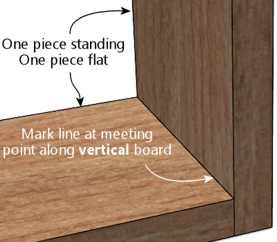
The alignment on this step is pretty important, so if you want to be
extra-careful, you can run a quick test. Take two scrap pieces (from
the same plywood as the real pieces, of course), lay one flat, and
stand the other one up alongside it as shown below. Mark a line on
the vertical piece using the horizontal piece as a straight edge.
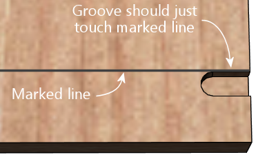
Route just an inch or so of the marked piece (line facing down and
towards the fence), and check that the groove is exactly up against
the line. It shouldn't cross the line or cut into the line - it
should leave the line intact and just touch it with exactly zero
clearance. If it's a little off one way or the other, use the
micro-adjuster to compensate, and test it again.
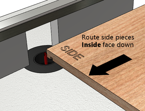
Once you're set up, it's time to the do the actual routing
for this step. Route each SIDE piece, with the INSIDE FACE down.
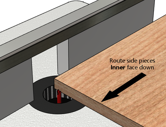
Remember to route both ends of each side piece, for the joins
at the front and back.
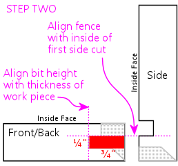
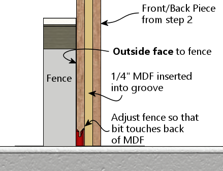
Step 2: Cut the center groove in the front/back pieces. The
groove's depth has to equal the thickness of the work piece, so we'll
set the bit height based on a sample work piece's thickness. The
inside of the groove has to align with the outside of the side groove
from step 1, so we'll set the fence position using the actual groove
in one of the side pieces as a reference point.
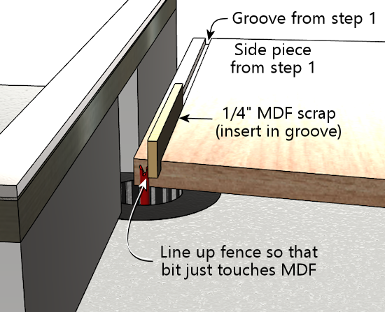
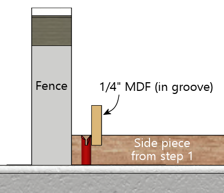
Grab one of the side pieces you just cut and fit a piece of 1/4" MDF
scrap into the groove as shown below. Place it on the router table
with the edge against the fence. Set the fence so that the bit just
touches the MDF.
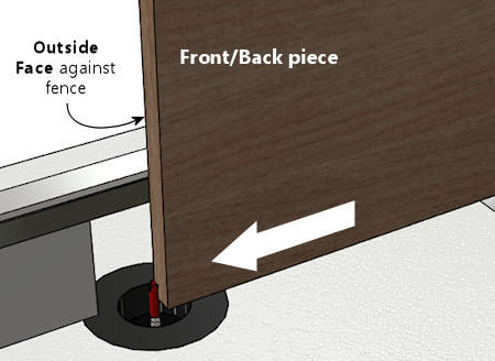
Here's how we're going to do the routing for this step. Route the
FRONT and BACK pieces vertically against the router
fence, with the OUTSIDE FACE to the fence. But we're not
quite ready yet - we might want to check the alignment first, and we
still need to set the bit height.
If you want to check the alignment to make sure it's right, there's a
quick test that you can do before proceeding. Set the bit height to
about 1/4" above the table, grab a scrap testing piece, and route it
as shown above. This is just a test cut, so you only need to go an
inch or two. Now measure the width of the "tongue" on the
inside face, as illustrated below. I find digital calipers are
the easiest way to get a precise reading here. The thickness should
be just a hair under 1/4" (6.35mm) thick. Something like 6.2mm to
6.3mm is perfect. This tongue slots into the 1/4" groove from step 1
when you assemble the corner, so it can't be any thicker than 1/4", or
it won't fit the groove. It's best if it's just the slightest bit
thinner than 1/4", so that it fits easily but snugly. A looser fit
isn't a disaster, but it won't be as strong when assembled, and it
might not self-align as perfectly. If you're using the fence
micro-adjustor, you can use the measurement to figure out how many
turns of the screw are needed to get it exactly to a target of, say,
6.2mm. In any case, if you make an adjustment, I'd repeat the test
(in my case, because I'm 50% likely to go the wrong direction, even if
I'm looking straight at these instructions).
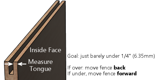
| Measured Width | Make This Adjustment |
|---|---|
| Over 1/4" | Move fence back (away from bit) |
| Under 1/4" | Move fence forward (towards bit) |
Now we're ready to set the bit height. This is a deep enough groove
that it's best to route it in multiple passes, so that we don't try to
force the router bit through too much wood at one time.
- First pass: bit height set to roughly 1/4" above the table
- Second pass: bit height set to roughly 1/2" above the table
- Final pass: calibrate to the work piece thickness
For the final pass, calibrate the bit height to match the thickness of
the work pieces by placing a work piece flat on the table alongside
the router bit. Adjust the bit height so that it matches the plywood
thickness (or just a hair beyond). A straight edge on top of the
work piece can help get it perfectly aligned.
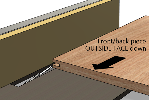
For each pass, route as shown in the illustration we saw earlier:
route the FRONT and BACK pieces vertically against
the router fence, with the OUTSIDE FACE to the fence.
Here's the illustration again:
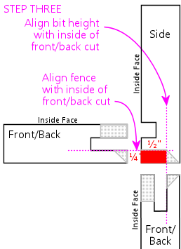
Step 3: Outer groove on the side pieces. This step finishes
the "tongue" on the side pieces. The fence position for this cut has
to align with the outer side of the front/back groove from step 2, so
we'll use a front/back piece from the previous step as a reference
point. The bit height has to align to the leftover portion outside
the groove from step 2, so we'll also use a front/back piece as a
reference for that.
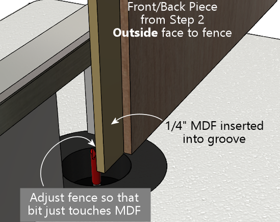
Take a front/back piece from step 2, and insert a scrap piece of 1/4"
MDF into the groove. Stand this vertically against the router fence
with the OUTSIDE face of the front/back piece against the
fence. Place it so that the MDF extends just past the bit.
Adjust the fence so that the router bit just touches the back
of the MDF.
This is another deep cut that's best done in two passes - first at
1/4" deep, then at full depth. So set the bit height to 1/4"
above the table for the first pass, route all of your side
pieces, and then set the final bit height as described below.
Here's how we're going to do the routing: SIDE pieces, flat
against the router table, INSIDE face down.
Before routing your actual side pieces, though, you can do a quick
test to check the fence alignment. You'll need the scrap "side" piece
from step 1, that already has the 1/4" wide by 1/4" deep groove set in
1/2" from the edge. Do the test on that piece. Route it as shown
above, but you only need to go for an inch or two for this test.
Now measure the width of the "tongue" between the two grooves:
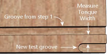
It should measure just under 1/4" (6.35mm). This part has to fit
into a 1/4" groove, so if it's more than 1/4" wide, it won't fit.
You don't it to be too loose, either, so the ideal is something
just under 1/4", perhaps 6.2mm to 6.3mm. If it's too wide, move
the fence back (away from the bit); if it's too narrow, move
the fence forward (towards the bit).
| Measured Width | Make This Adjustment |
|---|---|
| Over 1/4" | Move fence back (away from bit) |
| Under 1/4" | Move fence forward (towards bit) |
Once you're satisfied with the fence alignment, route all of the side
pieces as shown above, keeping the bit height set at 1/4" above the
table. Once done, you'll need to make one more pass over all of the
pieces at the final bit height.
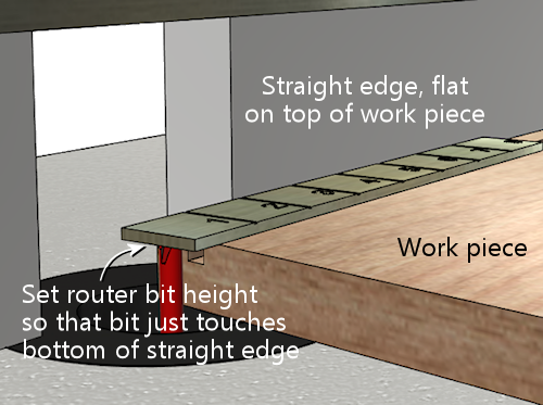
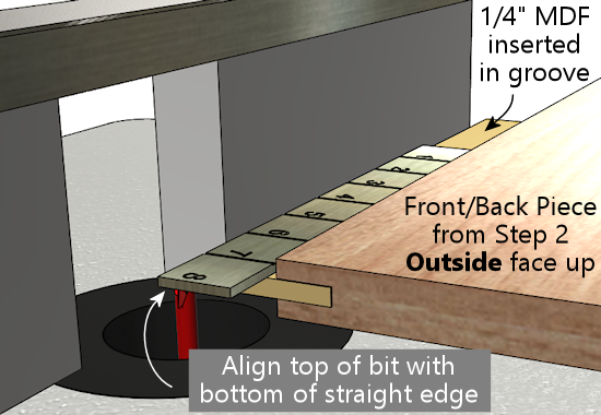
To set the final bit height, use a front/back piece with a piece of
1/4" MDF inserted into the groove. Put the whole thing flat onto the
router table as shown below, with the OUTSIDE FACE facing up.
Put a straight edge on top of the MDF so that it extends out over the
bit. Adjust the bit height so that the top of the bit just touches
the bottom of the straight edge.
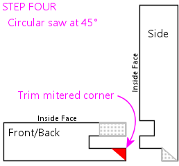
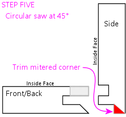
Step 4: Cut the 45° miter on the front pieces.
This step (and the rest of the steps) are on the table saw.
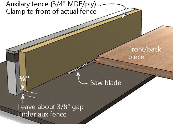
First, set up an auxiliary fence on your table saw. This is just a
piece of 3/4" MDF or plywood, cut to about the size of the fence, and
clamped to the front of the fence. Leave a gap of about 3/8" between
the bottom of the auxiliary fence and the table top, to make room for
the blade to extend 1/4" above the table.
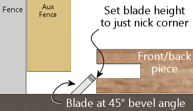
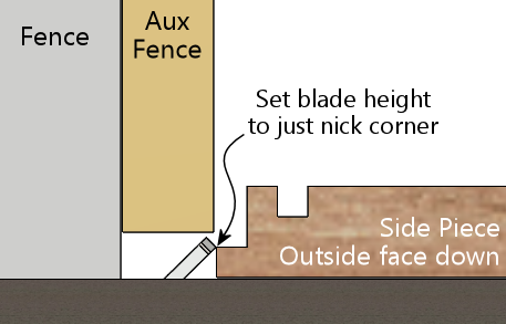
Set the saw blade to 45°. Adjust the height so that the
blade just nicks the corner of the tongue in a front/back piece,
as illustrated below.
This cut needs to be precise, and I haven't found an easy trick like
in previous steps to align it with another cut. The best approach I
can come up with is to "sneak up" on the final cutting position with a
series of test cuts. The good news is that you only have to do a
series of test cuts for one piece. Once that one piece looks perfect,
just run the rest of the front/back pieces through the saw with the
identical fence position, and they should all come out equally perfect.
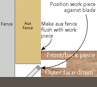
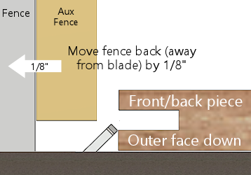
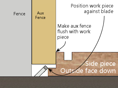
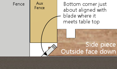
Start by positioning the fence to remove no material at all, by
pushing the work piece right up against the blade, and making the aux
fence flush with the work piece:
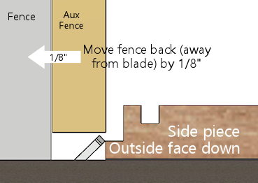
Now move fence back (away from the blade) by about 1/8".
When you move the work piece back behind the blade and push it
up against the fence, the bottom corner of the work piece should
now just about line up with the saw blade:
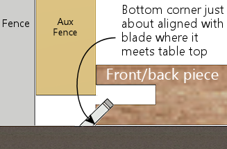
Double-check by eye that the blade is aligned as shown. Remember,
it's best to remove too little material at this point than too
much, since we can adjust things and take off a little more if we have
to. That's why we only moved the fence 1/8", even though the ultimate
target is closer to 1/4". If it looks like the blade is already going
to hit the bottom corner, move the fence a little further towards the
blade to open up a small gap.
Do a test cut, with the front/back piece OUTSIDE FACE down.
Tip: after each fence adjustment (including the first one), initially
only run the first few inches of the board through the saw, and
inspect the result to make sure the fence isn't already too back. If
the fence is too far back, you'll be cutting material off the outside
face of the outside edge, which you don't want to do. When this
happens, you'll see a little indent along the outside edge where
material was cut off. The goal is to get the 45° cut exactly
up to the outside edge of the outer face without actually cutting
any material off the outer face. Making a partial cut lets you see
immediately if you've gone too far, since the outside edge will no
longer be a straight line. You can't undo this, which is why I like
to include a scrap piece in every batch for these first cuts while
adjusting the fence.
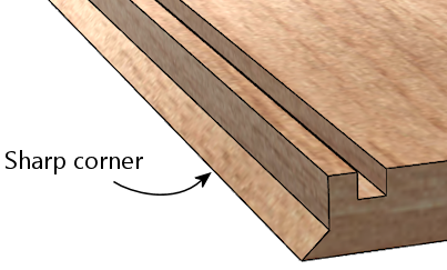
When it's exactly right, you should have a sharp outside corner.
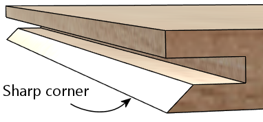
If the corner is still a little squared, you just need to adjust
the fence back slightly (away from the blade) and try again.
Make small changes to ensure you don't overshoot. Repeat
until the corner is sharp.
You can now run all of the remaining front/back pieces through.
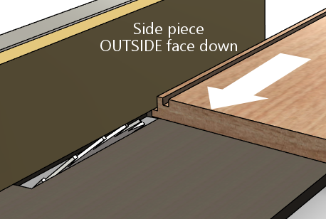
Step 5: Cut the 45° miter on the side pieces. This is
essentially the same as step 5, just with a different blade position
to match the side pieces this time.
You should be able to keep the same blade height from the previous
step, but check it with a side piece to confirm.
Adjust the fence position using the same drill as last time. Start by
pushing the work piece up against the blade, and making the fence
flush with the work piece:
Now back the fence away from the blade by about 1/8".
Move the work piece behind the blade and flush with the fence, and
verify that the blade isn't quite going to cut hit the bottom corner.
As before, it's better to cut too little at this point, since we can
re-cut a little more if necessary.
Do a test cut, with the side piece OUTSIDE FACE down.
As before, we're looking for a nice sharp corner.
If the corner is still a little squared, adjust the fence back
slightly (away from the blade) and try again. Make small
changes to avoid overshooting. Repeat until the corner is
sharp.
You can now run all of the remaining side pieces through.
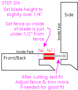
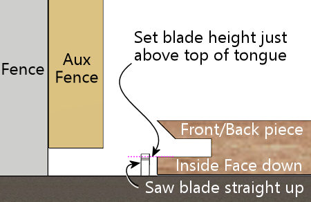
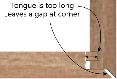
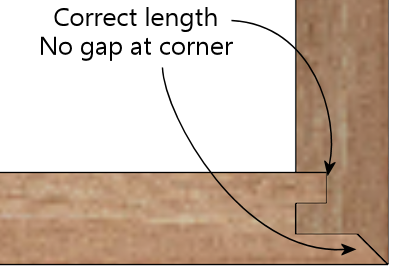
Step 6: Trim the tongue on the inside of the front/back pieces
so that it fits into the side slot from step 1.
I do this step last because it's another "sneak up" cut, and doing
it last lets us test to see if we trimmed enough off by doing an
actual test fit. That's the best test for exact alignment.
We'll use the table saw for this cut. Set the blade so that it's
straight up. Position a front/back piece on the table next
to the blade, inside face down. Adjust the blade height so
that it's just above the top of the tongue - about 1/4".
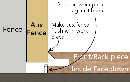
Put the work piece flush against the saw blade, and move the fence
so that it's flush with the work piece.
Now back off the fence, away from the blade, by about 3/8".
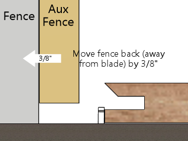
Since we have to "sneak up" on the final fence position with test
cuts, just do one edge of one front/back piece at first. We'll test
the fit and adjust as needed before running the other pieces.
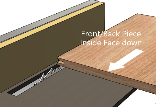
Run a FRONT/BACK piece through the saw, INSIDE FACE
down.
Test the fit against a side piece. The two pieces should fit together
at the outside corner without any gaps. If the tongue in the
front/back piece is jutting out and preventing the pieces from fitting
together, we need to trim it back a little more. Back the fence away
from the blade - just slightly - and do another test cut. Repeat
until it's a good fit.
Once you have a good fit with one piece, finish the remaining
FRONT/BACK pieces.
That's it - you're done! The corners should all fit together tightly.
If any of them are so tight that you have to force them together, try
manually sanding the sticking points.
Router fence micro-adjuster
Table saws usually come with rack-and-pinion fences that you can
adjust fairly precisely by turning a knob. Router tables, in
contrast, usually have much simpler fences, without any adjustment
mechanism at all. The fence usually just slides freely on a couple of
parallel tracks. You move it by hand to where you want it, then
tighten some knobs that hold it in place.
That's not a very precise way of positioning the fence, but it's good
enough for most applications. There are tasks where you can really
benefit from more precise positioning, though. Lock mitering is one
of them.
There's a solution, and it doesn't even require spending a fortune on
a super-deluxe router table. You can make a really simple
micro-adjuster for your existing router table fence. You don't have
to make any permanent modifications to the router table, and you can
build the micro-adjuster out of scrap wood and hardware you probably
have lying around. Here's the one I built:
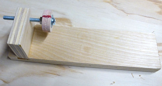
The wood is all 3/4" plywood, and the two pieces are simply glued
together at a 90° angle. (I routed a shallow 3/4"-wide dado
that the vertical piece slots into, which makes the glue joint
nearly unbreakable.) The screw is a 3" long, 1/4"-20 machine
screw. In the vertical plywood piece, I drilled a hole slightly
smaller than 1/4", and then worked the screw in so that it cut its own
threads into the wood.
I added a DIY knob, in the form of a "donut hole" cut out of 3/4"
plywood using a 1" hole saw. (There's a KEPS lock nut on the inside
to keep it in place.) I drew a big red mark so that I could easily
gauge full turns, half turns, quarter turns, etc. Alternatively, you
can buy a plastic knob at Home Depot or Amazon, or skip the knob
entirely and make adjustments with a screwdriver.
The micro-adjuster is simple to use. First, set up your fence as
close as you can get "by hand" to where you want it. Second,
tighten the knob-screw on one side to pin the fence down on that end.
Third, position the micro-adjuster behind the fence on the
other side (the un-pinned side), with the screw just touching
the back of the fence. Clamp the adjuster to the router table so that
it stays put at this position. You can now tighten the fence knob on
this side to fix the fence position here.
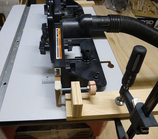
The micro-adjuster as deployed, sitting behind the fence on my router table.
It's simply clamped onto the table with an F-clamp.
My fence is MDF, so I masking-taped a penny to the back where the screw
contacts the fence, to make a harder contact point and prevent
the screw from making a divot in the MDF. Note that I also
clamped a small wood block behind the fence on the opposite
side to set a hard stop, to ensure that the fence can't slip back even slightly on that side. The fence
already has a knob that locks it down on each side, but I wanted to ensure
that there's absolutely no slippage when we micro-adjust the micro-adjuster side.
Now you can make tiny, precise adjustments to the fence position.
When you need to move the fence by a tiny amount, loosen the fence
knob on the micro-adjuster side only, and turn the screw in the
appropriate direction to move the fence forward or back. When moving
it back, you'll have to push the fence against the screw, since the
screw won't pull it back on its own, but the adjustment should
nonetheless stay very precise as long as you keep the fence pressed
against the screw.
If you're using a 1/4"-20 screw like I am, each full 360° turn of the screw
corresponds to 1/20 of an inch change in the fence position. (That's
the "-20" in 1/4"-20 - it means that the screw has 20 threads per
inch.) With a knob, it's easy to gauge a quarter turn, which
corresponds to 1/80 of an inch, or even an eighth turn for 1/160".
What's more, that's the distance the
screw moves. The thing that matters is how far the center of
the fence moves, since that's where the bit is. The center of the
fence only moves half as far as the screw, since the screw is at one
end and the other end is kept fixed in place. So an eighth turn on
the knob equals 1/320" of travel at the center of the fence. That's
plenty of precision for anything I've ever attempted.
You might wonder how we keep the fence "square" if we're only moving
it at one end. Moving just one end obviously will cause the fence to
angle slightly on each adjustment. If this were a table saw, that
would be a huge problem. But it's okay with a router table! The
difference is that router bits are round, so there's really nothing to
be "square" to. (Okay, technically, table saw blades are also round,
but a saw blade defines a plane that the fence must be parallel to.
There's no equivalent parallel plane for a router bit, so it doesn't
matter how the fence is angled.)
