65. Addressable Light Strips
Addressable or "smart" light strips are similar to the basic light
strips most cab builders use for undercab
lighting, but with the added feature that each LED on a smart
strip can be set to a different color. That's what "addressable"
means: each LED can be addressed - commanded - individually.
In pin cabs, these can be used in a variety of ways, such as:
- A strip of lights down the entire length of each side of the playfield TV, usually mounted on the side wall of the cabinet just above the TV. These can show chaser lights that follow the ball at certain times (such as when launching from the plunger), and can also show flashes of light situated near playfield flasher lights on the TV, to reinforce the video rendition of the flasher with a brighter nearby LED flash. (See Flashers and Strobes.)
- One strip or several rows of strips across the width of the back edge of the playfield TV. This can display more ball chaser light effects, and can also take the place of a dedicated flasher panel (see Flashers and Strobes). In matrix form (multiple rows of strips), it can also serve as a sort of supplemental DMD, to display additional dot animation effects during game play.
- A strip or several rows of strips mounted near the top of the backbox. This can simulate "beacon" devices (see Beacons).
- Addressables can also be used to illuminate the flipper and MagnaSave buttons (see Button Lamps). This function can also be performed (more easily, in my opinion) by a general-purpose output controller like an LedWiz or Pinscape unit, but you could use addressables if your system doesn't include a general-purpose controller at all, or if all of its ports are committed elsewhere.
The placements listed above are the most common, and DOF has
pre-programmed effects for them. But you're not limited to those
setups. The DOF Config tool lets you create your own custom
programming in addition to the pre-programmed effects. So if you have
other ideas about how to arrange the strips, you're free to set them
up as you like, as long as you're willing to do the additional work to
program the effects yourself.
Controller
You can't use an LedWiz, Pinscape, or other general-purpose
output controller to run a smart light strip. Instead, you need a
separate, special type of controller just for these strips. That
makes smart strips different from all of the other output devices
we've looked at.
The required controller is a bit of a DIY project. Being a DIY
project, you can build the whole thing from scratch any way you like,
but fortunately there's a standard recipe to follow. If you want to
use the standard setup, here are the parts you need:
- Teensy 3.2 (an Arduino-like microcontroller board, about $20)
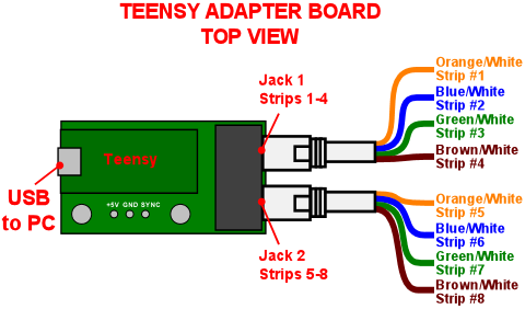
- OctoWS2811 adapter for Teensy 3.2 (interfaces the Teensy to CAT6 jacks for easier wiring to the light strips, about $10)
- A CAT6 cable to connect the light strips to the adapter
- A USB micro to USB "A" cable to connect the Teensy to the PC
The Teensy isn't a light strip controller by itself. It's just a
microcontroller (a small single-board computer). To turn it into a
light strip controller, you need some special software:
TeensyStrip Controller (GitHub)
Follow the instructions there to download the software onto your
Teensy. The project Wiki linked there also has more information about
setting up your light strip hardware, so you might look there if you
run into any issues not covered in this chapter.
Parts for the light strips
Look for WS2812 light strips on eBay.
The strips are available with 30, 60, and 144 LEDs per meter. As
you'd expect, the higher densities are more expensive. For strips
along the side of the cabinet, I'd recommend the 60/meter type.
60/meter is also good for a single strip across the back. If you're
attempting to create a DMD-like effect by using multiple rows at the
back, though, you'd probably prefer the 144/meter type there, as the
higher density will allow for better rendering of shapes across
multiple "pixels".
WS2812B strips are equivalent to WS2812. (The difference with the "B"
type is related to the physical solder pad geometry of the individual
LEDs. That makes no difference when you're buying a strip, since the
LEDs are already soldered to the strip. It would only matter if you
were buying the individual LEDs to make your own custom strip or
circuit board layout.)
You can also use WS2811 light strips, but I'd stay away from those
because they're less predictable. In particular, some of the WS2811
strips are set up so that the LEDs can only be controlled in groups of
3, not individually. The WS2812 LEDs are always individually
addressable, which is what you probably want if you're going to all
this trouble. If you do buy a WS2811 strip, be sure to check the
seller's description carefully to make sure that the elements are
individually addressable.
Power supply
The strips require a 5V power supply. You can use your secondary ATX
power supply if you have one, or a dedicated 5V DC supply. See
Power Supplies for Feedback.
Make sure that your power supply has enough capacity. Long light
strips can consume a surprising amount of power. Computer ATX power
supplies are usually sufficient for typical pin cab light strips, but
smaller "wall wart" power supplies might not have enough power for
long strips.
To determine the total power requirement, count up all of the
individual LEDs across all of your strips, and multiply the total
number by 60mA. This will give you the total current used. Many
power supplies list their capacity in Watts rather than Amps, though,
so you might have to convert. For a 5V supply, use this formula:
Watts = Amps × 5
Note that this formula is written in terms of Amps, not milliamps. To
convert from mA to Amps, simply divide by 1000.
For example, if you have two meters of 60 LED per meter strips, you
have 120 LEDs. 120 × 60mA = 7200mA = 7.2A, or 36 Watts (7.2 × 5).
Once you determine the power requirements for your LED strips, check
to make sure that your power supply is rated to deliver at least that
much power. A wall wart supply or power brick usually has markings
showing the rated Amps or Watts.
Wiring
Two connections to the LED strip are required: the power supply, and
the control signal from the Teensy.
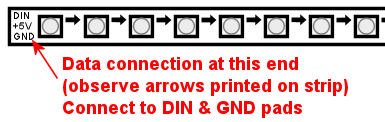
You only need a single control signal connection to each contiguous
strip. This always connects to the very end of the strip. The strips
have a directional signal flow, with arrows marked on the strip to
show the signal direction. Your data connection has to go at the
"starting" end of the strip, so that the arrows point away from that
side.
If you're using a CAT6 cable, prepare it to connect to the strip
like this:
- Cut off the plug from one end, as you need bare wires to attach to the strips
- Strip off at least a foot of the outer insulation jacket, being careful not to cut any of the wires inside. Strip more if you need to in order to make the wiring reach multiple strips.
- Carefully unwind the four twisted pairs from each other, keeping the individual pairs twisted together.
- Each twisted pair connects to one light strip. See the diagram below.

Note! The wire colors are for CAT6 cables using T568B termination,
which is how most cables are set up. However, some cables use T568A
termination, which looks the same but swaps the orange and green
pairs.
The connection from the controller uses the two wires from a twisted
pair from the CAT6 cable. Each twisted pair consists of a solid color
wire and a white wire striped with the same solid color. For example,
a solid orange wire is paired with a white/orange striped wire.
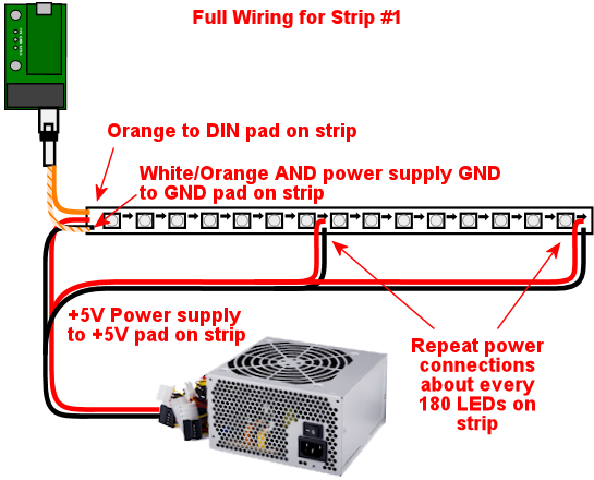
Connect the solid color wire to the DIN pad on the strip, and
connect the striped wire to GND.
For power, you must provide a separate connection at each end of the
strip, and an extra connection at least every 180 LEDs. The
extra connections are required because the copper traces on the strips
are limited in the amount of current they can carry, and every LED
between power connections adds to the current used. Multiple
connections are required to distribute the load so that the traces
don't carry too much current through a single section.
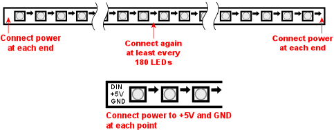
At each point where you connect power, connect the power supply's
5V terminal (the red wire on an ATX power supply) to the +5V
pad on the strip, and connect the power supply 0V/ground (black
wire on an ATX supply) to the GND pad on the strip.
For power connections in the middle of a strip, leave the DIN/DOUT
pads unconnected at that point. You only need the single DIN
connection at the "input" end of the strip.
For the power connection at the start of the strip, where you're also
attaching the data connection, note that the GND pad on the strip will
connect to both the power supply 0V/ground and the white
striped wire from the CAT6 twisted pair.
Here's a full wiring diagram for the first strip. Each additional
strip is wired the same way, but connects to a different wire
pair from the CAT6 cable: the second strip connects to the blue/white
pair, etc.
Connecting multiple strips
You'll probably have several sections of strips, in which case each
strip needs its own data input connection. There are two ways to
handle multiple strips:
- Connect each strip to a separate twisted pair in the CAT6 cables from the Teensy adapter. The adapter has plugs for two CAT6 cables, and each cable has four twisted pairs, so you can connect up to eight strips this way. See the diagram of the adapter above to figure out which wires in the CAT6 cable connect to which strips.
- Daisy-chain the strips. Using twisted pair wiring, connect wires from the DOUT/GND pads at the end of the first strip to the DIN/GND pads at the start of the second strip. Repeat for each additional strip.
Most people find the first approach (wiring each strip directly to the
Teensy adapter) to be easier and more reliable. Daisy-chaining is
possible, but you have to provide good clean connections between the
strip segments, using twisted-pair wires, to make it work. The
challenge is that the data signal operates at high frequencies and can
be very sensitive to electromagnetic interference from other devices
in the cab. Twisted pair wiring provides a degree of shielding.
Daisy-chained connections are more or less required, though, if you're
creating a matrix of strips with multiple rows. In that case you'll
probably have too many strips to use the direct connect approach.
Mounting in the cab
Most of the WS2812 strips are sold as bare strips without any adhesive
backing, so you'll have to provide your own adhesive. Most people use
double-sided foam tape.
If you're installing strips along the inside walls of your cabinet
adjacent to the playfield TV, pay attention to clearance so that you
don't make it impossible to get the TV in and out of the cab. Many
people build their cabs so that the TV is a very tight fit, so strips
that intrude even a couple of millimeters could make it difficult or
impossible to lift the TV or remove it. If the strips are permanently
installed along the inside cabinet walls, you'll be stuck without
access to the inside of the cab, which you should never let happen.
Here are a couple of approaches other cab builders have used:
- Mount the strips on a removable platform, such as a thin aluminum bar.
Attach that to the cab wall with Velcro. This makes it easy to
remove the strips to get them out of the way any time you need to lift
or remove the TV. This is the way that many pinball collectors do it
when they add similar light strips as mods to their real machines.
If you're using anything metallic as the removable platform, be sure to place an insulating layer between the strips and the metal. Many types of LED strips have exposed copper pads on the back, so they'll short out if you mount them directly to a metal surface. Foam tape is a good solution, because it can serve the dual purposes of sticking the strips to the metal and insulating the backing.
- Recess the strips into the wall, so that they don't get in the way of the TV. Use a router to cut channels into the cabinet wall where the LEDs will mount. Make the channels deep enough that the LEDs are fully recessed, so that the front surface of the LEDs is flush with the interior wall.
Available DOF effects
The DOF Config Tool provides
pre-programmed effects for the standard light strip placements. The
easiest way to set up strips with DOF is to use these programmed
effects. Here's a list of the available effects and how they're
typically assigned to physical light strips in the cab.
| DOF Effect Name | Use with | Description |
|---|---|---|
| PF Left Flashers MX | Left playfield TV strip | Simulates playfield flashers near the left edge of the playfield |
| PF Left Effects MX | Left playfield TV strip | Special effects along the left side of the playfield, such as ball chaser lights |
| PF Back Flashers MX | Playfield TV rear strip/array | Simulates a dedicated 5-flasher panel (see Flashers and Strobes) |
| PF Back Effects MX | Playfield TV rear strip/array | Special effects near the rear of the playfield |
| PF Back Strobe MX | Playfield TV rear strip/array | Simulates a dedicated strobe light (see Flashers and Strobes) |
| PF Back Beacon MX | Playfield TV rear strip/array or backbox strip/array | Simulates a dedicated |
| PF Back PBX MX | Playfield TV rear strip/array | Additional special effects used in PinballX |
| PF Right Flashers MX | Right playfield TV strip | Simulates playfield flashers near the right edge of the playfield |
| PF Right Effects MX | Right playfield TV strip | Special effects along the right side of the playfield, such as ball chaser lights |
| Flipper Button MX | Flipper button lamps | Illuminates the flipper buttons in the appropriate color for each game |
| Flipper Button PBX MX | Flipper button lamps | Additional flipper button lighting for PinballX |
| Left MagnaSave MX | Left MagnaSave button lamp | Illuminates the left MagnaSave button in the appropriate color for each game |
| Right MagnaSave MX | Right MagnaSave button lamp | Illuminates the right MagnaSave button in the appropriate color for each game |
| RGB Undercab Complex MX | Undercab lights | Ambient illumination effects for undercab lighting (see Undercab Lighting) |
DOF Setup
There are two parts required to set this up with DOF: a "cabinet
configuration" file, and the DOF Config Tool settings.
Part I: Cabinet config file. You'll have to manually create a
file on your PC called Cabinet.xml, in the DOF folder,
to describe your hardware setup for the strips.
Before you do that, though, you also have to set up a "global"
config file to tell DOF to use your Cabinet.xml config file.
(Nothing's ever easy with DOF!) That procedure is explained in
"Extra controller setup" in DOF Setup. Please read through
that section and follow the steps listed there. That will give
you a starting point for the Cabinet.xml file that you can fill
in with the light strip information.
The light strip entries in Cabinet.xml file are quite complex, and
they're covered in the Wiki page for Swiss Lizard's Teensy code, so
I'm not going to reiterate all of that here. If I copied it here, it
would just gradually drift out of date and become more confusing than
helpful. Better to go straight to the source:
github.com/DirectOutput/TeensyStripController/wiki -
see "Software: DirectOutput Framework"
Another helpful resource is this VPForums thread, which has examples of
the cabinet config file.
How to Set Up Addressable LED Strips (at VPForums)
Part II: DOF Config Tool settings. Once you have the
Cabinet.xml file set up, DOF will be able to find your hardware. But
wait! There's more! You have to go through yet another procedure now
to tell DOF to actually use that hardware.
This procedure uses the DOF Config Tool.
Hopefully you're already familiar with that from setting up your
general-purpose output controller. If not, please read through "The
DOF Config Tool" in DOF Setup.
The first step is to tell the Config Tool that you have a Teensy light
strip controller device:
- Click the "My Account" tab to go to the account settings page
- Set "Number of WS2811 Devices" to 1. (This reflects the number of Teensy light strip controllers, not the number of light strips. If you have so many strips that you need two or more Teensy devices to control them all, set this accordingly.)
The second step is to create "combined effects". This is required
because the Config Tool has multiple effects that usually end
up being assigned to the same physical light strip. The reason for
breaking these out as separate effects is that some people with very
elaborate setups might actually have a separate physical light strip
for each effect. But most people have simpler setups.
For example, the Config Tool has effects for "PF Left Flashers MX"
(simulated playfield flashers along the left side) and "PF Left
Effects MX" (other non-flasher effects for the left side). DOF
separates these effects because you could provide two separate
light strips for these effects. But most people don't; most people
just run one strip up each side of the TV. If you're in the latter
camp, you'll want to combine these into a single effect, so that
you can assign that effect to your left strip:
- Click the "Combine Toys" tab
- In the "Toy Category" column, select RGB Addressable from the drop list
- In the "Toy 1" column, select "PF Left Flashers MX"
- In the "Toy 2" column, select "PF Left Effects MX"
- Click the "Add" button and confirm the change
- Repeat for each set of combined effects you'd like to create.
- Save changes
Here's a list of the typical effect combinations:
- PF Left Flashers MX + PF Left Effects MX (use for a single physical left playfield strip)
- PF Right Flashers MX + PF Right Effects MX (for a single physical right playfield strip)
- PF Back Flashers MX + PF Back Strobe MX + PF Back Effects MX + PF Back Beacon MX + PF Back PBX MX (for a physical rear playfield strip or array)
- Flipper Button MX + Flipper Button PBX MX (flipper button lamps)
The final step is to tell the Config Tool about your physical strips
and what each one should be used for. The DOF Config Tool thinks of
the individual strips as "ports" in your Teensy controller. This is
analogous to the way the general-purpose output controllers work: in a
regular controller, you tell DOF that "port 1 is my shaker motor, port
2 is the replay knocker..."
Now, with smart strips, it's a little different, because DOF doesn't
think of smart strips in terms of physical device types like "left
playfield strip" the way it does for "shaker motor" or "replay
knocker". It's a little more abstract. The equivalent device types
for smart strips are the effects listed under "Available DOF
effects" above. Also, since smart strips are RGB devices, each
physical strip takes up three DOF ports.
So putting those together, you set up your physical strips by saying
things like "Port 1-3 is my PF Left Flashers MX strip". You can also
use any "Combo" effects you set up above: "Port 4-6 is my Combo2 strip".
- Click the "Port Assignments" tab
- Select WS2811 - directoutputconfigini30 from the Device drop list
- Set Port 1 to the effect that you want to assign to your first light strip (the strip connected as "Strip #1", the orange/white wire pair from the wiring diagram earlier)
- If you created combined effects above, you can use those by selecting "Combo1", "Combo2", etc. You can also select the individual "MX" effects from the drop list. See the list above for an explanation of the different effects and where you'd usually want to assign them.
- Since the light strips are RGB devices, the step above will actually set ports 1 through 3 as a group, for the Red, Green, and Blue channels for the device. So the second strip will be assigned to port #4, the third will be assigned to port #7, etc.
- Set Port 4 to the effect that you want to assign to your second light strip (the strip connected as "Strip #2")
- Repeat for each additional light strip
Troubleshooting the "all white" problem
A common problem that many people seem to experience when first building an
addressable light strip is that all of the lights turn on full white.
This is a result of a missing external pin connection on the Teensy. I
think this varies according to the version of the Teensy you're using,
so you should probably test first to see if you do indeed have the
"all white" LED problem. If so, the solution is to add a jumper wire
that shorts together pins 15 and 16 on the Teensy.
Here's a thread on the forums about it:
