42. Backbox Toppers
Toppers are extra decorations on top of the backbox, such as The
Addams Family's cloud or Whirlwind's fan. A few titles
over the years included toppers as original equipment, but not all
that many, so they were a great novelty feature that helped a machine
stand out from the crowd in an arcade. In more recent times, pinball
collectors have become fond of adding after-market toppers to every
machine in their collections that didn't already have one from the
factory.
Virtual cab builders like their toppers as well, but often for
different reasons. For the real pinball machines, toppers are mostly
about novelty and decoration. In the virtual world, in contrast,
toppers tend to be more about function than decoration. There are
certain feedback devices that just won't fit anywhere else,
particularly fans and beacons. We virtual cab builders tend to view
the topper area primarily as free space for feedback toys.
I think it's worthwhile in a virtual cab to take both views of the
topper - it's a functional feature, but it's also part of the artwork.
We all put a lot of effort into our cabs and want them to look as
great as they play, so it's worth thinking about how to incorporate
the topper elements into our visual themes. It's nice for the topper
to feel like a natural extension of the cabinet art, rather than just
a bunch of gadgets bolted on top.
Let's start with a look at how some of the real machines used toppers
to enhance their visual theming, to get some ideas about how we can
do the same thing.
What makes a good topper?
The obvious place to start looking for ideas for a virtual cab topper
is in the real machines. If you do a Web search for "pinball topper",
you'll find all sorts of after-market toppers for sale. Most of these
are add-ons for machines that didn't have factory toppers, though, and
for the most part they're not all that imaginative (in my opinion, at
least). A lot of them are just acrylic signs that copy some of the
cabinet artwork, and most of the rest are some little doo-dad that's
vaguely related to the theme.
The best toppers on the real machines, for the most part, are the ones
that came as factory equipment. Many of those were thoughtfully
integrated into the theme and formed a part of the overall artwork.
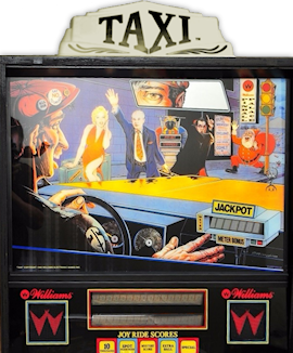
One of my favorite examples is the taxi cab roof sign from Taxi
(Williams, 1988). It's the perfect icon for the game's theme, but it
also meshes with the backglass art, sitting right on top of the taxi
depicted in the art. It's a clever extension of the backglass
painting into the 3D space above the backbox.
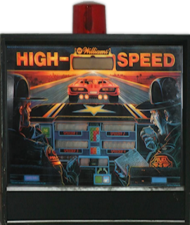
Along the same lines, a number of police-themed pinballs over the
years featured rotating beacons, or even complete police-car light bars,
as toppers. Police themes are nearly as common in pinball as in
CBS dramas, so there are lots of examples, but the canonical
one is High Speed (Williams, 1986), where the beacon fits
into the backglass art using exactly the same trick as Taxi's
roof sign:
A beacon isn't just a passive decoration, either. It can be an active
part of the game action, lighting up and spinning in sync with events
in the game. It's no wonder they used these over and over on the real
machines. They even used them in a few cases where it's hard to see
any relation to the theme. One curious example is
F-14 Tomcat (Williams, 1987), which had not one, not two, but
three beacons.
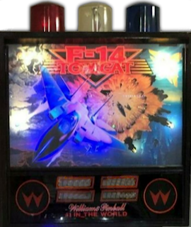
I wouldn't consider this one to be good integration of topper and
theme. Even so, it's understandable why Williams used beacons so
often, since they add not just an extra decoration, but also a
functional element, in the form of a light show.
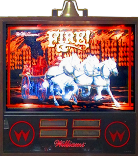
Another great functional topper is the fire bell on Fire!
(Williams, 1987). It's the sort of bell you'd expect to see on an
antique fire wagon, so it's a good theme icon, even if it doesn't meld
as seamlessly with the artwork as the Taxi sign and High
Speed beacon. Like the police beacons, it's an active part of the
game's sensory effects - it has a solenoid hammer that rings the bell
when certain events occur in the game.
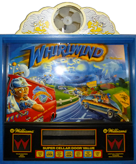
Yet another brilliant functional topper is the cloud-shrouded fan on
Whilrlwind (Williams, 1990). It's the perfect active toy for
the theme; the fan activates during multiball modes and other events
in the game, creating a tactile sensory effect from the blowing air.
The cloud shape of the enclosure meshes with the backglass artwork,
extending the stormy sky in the art into the space above the
backbox.
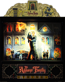
The somewhat similar cloud topper on The Addams Family (Midway,
1992) takes the same approach, and also serves as the top of the
Addams mansion, whose roof extends out of the frame at the top of the
backglass. It doesn't have anything as dramatic as the
Whirlwind fan, but it has flashers inside that simulate a
lightning storm when you start a multiball mode.
Funhouse (Williams, 1990) didn't have a topper as original
equipment, but here's an example where someone came up with an add-on
topper that's as good as anything that came out of the factory.
Heinz-Peter Bader.
designed this topper for his own Funhouse. He took a vanity
mirror light - the kind with a row of big round bulbs, like in the
stereotypical actor's dressing room mirror lights - and filled it out with party
bulbs in assorted colors, then put it on top of the machine with the
bulbs pointing up. (I've seen at least one other similar Funhouse
topper mentioned in a pinball forum, so I'm not sure who came up
with the idea first, but this is certainly a nice implementation
in any case.)
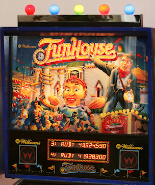
Photo courtesy of Heinz-Peter Bader
It's interesting to compare this design to the various after-market
commercial toppers for Funhouse that the "mods" companies sell.
The bulb topper works so well because it's perfectly in scale and it
captures the carnival atmosphere of the theme, plus it's a natural
extension of the backglass artwork (which is already festooned with
little marquee bulbs) into the space above. In contrast, all of the
commercial topper I've seen for Funhouse just reiterate
something from the artwork, without feeling like part of it: a giant
"Admit One" ticket, a cut-out of Rudy. They do nothing to merge with
the backglass art.
Virtual cab toppers
Virtual cab builders usually take a utilitarian view of the topper,
focusing on the functional elements. There's a fairly standard set of
feedback devices that most cab builders incorporate in their toppers:
Most cabs have at least one of these, and many use all of them.
They're all great additions functionally. Beacons, flashers, and
strobes all make nice light shows, and a fan adds a wonderful tactile
element that movie theaters would market as a "4D experience" with
a $10 ticket surcharge.
But does a big pile of devices make for a "theme"? Well, from one
perspective, it actually does. One way to see a virtual cab is as a
whole arcade's worth of pinball tables in one box. So you could say
that the theme is "all the pinballs" - which makes "all the topper
toys" an apt fit.
Personally, though, I like the idea of giving a virtual cab some kind
of theme more personalized than "all the pinballs". I discuss that
idea a bit in Cabinet Art. If you are giving your
machine a specific theme, I think it's also a nice touch if you can
extend your theme to the toppers.
Of course, functionality is still the starting point in choosing which
devices to include. I'd never suggest that you should forego a fan
just because your theme doesn't have an obvious connection to air
circulation. But maybe you can find ways to work some of the
functional elements into your theme, even though the theme isn't the
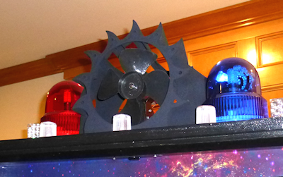
reason you included them. For example, on my cab, I came up with a
custom plastic enclosure for the fan that's meant to look like a
star-burst, to go along with the outer space theme of my cab graphics.
So I didn't really try to make the functionality of the fan fit the
theme, but I did at least try to work its shape into the visual
layout. (If you're interested in my specific topper design, you can
find some more details below.
Some ideas for how to work your toppers into a theme:
- Brainstorm for natural real-world "topper" items fitting your theme, like Taxi's sign topper.
- Think about custom enclosures for one or more of the items. The fan is perhaps the most obvious enclosure to customize (like I did on my cab), since you need some sort of enclosure anyway, and it's easy to build around a bare motor-and-blade fan core. You could also create your own custom covers for beacons or strobes, or work them into a larger enclosure like a police-car light bar.
- Consider versions of the topper devices or exterior finishes that fit your theme. For example, if you're using a steam-punk theme, give your toppers a Victorian industrial look, with brass finishes and exposed rivets.
The Pinscape topper
The topper design that I came up with for my own pin cab is very
specific to my theming, so I doubt it'll be of much interest to most
pin cab builders other than as one more example. But in case anyone
wants to reproduce it or use it as a starting point, here are some
details about the design.
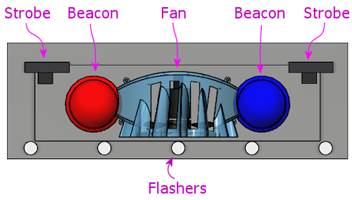
Most of the topper is made from off-the-shelf parts:
- A row of five standard pinball flasher domes with high-power RGB LEDs inside is arrayed across the front edge. These are simply wired in parallel with the main flasher board at the back of the playfield, so they always light up at the same time and in the same colors as the main flashers. See Flashers and Strobes for details on setting up a standard flasher panel.
- A pair of Peterson 771 dome-shaped rotating beacons, one in red and one in blue. See Beacons.
- A pair of "22 LED white strobes" that you can find on eBay. See Flashers and Strobes.
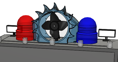
The centerpiece is a custom-built fan with a 3D-printed plastic
enclosure.
The fan is built with a generic 12V DC motor with a 1/4" shaft, mated
to a press-on plastic blade. The blade is a part originally used in
microwave ovens, Thorgren model number 6C2504C1, in black. This
happens to be the same OEM part that Williams used for the topper fan
in Whirlwind, so I was delighted to be able to find the exact
same part. But don't worry if you can't find that particular blade;
eBay has lots of similar fan blades that look just about the same.
Just look for a 6" fan blade with a shaft bore that's the same size
as your motor's shaft. A good search term to try is 6" fan
blade.
To mount the fan motor, I rigged a simple bracket using sheet metal. I
don't have any tricks to suggest here; the bracket I came up with
isn't particularly clever or elegant. You just need something that
you can attach to the motor body to hold it at the right height above
the backbox roof.
For more on building a fan like this from parts, and for details
on how to wire a fan to your output controller, see
Fans.
The fan enclosure is designed to fit between the beacon domes, to
create the impression that the enclosure and domes are connected. The
area around the fan opening is meant to suggest a blazing sun, in a
sort of cartoonish style.
You can download 3D plans for my fan enclosure in STL format here:
Note that the ZIP file contains "front half" and "back half" models in
addition to the full model. I created the half models to fit the
limits of the specific manufacturing process I used, so these probably
won't be useful unless you happen to use a printer with very similar
constraints, but I included them just in case.
There's one more detail worth mentioning: the fan enclosure is decked
out with lighting. (If you want to see it in action, I made a short
video: www.youtube.com/watch?v=wJ1czPnjvDQ.)
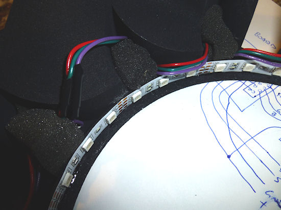
The fan enclosure has two types of lighting. The first is one of
those common 5050 RGB LED strips, installed around the perimeter of
the front fan opening. This is the same type of LED strip normally
used for under-cab lighting. If you look
carefully at the fan enclosure model, you'll see a little lip on the
inside of the opening, about 1 centimeter deep. That's the mounting
surface for the LED strip. The strip is mounted on the inside of this
lip, so that the LEDs face inwards towards the center of the opening.
This creates a nice ambient light effect inside the fan. I wired the
LED strip straight to my undercab lighting, so it shows the same
colors as the undercab lights. That creates a nice effect with the
output in DOF set to show the "undercab complex" effects, which
changes the LED strip colors in response to game events. It makes the
fan interior lighting fairly dynamic.
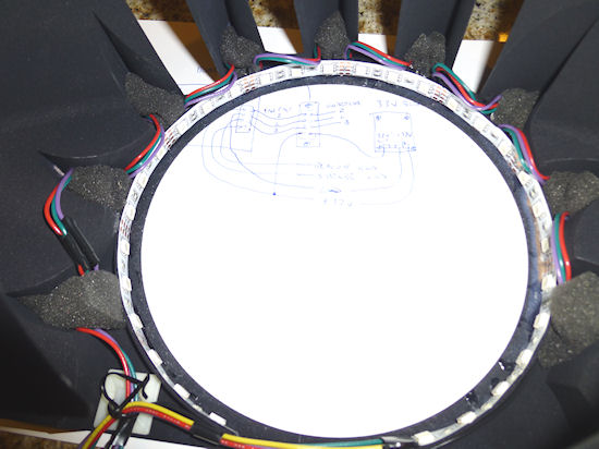
The second bit of lighting installed in the fan consists of nine
high-power RGB LEDs, arranged around the perimeter of the opening,
facing forward. Again, looking carefully at the STL model, you'll see
a small circular hole in each of the "points" of the star-burst shape.
These holes are the right size for typical 3W RGB LEDs, of the same
type commonly used for RGB flashers, but in this case, without
the aluminum "star" base that's usually used for the flashers. You
can find these LEDs on eBay by searching for "3W RGB LED" - they look
like this:
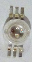
These are actually the same LEDs used in the "star base" type. The
only difference is that they're sold as bare LEDs, not mounted to the
aluminum heat sink base. The procedure for wiring them is the same as
for wiring the flasher LEDs; see Flashers and Strobes for more on
that.
The method I used to mount the LEDs in the fan enclosure is inelegant
and a little tricky (it takes some manual dexterity and a bit of
patience), but it worked well and has held up well over the several
years since I built it. I started by soldering hookup wire to the
LEDs, with just enough wire between adjacent LEDs to reach from one
hole to the next. The LEDs are wired in series, meaning that
the "+" side of one LED connects to the "-" side of the next LED, and
so on down the chain. There are no resistors in this chain - just the
wires and the LEDs. Once all of the wiring was soldered, I arranged
all of the LEDs into the desired locations, poking out through the
star-burst holes. This is the part that requires dexterity and
patience.
And now for the part that's truly inelegant. To secure the LEDs in
place, I stuffed some packing foam into the pockets behind the LEDs.
I tried some other approaches, the best hope being 3M VHB tape (which
is pretty amazing for many similar applications), but that didn't
work; it's hard to get anything adhesive to stick to 3D-printed
plastic, since the surface tends to be uneven and powdery. The
packing foam turned out to work surprisingly well, and it has the nice
feature that it's easy to remove if any of the LEDs ever needs to be
replaced or if a solder joint ever breaks.
Controlling the 3W perimeter LEDs is almost a whole separate project.
There are two main parts:
- The first is the power supply for the 3W LEDs. Wiring LEDs in series means that you need to supply them with a voltage that's higher than the sum of the VF ("forward voltage") values for all of the LEDs. For 9 of the 3W RGB LEDs, this works out to about 33V. So I used a DC-to-DC step-up buck converter to convert power from a 12V supply to 33V. (You can find such step-up converters on eBay; they run about $10 for the size needed here.)
- The second part is something to control the LEDs. You could just
wire them to your DOF output controller, and assign them to one of the
existing DOF device types, such as the strobes or under-cab lights. I
wanted something a little unusual, though, which required some more
custom electronics. What I wanted was to coordinate the LEDs with
both the strobes and the beacons: when the strobes fire, I want the
LEDs to flash white, and when the beacons run, I want the LEDs to
flash rapid red and blue patterns like a modern police cruiser. You
might be able to produce something like this with DOF directly,
but it seemed easier in this case to build a little microcontroller
project instead. As usual with microcontrollers, GPIO pins provide
the connections to the outside world: GPIO input pins connect to
the DOF outputs for the strobes and beacons, so that the controller
can monitor DOF activations on those devices, and GPIO output
pins connect to the fan LEDs, via MOSFETs. I wrote a small custom
program for the microcontroller that watches the input connections
from DOF, and when it sees one of them activate, it generates the
appropriate light show on the fan LEDs.
The ZIP file linked above (with the 3D design for the fan enclosure) contains a hand-drawn schematic for my controller circuitry, and the C++ control program for the Trinket. The program is designed to be compiled and downloaded into the Trinket with the Arduino IDE. I apologize for the rough appearance of the schematic; this is directly from my original working notes, and I haven't had a chance to clean it up into a proper presentation.
Reviewing this circuit plan with fresh eyes, I see a couple of changes I'd suggest, if you plan to deploy this in your own cab:
- Add a diode (1N4007 should work nicely) in series between each optocoupler cathode (pin 2 of the PC817) and the DOF output controller port, with the striped end of the diode on the DOF port side. This will avoid any danger of feeding back the beacon/strobe supply voltage into the optocoupler LED. (LEDs don't typically have very high reverse voltage tolerance on their own.)
- You might need to add a capacitor, connected across the Trinket power supply pins, to filter electrical noise from the rest of the system. You'll know this is necessary if the Trinket randomly resets or behaves erratically; if it's stable, don't worry about this. If you see any glitchy behavior, try adding a 0.1uF capacitor with its leads connected to the Trinket's BAT and GND terminals. Position it as close to the Trinket as practical. If erratic behavior persists, try different size capacitors, even up to large sizes like 1000uF. Sometimes two capacitors in parallel work even better than one, such as a 0.1uF and a 100uF. (Larger capacitors, 100uF and above, are usually electrolytic, which have a "+" and "-" side, so be sure to connect the marked "-" lead to the GND terminal. Smaller "disk" capacitors aren't polarized. See Capacitors for more if you're not sure.)
Note that my circuit design doesn't use conventional current-limiting resistors for the LEDs. Instead, it uses a feedback loop on the MOSFETs to throttle the current through the LEDs. I did it this way mostly because I was curious about how to create a current-limiter circuit like that. I don't think it's all that much better than the simpler approach with ordinary resistors, since ultimately it's just using the MOSFETs as variable resistors and burning off the extra power as heat, just as fixed resistors would. But it seems to work nicely, and it does have the slight advantage that you don't have to figure out the right resistor size for each channel; the feedback circuit amounts to a little analog computer that does the math for you each time you apply power.
