Michael Roberts
Draft, October, 2024
Revisions:
See also: Open Pinball Device HID
One of the big reasons to build a virtual pinball cabinet is that it lets you play virtual pinball using the authentic input controls you'd use on a real pinball machine: the mechanical plunger; the flipper buttons, Start button, coin chutes, and service menu buttons; and the whole cabinet itself, as a way to interact with the game physically through nudges. Playing virtual pinball with real controls is a very different experience from playing through a PC keyboard.
All of the devices and simulators that work with these special pin cab input devices communicate via a HID gamepad/joystick interface that was defined by the earliest commercial pinball I/O devices. In this layout, instantaneous acceleration readings are reported via a pair of joystick axes, and the plunger position is reported via a third axis. (The specific axis assignments vary across devices, but the information is always the same.)
It's obviously beneficial for everyone, in terms of maximizing compatibility and minimizing development work, to stick to a common interface. So it's hardly surprising that the design has been frozen since the earliest devices in this space. I nonetheless propose to change it. Changing it obviously requires a good reason given the benefits of inertia, so I hope to make the case in this article that the changes are worth making. The main changes I have in mind would fix some long-standing deficiencies in the existing interface that harm the simulation quality, particularly the plunger and nudge response in the simulators. These problems are fairly well understood by the simulator developers, and Visual Pinball, for its part, goes to some trouble to at least hide some of the more annoying artifacts. But the simulators can only disguise the artifacts, not fix them; the problems are embedded in the interface design, so truly fixing them requires changing the interface.
The changes I propose here are fairly small and easy to implement, both for device designers and simulation developers, but they're not band-aids or half-measures. I think they're well-grounded theoretically and actually solve the problems I've identified. My practical testing so far confirms this.
Compatibility is always an absolute requirement in any change like this. All of the changes here are designed to maintain all-way compatibility between any combination of new and old simulators and devices. Simulators and devices that adopt these changes will only be adding capabilities, and will remain fully compatible with the original interfaces. When users adopt software and devices that support the new features, it will be up to them whether to enable the new interface features or use the traditional system. This is actually all fairly easy to accomplish, since the changes are just a matter of adding some new information to the interfaces, alongside the same information that's always been there. Old simulators that don't consume the new information will just ignore it without even realizing it's there; new simulators that do know how to consume the new data will still be able to function without it, by using the traditional algorithms when connected to devices that lack the new data fields, or when the user sets the options to use only the original input model.
The first (and most glaring) area where there's room for improvement is accelerometer input for nudging. It's been clear for a long time that there's too much randomness in this. The problem is obvious enough that devices and simulators have attempted to deal with it through a number of fixes, such as "dead zone" filters. But those fixes have mostly been based on a notion that the observed problems are entirely due to noise in the sensors. It's true that the consumer-grade accelerometers in the pinball I/O controllers are noisy devices, but that's a bit of a red herring that's distracted us from more important issues in the input system.
Visual Pinball applies accelerometer input to the simulation by treating it as an acceleration. That might sound tautological, but it's worth spelling out, since it's the root of the problem I'm about to describe. VP (like any physics simulator) is a numerical integrator: it models the state of the system as a snapshot of the positions and velocities of the moving objects in the game, and evolves the model in fixed time steps. At each time step, it applies one time step worth of acceleration to each object subjected to an outside force, such as gravity or a solenoid. User nudge forces are handled at this step, as instantaneous accelerations applied to the model. Each moving object's velocity is increased by the current instantaneous nudge reading multiplied by the time step, following the basic physics formula v = a t. (Technically, nudge accelerations are applied to the moving objects in reverse, since a nudge actually moves the table, and in VP, the table defines the coordinate system. So when the table moves, everything else's coordinates change accordingly.)
This approach appears sound theoretically, until you look closely at the nature of the accelerometer inputs. If the accelerometer inputs were coming from inside the physics model, it would indeed be theoretically sound to integrate them exactly as VP is doing. But they're not coming from inside the model; they're coming from the outside world, from a physical sensor. The sensor collects samples in real time, typically on a fixed clock programmed by a microcontroller, which in turn passes the readings to the PC via a USB HID interface, which polls input from the microcontroller at fixed intervals defined in the Windows HID driver. VP reads the input on its own schedule through a series of Windows API layers.
What should be clear here is that there are several non-synchronized clock cycles involved. This results in a sample rate conversion problem: the accelerometer is taking samples at a fixed frequency, and VP is reading samples at a fixed frequency, but the two frequencies are different and aren't synchronized to a common clock. It makes matters worse that we also have the physical USB HID connection running at a third sampling rate.
The concrete problem that results is that VP reads a random subset of the samples that the physical accelerometer emits. VP misses many of the physical samples entirely because it wasn't ready to read a sample when a new one was emitted, or because the HID connection wasn't ready to poll for one at the time. VP also reads some samples more than once, for the same reasons: VP is sometimes ready to read a new sample before the HID connection has polled for a new one, so it'll see the same sample it read on the previous cycle.
So, in the simulation, a particular physical accelerometer reading might be missed entirely, applied once, or applied twice or more. A reading that's missed entirely is a physical input that has no effect on the simulation; a reading that's applied twice or three times has a correspondingly exaggerated effect on the simulation. With such a range of multipliers, it becomes clearer why nudge input can so often appear random: it actually is somewhat random, in that every reading is effectively multiplied by a random number generator picking a random number from 0 to about 3. (The distribution isn't uniform - the notional RNG is most likely to select 1 - but it's still a significant randomizing factor.)
The integration (of acceleration into velocity) effectively accumulates the random multiplier over time into an ever-growing random sum. Remember that VP increases every moving object's velocity by the current nudge acceleration on every time step. Velocities thus represent a sum over all past time of these inputs. With every input effectively multiplied by a random factor, we're also adding an ever-growing stream of random numbers into the velocity integration. This is the exact reason that VP needs its "Nudge Filter"; that filter's whole job is to cancel out the divergent sum of random numbers, which it does by artificially forcing the speed back to zero. Like any filtering, that introduces its own artifacts, making the simulation less natural. It can be visible in the simulation as a jerky motion in the moving objects that isn't timed to actual cabinet motion; that's the filter forcing the accumulated velocity back to zero on its own artificial schedule.
When I first came to understand that this is fundamentally a sampling rate problem, my intuition was to look for a way to fix it at that level, by performing a rigorously correct sample rate conversion. While that might be possible, I don't think it's practical with HID, or the right approach conceptually. HID is explicitly designed for applications that don't require the kind of precise time-based data transmission that we'd need. Other USB classes do allow for isochronous data streams, but HID has unique advantages that I don't think anyone would be willing to give up. Fortunately, there's a somewhat different approach that solves our sampling rate problem within the confines of HID, by treating the nudge force as a state rather than as a series of events.
Our core problem is that the simulator needs to know the effect that the nudges have on the velocity of the simulation objects, but it doesn't have enough information from the raw acceleration reports to perform the integration to obtain the velocity. It's not that the simulator is going about the calculation the wrong way; it just doesn't have the right inputs.
The best solution I see is to eliminate the need for the simulator to perform the velocity integration at all, by doing it on the device instead, and passing the velocity result to the simulator. The simulator doesn't have any direct use for the acceleration data; it just uses it to calculate the effect on velocity. So let's cut out the middleman and pass the information the simulator really needs, in the form of the velocity calculation.
The big advantage of this approach is that the device does have the information needed for an accurate integration. The microcontroller has real-time access to the raw samples the accelerometer emits, and it has high-precision timing information on the sampling interval. (It's probably even selecting the sampling interval.) This allows it to compute the instantaneous velocity, by doing the exact same integration that VP is currently attempting to do, but in this case with the right inputs. The device doesn't have to contend with missing or double-counted samples, and it knows the time between samples to high precision, probably to the microsecond or better. What's more, the device can perform the integration at much finer time resolution than the simulator can, because the device can sample the accelerometer at its native rate; it's not constrained by the HID polling rate. Most current accelerometer chips have sampling rates up to about 1000 Hz, which a typical microcontroller can easily keep up with.
The simulator can apply velocity inputs to the simulation just as easily as it can apply acceleration inputs. On each HID report, the device reports the current instantaneous velocity, computed from its acceleration integration. On each time step, the simulator reads the current HID velocity input, add adds the difference from the previous HID velocity input it received into the moving object velocities. This completely eliminates the missed-sample problem we had with acceleration input: if the simulator misses one or more samples, it catches up to the current instantaneous state immediately on the next sample, since the HID input always represents the current real-time velocity state. It also eliminates the double-counting problem: if the simulator sees a single HID input twice, three times, or ten times in a row, it still only applies that velocity once, since it only ever applies the difference from the prior sample it received. That's not just a bookkeeping trick that works by accident; it's actually correct for the simulator to maintain the same velocity over the multiple time steps when this happens, because that velocity is actually still current in the real-time world for as long as it's being reported on the HID input.
Velocity isn't a dimensionless quantity, so we need some kind of unit system. We can't expect devices to use the same unit system as the simulation when calculating these values, much as we never expected devices to use the simulator's native units for reporting accelerations in the traditional input system. So as with the traditional acceleration inputs, the velocity inputs must undergo a unit conversion when read into the simulator, from device units to internal simulation units.
The most straightforward way to handle this unit conversion is to make it a global, user-adjustable parameter in the simulator. Most of the simulators already handle the acceleration input conversion exactly this way; in VP's case, the unit conversion factor is the per-axis "Nudge Gain" setting. Users don't think of this as anything as technical as a unit conversion factor, and I'm not sure anyone on the VP staff even thinks about it that way, but that's really what it is. To the user, this is simply a dial that you use for tweaking the strength of the effect in the simulation, and the process for calibrating it is an empirical process of trying different settings until it feels right. All of this carries over naturally to the velocity input model, including how it can be presented to the user as a "strength" dial that's meant to be adjusted to the user's taste.
We can easily maintain compatibility between any combination of new and old simulators and devices by having devices report both the traditional raw accelerations and new integrated velocities in each HID report. This can be easily done with gamepad HIDs by assigning another pair of axes for the velocity inputs, which should be easy for devices to implement given that HID defines many more standard joystick axis types than any of the pinball simulators currently need - X, Y, Z, RX, RY, RZ, sliders, dials, wheels, hat switches. It would be an easy matter for most devices to add, say, RX/RY/RZ alongside their existing X/Y/Z. It strikes me as neatly symmetrical to keep the traditional X and Y axes assigned as the acceleration readings, and use RX and RY to report the corresponding velocities. I should emphasize that I only mean this as a default, a convention; devices and simulators should leave it up to the user to configure the actual axes, in case non-standard axis arrangements are needed to resolve conflicts with other software in a user's system.
As long as a device sends both velocity and acceleration readings in every report, the user can connect the device to older and newer simulators simply by assigning the appropriate axis pairs in each simulator's setup dialogs. There's no need to "switch modes" on the device when switching between games, as the device always sends both kinds of data unconditionally. Each simulator reads the input types it knows how to process and ignores the rest.
Similarly, simulators that adopt the new velocity-based input scheme should offer it as a user-configurable option, leaving the original acceleration-based input scheme in place as well. A user with an older device would continue to use the acceleration input setting, while a user with a new device could choose to enable the velocity setting instead. It would be up to the user with the new device to tell the simulator to use the velocity model, and to assign the velocity-based joystick axes as inputs. Simulators shouldn't assume which model is in use based on the joystick axis assignments alone; this new model shouldn't impose new limits on what you can assign to RX/RY, say, so simulators shouldn't assume that RX/RY are suddenly always velocity inputs now.
Plunger input has a weakness that's sort of the inverse of the accelerometer issue, but, curiously, ends up in the same place: velocity. Whereas the simulator can't reliably integrate acceleration readings over time to figure the effect on the velocities of the moving objects, it can't reliably calculate the first derivative of the plunger position over time to figure its speed. The simulator needs to know the instantaneous speed of the plunger when figuring out how much impulse to impart to a ball when the plunger strikes it, so inaccurate speed calculations manifest in the simulation as inconsistent launch speeds. If you repeat a gesture with the mechanical plunger exactly the same many times in a row, the simulator will launch the ball with too wide a range of different speeds, making skill shots too random.
As with the accelerometer, the problem traces to the limits of the HID interface, but in this case in a more obvious way. The core problem is that mechanical plungers move too fast: the motion is on roughly the same time scale as the HID polling interval. If you pull back a mechanical plunger all the way and release it, the main spring will drive it forward over the full travel range in about 30 to 50 ms. At the lower end of that range, that leaves room for two to three HID reports over the entire travel range - and the simulator isn't even guaranteed to receive all of them, since it might not be polling on exactly the same cycle as the HID driver. The simulator might only see one reading over the entire release motion.
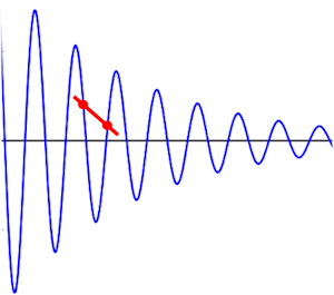
The plunger's pattern of motion creates another problem with the low sampling rate. The plunger doesn't just come to a stop when it reaches the end of its forward travel after a release. Instead, when it hits the barrel spring, it rapidly slows, and then bounces back. This makes the motion cyclical, like a classical damped oscillator. If you draw out a damped sine wave, and sample it at a low frequency relative to the oscillation frequency, you can easily contrive to pick points that appear to be forward motion, but which actually cover a full cycle of going forward and bouncing back. This is the well-known "aliasing problem" in digital sampling. You can't calculate the slope (in the case of the plunger, the speed) from these two points because they're not on the same cycle of the wave. The diagram below shows an example of this, with the two red points representing consecutive samples, and the red line representing the slope (velocity) calculated from the samples. In this example, the slope calculated is not only way off in magnitude, but also gets the direction backwards, if you're trying to interpret it as the speed at the second point in time.
Even if we could increase the sampling rate, it still wouldn't be enough for accurate speed calculations, because there's a separate problem: the HID reporting doesn't include the precise time of each reading. Since the HID reporting interval is about 10ms, the time of a sensor reading in a given HID report can be any time over the prior sampling period, so it could be anywhere from 0ms to 10ms old. That means that two consecutive samples could be anywhere from 10ms to 20ms apart in time. When the simulator calculates speed from position, it does so by dividing the difference in position by the elapsed time between the two readings. If the denominator (time) in that calculation has error bars of 100%, the result also has error bars of 100%. A calculation with 100% error bars is essentially a random number.
As with the accelerometer, the simplest and best solution that I see is to move the essential calculation from the simulator to the microcontroller. The simulator doesn't have either a sufficiently high sampling rate or the necessary sample-clock precision to calculate a meaningful result for the plunger speed, but the microcontroller has both of these. On the microcontroller side, the limiting factor in sampling rate is the sensor being used. Potentiometers can be sampled at rates up to the ADC conversion speed, which on most MCUs can be as fast as a few microseconds. Almost all of the other plunger sensors in common use can take samples at 400 Hz or faster; the slowest is probably the VCNL4010 used in the VirtuaPin plungers, which can sample at 4ms intervals. That's still fast enough to get decent speed readings over motion that takes 30ms from end to end, and to eliminate the aliasing problem we have with the limited HID reporting rate. Of equal importance, the microcontroller can know the precise time of each sample emitted by the sensor, with precisions in the microsecond range being perfectly practical to implement on most MCUs.
Unlike the accelerometer solution proposed above, where we replace the traditional inputs with the new velocity calculation, the plunger speed reading is in addition to the traditional position report. The simulation needs to know the position as well as the plunger at any given time, so the device must send both pieces of information.
As with the accelerometer additions, the new plunger speed information can be merged into the existing HID reporting structure via one of the currently unused standard joystick axes. My preference for a default convention is to keep the plunger position reading on the traditional Z axis, and add the speed reading on the RZ axis. The symmetry makes it easy to remember.
Speed is a physical quantity expressed in units of distance per unit time, so it always must be relative to some system of units for length and time. I think it's best to leave it up to individual devices to choose the unit system they wish to use, because the ideal unit system will come down to the available precision in the HID report field where the device reports this value. HID leaves the choice of these field sizes up to the device, so we can't demand universally that it always be some particular type, such as an INT16 or INT32. Some device developers might be constrained for one reason or another as to what field sizes they can use for their HID joystick layouts. Each device developer should therefore first choose the datatype that will represent the speed in the HID reports, and then choose a unit system for the speed reports such that the observed maximum speeds on the particular mechanical plunger in use will take good advantage of the available field precision, without too much risk of overflow. (If the velocity calculated on the device ever does overflow the limits of the HID field, though, the device must clip the result to fit the HID field range, so simulator will never see an overflow in any case.)
Each simulator obviously must convert the speed inputs from the HID reports into its own internal simulation unit system. If the HID report units are left up to individual devices to choose, then the simulator must use a conversion factor that varies by device. The most straightforward way to do this is to make it a user-configurable parameter. Visual Pinball and most of the other simulators already make exactly this provision for accelerometer input, for exactly the same reason; VP exposes this via the per-axis "Nudge Gain" parameters. As with nudge gain, this can be portrayed to the user in terms of its visible effect on the simulation, which in this case is something like a "Plunger Strength" factor. The conversion factor affects the simulation primarily by scaling the device speed input to impulse units when the plunger strikes a ball. (VP already has a separate "strength" factor attached to the individual plunger objects defined in tables. That has a similar mathematical role in the simulation, but a different conceptual purpose. The existing per-object strength factor is there to tweak the global level to better fit the desired feel of the individual table. The new scaling factor I'm talking about here is at the global level, something the user would see in the "Keys" dialog, with the conceptual purpose of converting the device units to simulation units. That makes it purely a function of the device, not of any individual table.)
No special provisions should be needed in new devices to maintain compatibility with older simulators. The plunger speed is just an addition to the existing model, with the position still reported as before. Older simulators that don't use the speed shouldn't even notice that it's there; it's just an extra, unused joystick axis, from the simulator's perspective.
Simulators that adopt the additional speed input should maintain their existing internal speed calculation (based as in the past on the difference between consecutive position inputs, as inaccurate as that approach is), and use it as the default way to calculate the plunger impulse. The external speed input should be treated as an optional additional axis input that the user can map into the simulation when the device is so equipped. When the speed input is enabled, the simulator should use that instead of its internal speed calculation.
The first draft of this article included a proposal for special input handling for flipper buttons, to allow the device to send flipper switch input to the host at a rate approximating the 1ms polling cycle used in the original WPC machines. Such fast switch polling might improve the simulation by more closely replicating the flipper response to extremely fast button manipulation, which is important to a few flipper tricks that advanced players can perform on the real machines. The proposal was based on the idea that native HID can't get much faster than about 8-10ms polling cycles, hence we needed a way for the device pass the host some kind of additional detail on what happened between adjacent HID reports, such as a history of presses within the polling interval, or perhaps just an indication of the fraction of the interval that the button was on.
After looking into it further, though, and doing some practical testing, I'm convinced that native HID actually can achieve fast enough polling that we don't need any extra mechanism for this. The HID drivers on Windows respect the polling interval that the device requests via the interface descriptor, and this can be set to as short as a single USB frame, which equals 1ms polling on Full Speed HID devices (which is the USB standard that most current microcontrollers implement).