Open Pinball Device HID
Michael Roberts
Draft, revised October 3, 2024
License: Creative Commons Attribution-ShareAlike 4.0 International
Status: Implemented in Visual Pinball and Pinscape Pico; not widely tested yet, but
ready for early adopters to try out
Revisions:
- 26 October 2024: removed special timing features for flipper buttons
- August 2024: first draft
See also: OpenPinballDeviceReport.h
This is a specification for a new type of USB HID interface designed
for the open-source virtual pinball community, especially the "pin cab"
subgroup who build custom systems for these games housed in real
pinball machine bodies. The goal is to define a standardized
HID interface, specially designed for the peculiar I/O needs of
virtual pin cabs, that can be implemented by pinball I/O controller
projects and by pinball simulator programs, so that any compatible
pinball simulator will be able to accept input from any implementing
I/O controller. In the long run, we aim to replace the ad hoc
joystick mappings that these I/O controllers typically use today,
to allow for more sophisticated input handling, and to reduce conflicts
with other, non-pinball video games and devices.
The special pin cab I/O controllers we're talking about are needed because
pin cab builders wish to use input controls on their virtual cabinets that
replicate the physical interaction mechanisms of a real pinball machine,
including plungers, nudging (sensed via an accelerometer), leaf-switch
flipper buttons, and arcade-style pushbuttons. The challenge is that none
of these controls can be directly connected to a standard PC; PCs don't come
with "plunger ports". Pin cab builders therefore need to use custom I/O
controller boards that provide the wiring to the various pinball-style
controls, and connect to the PC via a port that does come standard
on every PC, which these days means a USB port.
The USB port provides the physical connection to the PC, but USB isn't
just a type of hardware port. USB also has a rather complex software
model that specifies the data format and communication protocol. That's
how USB manages to serve as the connection point for devices as diverse
as keyboards, mice, disk drives, monitors, and speakers. It's not enough
for a pinball I/O controller to provide the physical wiring to a USB port;
the device also has to define its place in the USB software model. It has
to define what "kind of device" it is - is it a keyboard? a mouse? a disk
drive? - and what kind of data it sends.
The answer to the "what kind of device is this?" question is the first thing that a device
developer has to decide. The developers of the early commercial pinball controller devices
decided that they'd answer the question with "joystick". This was based
on the idea that the device had to fit some established category, and "joystick"
was the closest thing they could come up with on short notice. "Joystick" is at
least close to the mark conceptually, in that pinball and joysticks both relate to "games".
The joystick interface was also convenient pragmatically, in that it provides
an ample collection of numeric fields, which were intended to represent
the spatial positions of the various sticks and sliders and dials in an
actual joystick, but which can be repurposed in a pin cab controller to carry nudge
and plunger readings. Choosing "joystick" was also good for users, since
HID joysticks don't need any device drivers on Windows or most other operating
systems; just plug them in and go. Joysticks are even good for the programmers who
develop the various pinball simulators, since most systems have good API support
for them.
The "joystick" formulation is one of those legacy technology decisions that,
once it was made, got carried forward by inertia. It's still the standard
today; all of the later pin cab I/O controllers and simulators have just copied
the same joystick interface used by the early devices. It obviously has a lot
of pragmatic advantages, as outlined above, and it reduces work for everyone
to just keep doing it the same way. Anyone developing a new controller device
gets instant compatibility with all of the existing simulators if they use the
same interface, and anyone writing a new simulator gets instant access to
all of the existing devices. And it doesn't cause most people any trouble,
so there's no pressure from users to change it.
Like many legacy technology decisions, this one has persisted more due to
inertia than to optimality. It's not really the ideal answer to the "what kind of
device?" question. Pinball controllers aren't actually joysticks, so pretending
that they are violates a key principle of the USB HID architecture, which is that
devices should identify themselves according to the abstract function they perform.
That's important because it allows applications that want to access devices
like joysticks to do so generically, without having to be programmed with
a list of specific brand names and models they recognize. All joysticks
look the same to an application. The pinball controllers violate this by
tricking applications into thinking they're joysticks, when they're actually
something else. This might sound academic, and for the most part it is. But it
does create real problems for a small number of users. There are two specific
situations where it can cause trouble. First, users who play other video games besides
virtual pinball sometimes have conflicts with those other games taking the pinball
controller literally as a joystick, forcing the user to unplug (or at least disable)
the pinball device when running those other games. Second, users who have a mix of
pinball controllers and true joysticks (also probably for playing non-pinball video
games) sometimes have trouble getting the various games to choose correctly
among the devices when reading input. Both classes of problems can be quite
inconvenient to people who experience them, and both would easily be
solved by dropping the joystick pretense in the pinball controllers.
The missed opportunity of the early "what kind of device?" decision was
that the early developers misconstrued the problem as a multiple choice
question whose only valid answers were "keyboard, mouse, or joystick".
In fact, it's really an essay question, where we could just as well
answer "none of the above, this is a new kind of thing that you've
never heard of before". That's a perfectly valid answer in the HID scheme.
The early designers were absolutely right to choose some kind of HID,
because the magical no-device-driver feature that they knew attached to
joysticks is also true of every other kind of HID device. But that
didn't limit them to repurposing an existing concrete device type. They
could have chosen something new, avoiding any conflicts with joysticks
or other established device types.
This specification defines a new type of HID interface that can be used as
an alternative to the existing joystick input mapping.
It conveys the same information to the PC, but it uses a HID interface
that's explicitly dedicated to the pinball input function. This makes
it consistent with the way HID was meant to be used, eliminating
conflicts between pinball I/O controllers and non-pinball video games,
and also eliminating conflicts between pinball simulators and true
joysticks. This doesn't create any added work at all for device developers,
since the details of implementing the new interface are almost exactly
like implementing a joystick. There is some added work for simulator
designers, since they won't be able to use the native OS joystick APIs
with this new, custom interface. I've tried to minimize the extra
work by providing open-source library implementations
for C++ and C# that should be relatively easy to either use directly as
libraries, or as a starting point for creating a custom implementation.
In terms of compatibility, there should be no negative impacts at all,
because the new interface can be implemented alongside the existing
joystick system on both devices and simulators. The new interface amounts
to an extension to the existing systems that users can adopt at their
own pace as it becomes available in the programs and devices they use.
I said earlier that a HID device can present itself as "none of the above",
by which I mean a custom device type that no one has ever heard of before.
That's true, and it would be a suitable choice for any device type that was
so domain-specific that the USB standards bodies would never have thought of,
which certainly seems like an apt description of a virtual pinball I/O controller.
But as strange as it might seem, the HID people actually did think of it. The official
HID Usage Tables
(version 1.12) include an entry under the Game Controls usage page for "Pinball Device"
(usage page 0x05, usage 0x02). As far as I know, no one has ever implemented a
device under this usage code before. The usage code in the official tables is
little more than a name for the application domain, with almost no other
detail provided. I suspect that the people who wrote the spec were picturing
something more like a hand-held gamepad specialized for playing pinball simulations
on a game console. But nothing in the HID spec seems to limit it to that
interpretation or preclude our use case, of an I/O device purpose-built for installation
in a virtual pinball cabinet. This therefore seems like the perfect usage code for
the present design. Assuming that I'm right about there being no prior implementations,
I'm hoping this design will become the standard expression of the interface
that all of the widely-used devices and simulators will eventually adopt.
The Pinball Device defined here doesn't cover any "output controller"
features, for controlling feedback devices like motors and LEDs. It's
strictly for sending sensor and button data to the PC. That's because there are
already several device-specific output controller interfaces; in fact, there are
roughly as many of them as there are output-controller devices, since most of
the output controller devices invented their own custom interfaces. There
wasn't any existing output interface that they could co-opt (the way the
input controllers co-opted the joystick interface), so everyone just invented
their own. They therefore already satisfy our imperative to be application-specific,
although the proliferation of custom interfaces errs in the opposite direction,
creating a Tower-of-Babel problem for applications that want to communicate
with them all. Fortunately, that problem has already been solved, not by
getting all of the devices to adopt a common protocol (as we're proposing here), but
by adding a host-side API layer, known as DOF, that's device-agnostic and
which translates between the abstract API and the many unique protocols.
So, given that the main points we're trying to address
with this spec on the input side - application-specific HID interfaces and a
universal API - are already covered on the output side, I don't see any value in
including any output features in the Open Pinball Device HID design. However,
this doesn't in any way preclude Open Pinball Devices from also acting as
output controllers, since a HID device can expose multiple interfaces. A
device that wishes to implement OPD as well as output controller features
merely needs to implement a separate interface of its choosing for its
output features.
Related: Pin cab input model improvements
A separate article, Improving the Virtual Pin Cab Input Model,
describes the rationale behind some extensions to the traditional joystick-based
pin cab input model that are incorporated into the Open Pinball Device HID reports.
In particular, the new interface includes integrated velocity calculations from
the accelerometer, in addition to the traditional instantaneous acceleration
inputs; and a plunger speed calculation, in addition to the traditional plunger
position report. That article explains the purpose of the new fields and why they
can improve the simulation fidelity. The existence of the new fields doesn't mean
that simulators are required to consume them; a simulator that today only uses the
traditional joystick interface could still adopt the new HID interface without
changing any of its internal simulation algorithms, by using only the data fields
that were already part of the traditional joystick input model.
Permissions and maintenance process
I'm calling this specification the Open Pinball Device HID
to emphasize that it's meant to be an open-source, community-wide standard
that's not specific to any I/O controller or pinball simulator program,
and isn't proprietary to any vendor. This spec is published under a permissive license
(CC BY-SA 4.0)
to make it clear that not only can anyone implement what's described in the
spec, but that the spec itself can be freely revised and re-published.
Just to be clear (because this is not always a given in the virtual pinball
community's concept of "open"), the openness extends fully to commercial developers.
Vendors selling commercial devices or games are as free to implement the
interface as anyone else. This is all about interoperability, and it would
benefit users if all of their pin cab devices and software implemented
the same interfaces, so I wish to encourage uptake in commercial
products as much as in open-source projects.
I'd naturally like any future evolution of this spec to carefully
maintain compatibility with prior versions, which certainly places
some technical constraints on future changes. The specification takes
future evolution into account and includes some technical measures
to help ensure ongoing compatibility. But I'm not going to
attempt to define any particular "process" for future updates.
I'm not proposing a committee that owns it or anything like that,
and I don't want to be a bottleneck myself if anyone wants to
improve on what's here, thus the almost-no-strings license.
I think the details of this spec will only be of interest to the
relatively small group of people who work on the various virtual
pinball software components, and I expect we can manage
future changes via the informal collaboration that drives most of
the work in this space.
Implementation status
The HID interface described here is implemented on the device side
in my new Pinscape Pico project.
I've also implemented it on the simulator side in all of the Visual
Pinball branches currently being supported. In VP builds that include
the new code, the nudge and plunger axes can be assigned to an
Open Pinball Device by selecting "Open Pin Dev" in each axis drop list
that you wish to assign to the interface. That will automatically map
each axis to the corresponding Pinball Device input field by its
designated pinball function.
Rationale
The main motivation for a new HID interface type dedicated to pinball
controller devices is that it provides a possible solution to the
conflicts that some people encounter when using the traditional
gamepad mappings for their pinball input devices. In particular,
a great many non-pinball video games recognize HID gamepads
when they're attached to the system, because gamepads are very nearly
as generic a device type in the HID world as keyboards and mice.
It's generally a good thing that so many video games recognize
joysticks generically - that was in fact a major goal of the whole
HID architecture, that applications don't have to be programmed
to recognize specific brands of keyboards, mice, and joysticks
because all of these devices can be made to conform to a standard
software model that any application can interpret. But that
near-universal recognition of joysticks can be a disadvantage
when we encounter a game that would be better off not
detecting one of our specialized pinball I/O controllers, because
that particular game doesn't know quite what to do with the input
the pinball controller generates.
The root of the problem is that the pinball I/O usage of the
joystick interface is an abuse of the interface. Joystick axes
were meant to represent joysticks. Pinball I/O controllers
aren't joysticks; they only use the joystick axes because the
joystick axes offered a ready-made way to convey analog input to applications
on the PC without a lot of extra development work. Pinball I/O
controllers use the joystick axes to represent plunger and accelerometer
readings. Accelerometer readings are the main source of conflicts with
non-pinball video games, because accelerometers by their nature are always
jiggling around as they pick up small vibrations. Non-pinball video games
often interpret this constant jiggling as a nervous user attempting
to enter lots of small travel or motion commands, which can make the
playing experience for the actual user annoying or
impossible.
Joysticks can also be somewhat troublesome if you need multiple
game controllers for some of your games, because the pinball
games for the most part don't have any way to distinguish
among multiple joysticks or select a particular joystick to
use for pinball input.
Finally, joysticks can sometimes cause conflicts among games
even if you only have pinball games installed, since different
pinball games have different input requirements (which axes are
mapped to which functions, for example) that are sometimes
in conflict. Some of the simulators are more configurable
than others, and some might not be flexible enough that
you can find a single joystick configuration that satisfies every
program simultaneously.
The new Pinball Device HID can potentially mitigate some of
these problems, mostly thanks to its specificity.
Whereas HID joysticks are common, generic devices
that many video games recognize and use automatically if present,
the Pinball Device HID will go unnoticed by anyone who's not
specifically looking for it. Not because the interface is
"hidden" or somehow difficult to find, but because it identifies
itself as exactly what it is, so the only programs that will find
it are the ones that look for it. That's exactly
how HID was supposed to work. The nice thing about this
quasi-stealthiness is that it's the default state of affairs:
non-pinball video games don't have to be affirmatively programmed to
ignore the Pinball Device HID, since they'll never look for
it in the first place.
So switching one's pinball controls over to a Pinball Device HID
would be a way to resolve a conflict for a user with a game
that can't handle constant jiggling on the joystick inputs.
In the short term, pinball I/O controllers can add the new Pinball Device
interface while keeping the traditional joystick interface active as well,
since HID allows a device to expose multiple interfaces
simultaneously. This might even be the long-term situation,
since the Pinball Device interface will probably only ever be adopted
by the open-source simulators that are being actively maintained.
The joystick interface will probably always be needed for older
games, and for commercial pinball games, which probably won't bother
to learn about our little community's open-source initiatives. But
switching where we can to a more pinball-specific interface might
at least provide users who are experiencing conflicts a better
chance of resolving them.
In addition to the conflict-reduction benefits, a dedicated Pinball
Device interface might also benefit users by simplifying the steps
needed to configure individual applications. The traditional
joystick HID interfaces are only suitable for pinball I/O to the
extent that they provide multiple generic analog input axes.
There's nothing in the standard HID axis usages that ties X/Y
to accelerometers or Z to plungers; those assignments are just
arbitrary choices made long ago that have since settled in as
conventions. (The very arbitrariness of assigning X/Y
as accelerometer inputs is the source of some of the conflicts
discussed above.) In contrast, the Pinball Device
interface allows us to define an I/O report structure with
dedicated fields for the specialized pinball-related sensor
inputs, not as generic inputs that happen to contain
accelerometer and plunger sensor readings, but as inputs
specifically designated in the report structure as accelerometer
and plunger sensor readings. This means that applications don't have
to guess about which field has which pinball-specific meaning, and
therefore don't have to rely on users to tell them. It would
be enough for a user to check a box saying "Use Open Pinball Device"
to fully configure an application with the appropriate inputs,
since the application knows without being told which
field in the Open Pinball Device report is Acceleration X
and which is Plunger Position.
It might also be worth mentioning why we chose to make this a
USB HID interface, as opposed to some other USB device class.
While this might seem the obvious choice, as a natural migration from
the traditional keyboard and joystick interfaces, there are also
some solid technical reasons to choose HID on its own merits.
First, HID has built-in device driver support on all desktop
operating systems relevant to virtual pinball players. And it's
a core device type on all systems, on par with other critical
devices like storage and graphics, so HID support is robust and
well integrated on all systems. Second, thanks to the built-in
device drivers and the HID's plug-and-play architecture, HID
provides a frictionless experience for users. Device recognition
is automatic and dynamic at the OS and application level; newly
plugged-in devices can be used almost instantly without any
driver installation or other user intervention. Third, the HID
device drivers on all systems allow easy, robust sharing of a
device across applications. Multiple applications can read from
the device simultaneously without any sharing conflicts. This
is inherent in the stateless design of the HID protocol, so
OS HID device drivers can readily pass the sharability along to
applications. This is a strength almost unique to HID; few of
the other USB classes are as easily sharable at the application level.
And finally, HID is a perfect fit conceptually. HID stands
for Human Interface Device, and the Open Pinball Interface is
manifestly a human interface device: it takes input from the
user in the form of nudges, plunger gestures, and pushbutton
presses, and sends the input to the PC. Even without the
technical advantages that HID offers, HID would be the
conceptually correct USB class to use for this device type.
Devices and simulators
There are two "parties" that we frequently refer to in this spec:
devices, which are microcontroller-based systems where
input sensors like accelerometers and plunger are physically
connected, such as the Pinscape Controller or the VirtuaPin
plunger kit; and simulators, which are PC-based video-game
applications, such as Visual Pinball or Future Pinball, that
simulate pinball play on the PC.
Devices implement the Pinball Device HID, and send data through the
interface. Simulators act as clients to the interface, reading data
from the interface to apply in the simulation.
General description of what the device sends to the host
HID reports sent through the Open Pinball Device contain the following elements:
- Nudge, as X/Y accelerations: This is the traditional
way that devices convey nudge input to the simulator, as
instantaneous acceleration samples read from the accelerometer.
- Nudge, as X/Y integrated velocities: This is a new
way to handle nudge input, which has the device integrate
acceleration readings to compute the implied instantaneous
cabinet velocity. This has some advantages over the traditional
acceleration model that might improve the playing experience
by making the nudge information seen in the simulation more
accurate. This is optional information that not all devices
provide.
- Plunger position: The position of the mechanical
plunger along its axis of motion.
- Plunger speed: The instantaneous speed of the
plunger. A standard mechanical plunger moves so quickly
during a pull-and-release event that it's impossible for the
host-side software to meaningfully calculate the speed
as the first derivative of sequential position reports
across USB, since the USB reporting cycle is simply too
slow. The device, however, typically has fast enough
access to the sensor that it can accurately
calculate the speed even during these high-speed motions.
This field allows the device to report its calculation
of the speed, which the simulator can use for a more
accurate determination of the momentum transferred to
the ball when the plunger strikes it. This is optional
information that not all devices provide.
- Pushbuttons: A collection of 64 digital
(on/off) button states. 32 of these are assigned
specific pinball-related meanings. This reduces the
amount of configuration work for the user: the user
only needs to assign the physical inputs in the device
to the corresponding pinball button function, and
doesn't have to repeat the process in the pinball
simulators, since the simulators already know the
meaning of each button.
32 additional button slots are defined as "generic",
allowing them to be used for any other purpose
not already covered by the pre-defined button list.
These can be used for special functions defined
by individual pinball tables, or extensions to
the standard set defined by individual simulators.
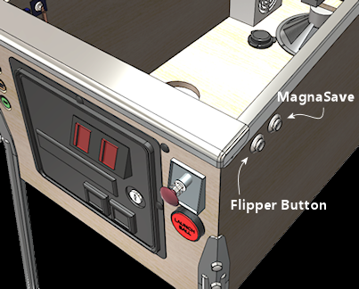
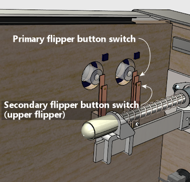
- Flipper buttons: The pinball-specific
buttons include slots for four flipper button switches,
to accommodate double-stacked leaf switches on the flipper
buttons. Double leaf switches are commonly used on
physical pinball machines that have extra flippers, to let
the player independently control an upper flipper while
holding a ball trapped on the lower flipper. Many virtual
pin cab builders use the same double switches to replicate
that detail of the original playing experience, so we
include dedicated mappings for them. Cabinets that use
single-pole switches for the flipper buttons can simply
map the single physical switch to trigger both the primary
and secondary logical switch on that side, and simulators
that don't distinguish the secondary switches can simply
ignore the secondary switch inputs.
Note that the secondary flipper switches aren't meant
to be mapped to secondary buttons. Many virtual
pin cabs also include a set of "MagnaSave" buttons,
which are secondary buttons positioned adjacent to the
regular flipper buttons. Those have a different semantic
assignment from the secondary flipper switches,
so they have their own dedicated slots in the
pinball-specific button collection.
Interface design
Open Pinball Device is a USB HID interface.
A HID device sends input to the PC in the form of a "report",
which is similar to a C struct: an array of bytes that's
structured into a collection of fields of defined datatypes,
with defined meanings. The HID report layout is expressed in
a separate object, known as the Report Descriptor, that the
device sends to the host during connection setup. The report
descriptor is analogous to a "struct" declaration in C source
code, in that it describes the contents and layout of the
data structure in a machine-readable language; and the report
itself is analogous to an instance of the C struct.
The fields in a report are known in HID parlance as "usages".
In the C structure analogy, a "usage" corresponds to a struct member
variable. Each usage in a report descriptor is identified by a code
number (confusingly also called a "usage") that describes the meaning
of the field in functional terms, such as "Joystick
X Axis" or "Keyboard Enter Key". The USB standards body
(USB-IF) publishes a gigantic list of pre-defined usage code number
for all sorts of common device classes. Among those published codes
is the Pinball Device type. Pinball Device is what's known as an
Application Collection, making it a peer of Keyboard, Mouse, Gamepad,
and other things we'd think of as discrete physical units with USB
cords coming out the back. But USB also allows these to be virtual devices,
where one physical box presents itself to the PC as a combination
of several interfaces, such as a keyboard and gamepad at once.
That's how most of the existing pinball I/O controllers work, and
what we're contemplating here is simply adding one more virtual
interface - Pinball Device - to the mix.
The USB tables also include a few usages for specialized
pinball-related elements that a Pinball Device might include
in its reports, including "Bump" (nudge input) and
"Shoot Ball" (plunger). A first glance at the table would
suggest that those should be part of our specification. But
they're not! We take a different, somewhat unusual approach.
We use a HID extension mechanism that allows a device to define its
own custom, application-specific usages. Briefly, the
pinball-related usages that the USB people defined aren't
well enough developed for what we have in mind, so we're
defining our own custom ones instead.
The way this custom extension mechanism works is that the device
labels its special usage item - that is, a custom data field in
the report that has a special application-specific meaning - with a
string name. The string doesn't refer to anything in the USB
standard; it's a string specifically so that it can be custom.
The idea is to give it a unique name that applications which are
specially programmed to work with this special device type
can look for, to identify it as the special information that
this device provides. Applications that aren't programmed
to work with this device won't recognize the string and will
ignore the custom data. Compatible applications will know by
recognition of the unique string what the special field contains and how to
parse it and process it. For our purposes, we use this custom
label string mechanism to label a C-like data structure
that contains all of the pinball data the device reports.
When a device uses this approach, the operating system's HID
driver will still work with the device as normal, but it won't
attempt to parse the custom data. It'll just treat it as an
opaque block of bytes, and pass it straight through to applications
that ask for it.
There are a couple of reasons we use this opaque-to-the-HID-driver
struct, instead of labeling the individual fields with standard
USB usage codes.
The first is that there's no particular advantage to using any
of the pre-defined usages here. It's true that the USB tables
provide us with some domain-specific usage codes, such as Bump
and Shoot Ball. In principle, if we labeled our fields with
these usages, some future commercial game might come along that
will look for Nudge and Shoot Ball usages, and magically work
with our devices. But there's a snag: the standard pinball
usages are far too inchoate to serve as a common basis for
data interchange. The Nudge usage is described as something
that could be an accelerometer reading, but could just
as well be a button press. If a commercial game does come along
that looks for a standard Nudge usage, I don't think there's any
chance it'll be able to make sense of our version
of Nudge. That game will just assume it's the Nudge format
for whatever device they tested against, which is probably
a device the same company is trying to sell. If they happen to see
our data instead, it'll probably just confuse them.
That defeats the whole purpose of a standard usage,
which is that two parties that have never heard of each other can
interchange data without reading each other's specs. If they
have to read our spec anyway, then there's no value in giving
the field a standard name, and in fact every reason not to, so
that we can be sure that incompatible applications don't try
to read our data and thus don't get confused by it. We don't
want to re-create the joystick compatibility conflicts that
exist today in a new device type.
The second reason to use the opaque type is that it has a
practical benefit to applications: applications can bypass
the operating system HID parser APIs and work with the structure
data directly. That's just easier, it turns out. The HID
parser API on Windows is complex, and rather tedious to use,
and adds run-time overhead. Parsing a pre-defined C struct
is straightforward and highly efficient.
Interface is input-only
HID interfaces are allowed to transmit reports in both directions
(device to host and host to device). To keep things simple, the
Open Pinball Device interface is input-only, meaning that it
only sends reports from device to host. We don't define any report
type for host-to-device transmissions. This one-way data flow is
typical of input devices like gamepads and mice.
HID input reports are always solicited by the host, never initiated
by the device. At the simplest level, the device can send a report
every time the host polls for one, whether or not it has anything
new to report. Alternatively, the device can respond with a NACK
when polled if it has nothing new to report.
How to implement in a host application
For a full example, see pininput.cpp in the Visual
Pinball repository on github, at
github.com/vpinball/vpinball.
Device recognition: Using the appropriate operating system APIs,
enumerate active HID interfaces. Filter for interfaces with Usage Page 0x05
(Game Controls), Usage 0x02 (Pinball Device). For each device found,
enumerate its report descriptors. Filter for interfaces with a single
report descriptor, containing a single usage that has an associated String
Descriptor, which contains the string "OpenPinballDeviceStruct/1.0".
(Per standard USB conventions, the string is encoded as 16-bit Unicode characters.)
For an example implementation of automatic device discovery written in C++, using the portable
hidapi library
(without the need for any platform-specific API calls), see
src/core/pininput.cpp
in the Visual Pinball source code (as of 10.8.1). (That code also depends
upon a portable utility library that parses HID report descriptors, which
is also in the VPX source tree, under third-party/include/hid-report-parser/.)
Note: see Versioning the report structure for a more
complete description of the recommended algorithm for matching the string
descriptor. The descriptor obviously includes a suffix that's meant as
a version number, so it requires a little more subtle treatment than
just literally matching it to reference text.
Reading reports: Once you've identified the interface, open an OS file
handle on it. On Windows, this acts like an ordinary file handle that you
can use in ReadFile(), which has the effect of reading one report packet
at a time from the device. The underlying OS HID driver automatically
polls the device for input in the background, so the application isn't
responsible for driving the polling timing; instead, the application
can read at any time from the internal queue of recent reports that
the HID driver maintains. The application view is thus a simple pipe-like
handle that blocks until a new report is available and then returns the
report. Applications typically use non-blocking read calls when reading
from a HID device, but that's a matter to consider in the overall
application design.
Parsing reports: The result from reading the OS pipe will be
a byte array representing one Open Pinball Device HID report. The report
conforms to the C structure defined in Custom Struct Layout
below. All integer fields are explicitly little-endian, so you should
treat them as byte streams to be converted to the local integer representation.
The methods to do this are straightforward and widely published on the Web, so we
won't detail them here.
The byte packet read from the operating system might
contain a one-byte prefix containing the HID Report ID. That's not part
of the Open Pinball Device report struct; it's a separate prefix included
in the HID USB packet that wraps the report struct for transmission across
the wire. Some OS APIs include this prefix when reading a raw packet from
a HID driver, and others automatically strip it, on the theory that it's
internal HID protocol information. The Windows APIs all leave the prefix
in place. If the API you're using doesn't
remove the prefix byte, the Open Pinball Device struct portion will start
at the second byte of the data read from the pipe. The presence or
absence of the byte is a function of which API you're using, so it's not
something you need to "detect" or make into a run-time condition; it will
always be one way or the other for a given API, so you just have to figure
out how the API you're using handles it and interpret the byte packet
accordingly.
Device identification
You might notice that the section covering device recognition above never
mentions the terms "VID" or "PID". These refer to the Vendor and Product ID
codes that every physical USB device provides during connection setup,
to identify itself to the host. Many application developers working
with USB devices are accustomed to searching for specific types of
devices by their predefined VID/PID combinations, so you might expect
to find a VID/PID specification here. But there isn't one! The Open
Pinball Device interface isn't identified by a VID/PID. In the USB
architecture, a VID/PID identifies an entire physical device, and applies
to all of the interfaces that the device exposes. But the whole point of this
specification is to define a universal interface that any device with
virtual pin cab I/O features can implement, so we can't specify
a VID/PID that everyone has to use. Doing so would make it impractical
to add the interface to existing devices, and would be unacceptable
to developers working on new devices, since there are good reasons
for each device to use its own VID/PID that uniquely identifies that
particular device type.
This design is good for applications, because applications have no need
to hard-code a list of predefined VID/PID identifiers that they recognize.
The recognition algorithm allows positive identification for any device
that implements a conforming interface, and will correctly identify
future devices with no need to update old applications. With traditional
VID/PID-based recognition, it was common to have to recompile an application
every time a new device came on the scene, because everyone would have to
add that new device's VID/PID to their hard-coded list. This design eliminates
that ongoing maintenance problem.
How to implement in an I/O Controller device
Devices that implement HID interfaces declare them to the host via HID
Interface Descriptors, which are part of the USB Configuration Descriptor.
We won't cover those here because they're standard USB elements that are
widely documented on the Web. The only part that's special to this specification
is the HID Report Descriptor for the Open Pinball Device type, which is shown
below.
The HID polling cycle is driven by the HID
driver on the host machine. Your HID Interface Descriptor specifies the
requested polling rate, which is expressed in units of USB frames, which
are equal to 1ms on a Full Speed USB 2 device (the standard implemented
by many current microcontrollers). To minimize latency, specify the
minimum polling of 1 frame. In addition, it will minimize latency if
you don't share the HID Interface Descriptor containing the
OPD report type with any other HID report types, because each polling
cycle can only transmit one report. If your device implements other
HID interface types, such as keyboard or gamepad inputs, you should
define those under separate HID Interface Descriptors so that they're
on separate polling cycles. The USB standard allows a device to
expose multiple Interface Descriptors, so you can create as many
different HID Interface Descriptors as you like.
HID Report Descriptor
Include this report descriptor in the HID Interface Descriptor that represents
the Open Pinball Device. Note that your device can include other, unrelated HID
Report Descriptors as well, since HID allows a single physical device to act as
any number of logical devices; so you can also send keyboard and joystick reports,
for example. However, as mentioned above, mixing multiple report types within
a single HID Interface Descriptor can increase latency, because only one report
can be sent to the host on each logical interface during each polling cycle.
The descriptor below is defined in terms of pseudo-code using the standard
USB documentation conventions.
    HID_USAGE_PAGE (HID_USAGE_PAGE_GAME),            // HID_USAGE_PAGE_GAME = 0x05
    HID_USAGE      (HID_USAGE_GAME_PINBALLDEVICE),   // HID_USAGE_GAME_PINBALLDEVICE = 0x02
    HID_COLLECTION (HID_COLLECTION_APPLICATION),
        HID_REPORT_ID     (OPENPINDEV_REPORT_ID)     // OPENPINDEV_REPORT_ID is device-defined

        // OpenPinballDeviceReport struct
        HID_REPORT_ITEM   (OPENPINDEV_LABEL_INDEX, RI_LOCAL_STRING_INDEX, RI_TYPE_LOCAL, 1),  // OPENPINDEV_LABEL_INDEX is device-defined
        HID_USAGE         (0x00),            // usage 0x00 - undefined/vendor-specific (opaque data for application-specific use)
        HID_LOGICAL_MIN   (0x00),            // byte range
        HID_LOGICAL_MAX   (0xFF),            //   00-FF
        HID_REPORT_SIZE   (8),               // 8-bit bytes
        HID_REPORT_COUNT  (sizeof(OpenPinballDeviceReport)),   // number of bytes == packed struct size
        HID_INPUT         (HID_ARRAY),       // input (device-to-host), array
    HID_COLLECTION_END
The following constants shown symbolically above are up to your
device to define:
- OPENPINDEV_REPORT_ID: a byte value, 1 to 255, giving the
HID Report ID that you're assigning to this report type. Each HID
Report Descriptor that you define across your entire device must
have a unique Report ID that you assign. The host uses this to
determine which reporting descriptor it should use to parse a
report. The number has no other meaning, so you can assign any
value you like, as long as it's non-zero and unique across all
of the HID report types you define.
If your device implements only this one report type,
and no others, you can omit the report ID entirely. (That
effectively makes the report ID 0, which is a special reserved
ID meaning "no ID at all".) If your device exposes other
HID interfaces, though, a report ID is required to
distinguish the report types on the host.
- OPENPINDEV_LABEL_INDEX: a byte value that gives the
string descriptor index of a string descriptor you provide,
containing the text "OpenPinballDeviceStruct/1.0".
USB devices generally provide a set of string descriptors
for the pre-defined fields in the Configuration Descriptor:
product name, manufacturer name, and serial number. This
custom descriptor should be added alongside those standard
strings, and you must of course assign it a unique index.
That index is what you put here. This uses the HID report
feature that lets the device assign a string label to a
usage (a data field in a report structure) to identify it
as a custom type. We use this to identify our custom
data structure, represented the report as an array of
bytes of the same size as the packed structure.
String descriptor for usage label
As mentioned above, the device must define a custom String
Descriptor containing the usage label for the custom struct
in the HID report. The string must contain the following
text:
"OpenPinballDeviceStruct/1.0"
(The enclosing quote marks are not part of the string text.)
As always for USB string descriptors, the string text must
be encoded with 16-bit Unicode characters, in little-endian
byte order.
Custom struct layout
In the HID report, we define the data sent to the host as an opaque
array of bytes. The HID driver therefore won't attempt to parse
that; it'll just pass the byte array to an application that asks
for it. The application can then interpret the byte array as our
custom struct type, shown below.
   struct OpenPinballDeviceReport // PACKED, LITTLE-ENDIAN
   {
       uint64_t timestamp;       // timestamp, microseconds since an arbitrary zero point
       uint32_t genericButtons;  // button states for 32 general-purpose on/off buttons
       uint32_t pinballButtons;  // button states for 32 special-purpose pinball buttons
       int16_t axNudge;          // instantaneous nudge acceleration, X axis (left/right)
       int16_t ayNudge;          // instantaneous nudge acceleration, Y axis (front/back)
       int16_t vxNudge;          // instantaneous nudge velocity, X axis
       int16_t vyNudge;          // instantaneous nudge velocity, Y axis
       int16_t plungerPos;       // current plunger position
       int16_t plungerSpeed;     // instantaneous plunger speed
   };
Since this struct is passed across the wire, it's also necessary to
define the byte order, so that both sides of the connection use the same
representation regardless of local CPU conventions. Therefore we require
that all integer types are little-endian (least significant byte first),
per the standard USB conventions. If the device or host uses a different
convention for local memory access, it must convert to standard little-endian
format when sending data, and convert from little-endian back to local format
when receiving data.
Note that this uses integer types defined the standard C++
header file <stdint.h>, so that file must be #included
in code using the struct declaration. When using this struct in a C++ program,
you should add compiler-specific syntax (if available) to define the struct as
"packed", meaning that the compiler must not add any alignment-related
padding between struct fields. (The C++ language doesn't provide standard
syntax for declaring that, but most compilers have extensions for it.)
The struct is arranged in such a way that all fields will be naturally
aligned without any additional padding on most current architectures, but
this might not be true on all future platforms, and in any case,
some compilers might want to add padding for optimization purposes, so
it's safest to explicitly tell the compiler that the layout is to be taken
literally.
Depending upon the host operating system, raw byte packets read from the
USB pipe might or might not include the HID Report Type byte prefix. Some
operating system APIs pass this through to the application, and others
remove it. A HID report going across the wire always includes a one-byte
prefix that specifies the report type, selecting which HID Report
Descriptor it corresponds to. Some OS APIs that read HID packets leave
the prefix byte in place in data returned to the application, while
others strip it and return just the payload. If the API you're using
to read reports leaves the byte in place, the struct will start at the
second byte of the packet you read from the API.
Timestamp
This field gives the time the report was prepared on the device side,
in microseconds since an arbitrary zero point. Applications can use this
field to determine if the device has sent a new report since the last time
they checked. That can't always be determined at the HID API level,
since HID APIs usually treat these reports as "state" information,
meaning that a "read" API will just keep returning the same report
over and over for as long as it's the most recent. For an API that
behaves like that, you can use the timestamp field to determine if
the device has in fact sent a new report since your last check.
Applications should rely on this as a precise measurement of the time
between sensor readings, because it only indicates the time the report
was created, not the time the sensors were last read. It doesn't even
represent the exact time the report was sent across the wire, because
that timing is controlled by the host, not the device.
Generic button states
This field has room for 32 general-purpose pushbuttons, one bit per button.
The least significant bit is arbitrarily labeled button #1, and the remaining
bits are numbered sequentially, with button #32 in the most significant
bit. A bit value of 0 means the button is currently OFF, 1 means it's
currently ON. The numbered buttons have no pre-assigned meanings; it's
up to the device to map the numbered button slots to physical inputs, and
it's up to each application to define the function of each numbered button
within the application.
Nominal buttons that aren't actually configured on the device should
simply be reported as always '0' (off).
Buttons are reported as states, not events, so the device simply reports
the current state of each button in each report. However, devices are
free to skip reports where nothing has changed, so the host must
assume that the state of each button from the last report remains in
effect until it gets a new report saying otherwise.
Even though the button states are "instantaneous", the device can
sample the buttons at a higher rate than the USB reports, and is free
to report that the button was ON for a report even if it switched on
and then back off in the course of the report. Or vice versa: it can
report the button as OFF if it started ON, switched briefly OFF, and
switched back ON before the end of the report. This approach ensures
that brief taps, faster than the USB cycle, are still visible to the
host as single-cycle activations or interruptions.
Pinball button states
This field has room for 32 additional buttons, in addition to the
generic pushbuttons, for pre-defined pinball-specific button functions.
This field works exactly like the generic buttons field, with each
bit representing the instantaneous state of one button. The only
difference is that the bits in this field are associated with buttons
with specific pre-defined meanings, as shown in the table below.
Bits not defined are reserved for future use and should always be
set to zero.
| Index | Bit mask | Function |
|---|
| 0 | 0x00000001 | Start (start game) |
| 1 | 0x00000002 | Exit (end game) |
| 2 | 0x00000004 | Extra Ball/Buy-In |
| 3 | 0x00000008 | Coin 1 (left coin chute) |
| 4 | 0x00000010 | Coin 2 (middle coin chute) |
| 5 | 0x00000020 | Coin 3 (right coin chute) |
| 6 | 0x00000040 | Coin 4 (fourth coin chute/dollar bill acceptor) |
| 7 | 0x00000080 | Launch Ball |
| 8 | 0x00000100 | Fire button (lock bar top button) |
| 9 | 0x00000200 | Left flipper button, primary switch |
| 10 | 0x00000400 | Right flipper button, primary switch |
| 11 | 0x00000800 | Left flipper button, secondary switch (actuates upper flipper) |
| 12 | 0x00001000 | Right flipper button, secondary switch (actuates upper flipper) |
| 13 | 0x00002000 | MagnaSave left |
| 14 | 0x00004000 | MagnaSave right |
| 15 | 0x00008000 | Tilt bob |
| 16 | 0x00010000 | Slam tilt |
| 17 | 0x00020000 | Coin door switch |
| 18 | 0x00040000 | Service panel Cancel |
| 19 | 0x00080000 | Service panel Down |
| 20 | 0x00100000 | Service panel Up |
| 21 | 0x00200000 | Service panel Enter |
| 22 | 0x00400000 | Left Nudge |
| 23 | 0x00800000 | Forward Nudge |
| 24 | 0x01000000 | Right Nudge |
| 25 | 0x02000000 | Audio volume up |
| 26 | 0x04000000 | Audio volume down |
Flippers: Each flipper button is assigned two switch slots, one for a "primary"
switch and one for a "secondary" switch. These represent the two contact
points in the stacked double leaf switches commonly used for flipper buttons
in physical pinball machines with extra upper-playfield flippers. The secondary
switch is there to allow a player to independently control an upper flipper
while holding a ball trapped on the lower flipper. Many virtual pin cab
builders use the same double switches, to replicate this detail of the playing
experience. Cabinets that use plain leaf switches for their flipper buttons
should map each physical flipper switch to trigger both the primary and
secondary logical switches; simulators that don't distinguish the primary
and secondary switches can simply ignore the secondary switch inputs.
MagnaSave: These are for extra buttons located adjacent to the flipper
buttons on the sides of the cabinet. They usually look exactly like flipper
buttons, but they don't activate flippers; they instead trigger other features
that are special to each game, such as the trademarked ball-save magnet
feature that they're named for.
Tilt and nudge: The tilt bob and slam tilt inputs are for replicas of
the mechanical anti-cheating switches found in real pinball machines. These
are meant to trigger tilt penalty conditions on the games, ending the current
ball or the whole game; they're not meant to affect the simulated
physics in any way. In contrast, the left/forward/right nudge inputs are
for virtual nudging, imparting a simulated acceleration to the simulated
playfield in a particular direction. Desktop pinball simulators traditionally
had to implement nudging with button presses like this, because traditional
PC keyboards aren't especially responsive to body English. In modern virtual
pin cab construction, button-based nudging has mostly been supplanted by
accelerometer input, so these inputs will generally go unused in a full
pin cab setup. They might still be useful for applications where accelerometer
nudging is impractical but an I/O controller is still used, such as mini cabs
or desktop controllers.
Nudge accelerations
These fields represent the instantaneous acceleration readings
from the accelerometer. These readings are typically processed on
the device to remove any constant offset from the slight installation
tilt that's almost always present, and might also be filtered for
noise, such as by applying a dead zone, or a hysteresis filter,
or a digital band-pass filter algorithm tailored to the sensor.
In addition, the readings might be averaged over the USB polling
cycle, since accelerometers typically can be programmed to take
samples at a much higher frequency than the USB HID cycle allows.
If no accelerometer is present, the device simply reports 0 in
these fields.
After any processing the device performs, the values should be
scaled to 16-bit signed integers. The values must be linearly
proportional to the analog acceleration measured on the device.
We intentionally leave the unit system unspecified, so it's
up to the device to define the physical acceleration
corresponding to full-scale in the 16-bit integer fields.
This is necessary because different accelerometer chips have
different native ranges, and it's generally best for the device
to base its scaling on the native range of the chip in use.
Simulators should therefore provide a user-configurable
scaling parameter that lets the user adjust the strength of
the effect in the simulation. Visual Pinball's "Nudge Gain"
settings serve this purpose, for example.
Nudge velocities
These fields represent the velocity calculated by the device
by integrating acceleration readings over time. On each report,
the device should provide the current instantaneous integrated
velocity result.
It's optional for the device to calculate the velocities. If
it doesn't, it can simply report 0 in these fields. The simulator
can determine if velocities are being provided by initially assuming
they're not, and changing its mind as soon as a non-zero value is
reported here. Alternatively, the simulator can let the user
tell it via a configuration option. Simulators are also free to
ignore the velocity inputs in favor of the instantaneous
accelerations, if their physics models don't allow for velocity
input.
It's better to calculate velocity on the device side, and use
that as input to the simulation instead of the raw accelerations,
because the device can do the integration more accurately than
the PC host can. The device has direct access to the raw accelerometer
data, along with precise sample timing measurements. The simulator
can't meaningfully integrate accelerations received over the USB
connection because it can't sample the accelerometer at a high
enough frequency, and it doesn't have precise information on the
timing of samples. This has been a major obstacle in the past to
realistically modeling nudge reactions in the simulators.
Performing the integration on the device side and passing it in
the USB data can improve the physics modeling and provide a more
natural nudge response.
It's up to the device to define the unit system for the
velocity data. This is probably best handled as a user-configurable
parameter on the device, so that it can be hand-tuned to the
individual cabinet's dynamics. Important: the user should be
advised that such a device-side parameter is not intended to adjust the
strength of the effect in the simulation. The goal is to take advantage of the available
precision in the 16-bit field, by selecting a scaling factor
that makes the largest nudge velocity readings observed in practice
on a given cabinet to yield readings close to full scale in the
16-bit field, without overflowing it.
Separately, the simulation should also provide its own
user-configurable scaling factor for converting the
values in the 16-bit integer fields to simulation velocity
units. This is the equivalent of Visual Pinball's "Nudge Gain"
settings. This is where the user should adjust the strength
of the effect in the simulation, after first setting on the
appropriate device-side scaling factor.
Advice to device implementers (the following is by way
of recommendation only, not normative): Integrating the accelerometer
readings over time is essentially just a matter of adding up
all of the readings to date (from reboot time), multiplying
each acceleration by the elapsed time between readings. In
most case, the accelerometer will be programmed to take
samples at fixed time intervals, so the elapsed time between
readings is always the same and can be normalized out, by
rolling it into whatever unit system you use internally
for the velocity sums.
Adding up an indefinite series of readings has the obvious
danger that the sum will grow without bound over time.
In the case of a pin cab, in principle the accelerations
should always add up over time to zero, because the cabinet
never actually travels anywhere. Any velocity it acquires is
temporary, from the cabinet swaying on its legs, and will
eventually be reversed by opposite accelerations that bring it
back to the original position and bring the net velocity to zero.
So as long as the acceleration readings are perfectly accurate,
they must always sum to zero over time, since the
cabinet's actual physical velocity always returns to zero
after each momentary displacement. The only problem here is
that accelerometer readings aren't perfect; they contain some
amount of measurement error and noise. So even though the
true velocity sum will always come to zero over time,
the sum that you get from reading the accelerometer might
still diverge due to these instrument errors.
In practice, there are three main sources of errors in
the readings, and each one can be mitigated by a suitable
filtering strategy.
The first source of error is DC offset, meaning a constant offset
in every reading from the true acceleration the cabinet is
actually experiencing in that axis's direction. The horizontal
axes will almost always have some DC offset due to a small amount
of tilt in the way the sensor is positioned in the cabinet,
which causes the accelerometer to read the component of the Earth's
gravity along the tilted axis as a constant acceleration.
This bias can be removed with a DC blocking filter, which can
be implemented in software using simple algorithms that are
widely published on the Web.
The second is sampling error. The accelerometer can
only take samples at finite intervals, so it's subject to
the same frequency cutoff limits as any other digital sampling
process. The signal that we read therefore can't perfectly
reconstruct all of the motion the actual cabinet
undergoes. By integrating accelerations over time, we're
attempting to reconstruct that motion, but the view we get
will always be slightly off from reality. And given that
the current velocity is the sum of accelerations from a
starting point, the total error increases every time we
add a new reading, so the divergence from reality can
only grow over time. There's no mathematically perfect way to
correct for this, because the fundamental problem is that we're
missing some of the information required to reconstruct
the motion path. That's why it's nearly impossible to
use an accelerometer to dead-reckon the location of a moving
vehicle. However, for the special case of a pin cab, we have an
important bit of extra knowledge we can apply: we know
that the cabinet doesn't actually travel anywhere, so we
know the velocity must sum to zero over long periods.
One way to apply this special knowledge to our problem
of divergent sampling error is to include some artificial
"friction" in the velocity integration. That is, each time
you add a new sample into the velocity integration, you also
apply a slight reduction factor to the previous sum. This
will force the velocity to gradually decay to zero in the
absence of new accelerations. The amount of friction you
need depends on how much sampling error your device actually
exhibits. It might be best to leave it to the user as an
adjustable parameter, so that they can tune it to a pleasing
balance of stability vs visible artifacts. I've found that
this approach produces pretty good results if the
friction factor is set to damp out motion with a half-life
of two or three seconds; the effect on a pinball simulator
ends up looking quite a lot like ordinary friction acting
on the ball, even though that's not really what we're modeling.
A third source of error is ordinary noise in the readings, from
mechanical and electronic artifacts in the sensor. The
magnitude of this type of error depends on the quality of
the device, but it tends to be pretty substantial in the
consumer-grade accelerometers we use in pinball I/O controllers.
The friction filter described above will remove this from the
integrated velocity along with sampling error, so this doesn't
need separate treatment as far as the velocity integration goes.
Even so, some devices are noisy enough to cause an
annoying amount of visible nervous jitter in the instantaneous
trajectory of the ball in the simulator, so some kind of up-front
filtering on the raw acceleration readings might be beneficial.
The device manufacturers generally seem to recommend
band-pass filtering tuned to the particular artifacts of
the sensor type, but for pinball controllers, that
level of complexity doesn't seem necessary. The noise that's
most obvious in the pinball simulators is the low-level jitter
around the zero point, when the cabinet isn't being perturbed but the
accelerometer jumps around a bit anyway due to its internal noise.
This can be mitigated with a simple low-pass filter, to remove
the high frequencies where the noise usually resides; or a
dead-zone filter, which simply discards readings within a certain range
around the center point; or a hysteresis filter, which discards small
differences between consecutive readings. Pinscape Pico uses a
hysteresis filter, which I think has the best properties for
this application.
Plunger position
This field reports the instantaneous position of the plunger
along its axis of motion. The position should be reported
in normalized units where +32767 equals maximum retraction
(pulled back towards the player) and 0 equals the resting
position, where the plunger is at equilibrium between the
two springs. Negative values represent motion forward of
the resting position, with the plunger pressed in against
the barrel spring. In practice, negative values will only
be reported down to about -6000, because the plunger can
only travel forward of the resting position by about 1/6
of the retraction distance.
Note that distance units should be uniform across the positive
and negative portions. It was common in early devices to
calibrate plunger position reports such that the maximum negative
value on the axis represented the maximum forward position,
by using different unit systems on the positive and negative
half axes. The idea was that this would fully utilize the whole
extent of the axis, from -32768 to +32767. But that was a
misguided goal; there's no benefit in utilizing the whole
negative axis, and there's a huge cost in making the unit
system non-uniform, which is that plunger positions near
the zero point are unstable. It's much better to
leave the negative half of the axis uncalibrated, simply
extending the same unit system from the positive half of the
axis into the negative half. That results in nice, linear
behavior with no unstable discontinuity at the zero point.
If no plunger is present, this field should simply report 0.
Plunger speed
This field reports the instantaneous speed of the plunger,
as calculated on the device. The device can calculate the
speed by taking the difference between two readings and
dividing by the time between them. (Note that the two
readings need not be directly sequential. It's actually
better to calculate velocities over windows of three
consecutive readings, using the difference of the first
and third readings to compute the velocity at the point
in time of the middle reading. This more accurately
represents the instantaneous slope of the position-vs-time
curve at the middle reading. The device can take advantage
of this by keeping a rolling window of three readings,
and always reporting the middle reading as "current".)
Note that the plunger speed is reported in addition to
the position, not in lieu of. The simulator can't
meaningfully infer the position from the speed alone because
of the limitations of the USB connection, so the position
has to be separately reported on every reading.
The device isn't required to calculate the speed; it can
report only the instantaneous position if it prefers. If
it doesn't calculate the speed, it reports 0 in this field.
The simulator can determine whether or not the speed is
being reported by initially assuming that it's not, and
changing its mind the first time it sees a non-zero value
in this field. Alternatively, it can simply let the user
tell it whether or not to use the speed reports,
via a configuration parameter. Simulators are also free
to ignore the speed even if it's reported, if their physics
models only allow for instantaneous position input.
The reason that we include velocity readings in the reports is
that the device can calculate velocities accurately, whereas the
PC host can't. The device can calculate the instantaneous
velocity accurately because it has high-speed access to the sensor,
and knows the time of each sensor reading to high precision.
Both elements are critical to accurate velocity calculations.
The simulator can't collect samples frequently enough to get
a clear snapshot of the speed during fast motion events,
and even if it had enough samples, it would lack the time-base
precision for a meaningful calculation. Therefore, calculating
the velocity information on the device side and passing it to
the simulator along with the position information allows for a
much more consistent physics simulation of the impulse imparted
to the ball on a launch.
The sign of the velocity readings uses the same system as
the position reports: positive values mean that the plunger
is moving back towards the user, and negative values mean that
it's moving forward towards the ball.
The unit system for the speed reports is intentionally not
specified here, so simulators must provide a user-configurable
scaling parameter to convert readings to local simulation units.
(The following is purely for guidance to device implementers,
and is not meant to be normative: In my Pinscape Pico work, I found
that it worked well to use a velocity unit of "normalized length
units per centisecond", where 32767 normalized length units equals
the calibrated retraction distance of the physical plunger, and
of course one centisecond is 1/100 of a second, or 10ms. In my
informal tests, typical plunger release speeds clock in at about 20000
units in this system, so this scaling takes good advantage of the
available precision in the 16-bit field without much risk of
overflowing it.)
Versioning the report structure
The HID Report Descriptor we define is inherently rather inflexible,
in that the entire report consists of an opaque byte block. The
datatype of the byte block is indicated by the String Descriptor
attached to the byte block, which identifies a particular C struct
layout.
If a future version of this spec wants to change anything in the struct,
it will need to define a new struct, with a new string descriptor
that identifies the new struct type.
The string descriptor for the structure includes a suffix, "/1.0",
that is obviously meant to suggest a version number. This provides
a well-defined way for future revisions of the interface specification
to identify newer versions of the struct. Any time the struct is
changed, the version number must be increased. Furthermore, as long
as the struct is only ever changed according to a specific rule, we can
relatively easily maintain forward and backward compatibility between applications
and devices across versions. The rule is: any changes can only extend
the previous version of the struct, by adding new fields at the end.
All previously existing fields must be left intact in the new version.
As long as the structure is only extended in this manner, applications
that are compiled against version X of the struct will be able to read any
future version Y > X, simply by ignoring the portion of the report
that's beyond the end of the version of the struct they're compiled
against.
This also allows a newer application, which wishes to use new features
of the struct only added in later versions, to detect the availability of
the new feature. It can use this information to reject older devices or to
maintain backward compatibility
with older devicess. Suppose that an application wishes to use fields
from version 2.0 of the struct. It can take one of two approaches:
- Require version ≥2.0 devices: If the application requires
the new features in the version 2.0 struct, it can check the version
string in the report during device discovery, and ignore devices with
version numbers less than 2.0.
- Maintain backward compatibility: If the application wishes to
make its use of the new version 2.0 struct elements optional, it can
maintain compatibility with older devices by checking the version
number, and only using the new fields if the version number is at
least 2.0. For older devices, the application knows that the new
fields aren't present, so it disables its associated features. It
can still use the device for everything that doesn't depend on the
newer features.
Application developers should use the following practices to
ensure forward and backward compatibility across device versions:
- When discovering devices, literally match the struct-identifying string
descriptor only up to the "/". Don't require a literal
match to the version number suffix that follows. Instead, interpret it
as a two-part version number (Major.Minor).
- If the application requires features in a particular minimum
struct version, compare the Major.Minor version number against the required
version, and ignore the device during discovery if it's too old.
- If the application optionally uses features in a particular minimum
struct version, compare the Major.Minor version against the required version,
and enable or disable the associated application features according to the result.
- When reading USB HID input reports from the device, read the report
size in bytes as indicated in the report descriptor. Don't assume that
the HID input report is the same size as your version of the struct.
- Extract the struct from the HID report by copying the lesser
of your version of the struct's size or the actual HID report size.
If the HID report size is smaller, zero the fields in your copy of the struct
that are beyond the end of the HID report. You can then access the extracted
copy of the struct using direct member access without any conditions on the
report size, since it will be laid in memory out according to the version
of the struct definition that your code is compiled against.
For an example of an implementation following these rules, refer to the
Visual Pinball source code, in module pininput.cpp.
Thoughts on use cases with multiple sensor instances
A central assumption of this design is that the local computer represents
a single physical pinball cabinet. It follows that the collection
of all Open Pinball Device HID instances across the whole local computer
likewise represents sensor inputs from a single physical pinball cabinet.
This leads to some simplifying assumptions about the sensor layout across
the whole system:
- There's only one accelerometer across the whole system. A pin cab
by its nature is a monolithic enclosure, so more than one accelerometer
would be redundant, as they'd all measure the same motions of the same
cabinet.
- There's only one plunger sensor across the whole system. Nearly
every pinball machine made since the 1950s that has a plunger at all has
exactly one; probably the only exceptions from the solid-state era are
Funhouse and Red and Ted's Road Show. I've never heard
anyone even raise the idea of equipping a virtual pinball machine with
two or more physical plungers, so I don't think this limiting assumption
in the OPD HID design will ruin anyone's cabinet design.
- There's only one instance of each button with a given function
(one Start button, one left flipper button, one right flipper
button, etc). It serves no purpose for a physical pin cab to have
multiple Start buttons - and even if it did for some reason have
multiple physical buttons labeled Start, the intention would
presumably be that pressing any of them would have the same effect
at the software level, so they'd still all be the same logical
button.
The assumption that each sensor and button is unique across the whole
cabinet leads to a simple algorithm for combining reports from multiple
Open Pinball Device HID instances across the system, where the simulator
can essentially just "add" the reports together: logically OR the button
states, and arithmetically sum the analog axis reports. A HID instance
that lacks one of the sensors will report zero on the corresponding
axes, so adding/ORing its input into the combined total will have no
effect on the combined total.
But are there any meaningful uses cases for multiple instances of any
of the sensors? In thinking about this, I can come up with two
possible scenarios:
- A single cabinet with two or more plungers, to allow building
a virtual pinball cabinet based on Funhouse or Road Show
(and to more perfectly replicate the playing experience on those
specific machines)
- A computer that controls multiple cabinets, with each cabinet
equipped with the full suite of sensor inputs
Two plungers, à la Funhouse
I was going to title this section Two or more plungers, but with
N > 2, it's hard to imagine where you'd put them all, just in
terms of available space in the cabinet. I think the use case here is
really just to build a virtual cab replicating the original Funhouse
layout, which has two plungers, one in the usual place, and a second
at the mirror-image location on the left side of the cabinet.
I didn't include double-plunger support in the initial report layout
simply because I've never heard of anyone raising this idea in
the forums, even as an abstract ideal for the "ultimate pin cab", let
alone as something to actually implement. But Funhouse is certainly
one of the best-known and best-regarded games of all times, so I can
imagine the idea occurring to someone eventually. If we ever did want to
add support for this, then, there's a straightforward way to
extend the reporting struct: simply add a pair of new fields for
Second plunger position and Second plunger speed.
"Second plunger" would be explicitly defined as a left-side plunger
in the style of Funhouse. This wouldn't generalize to N
plungers, but I think that's actually an advantage, as it wouldn't
burden simulators and table authors with a new abstraction that
would almost certainly never be useful.
Since this approach explicitly adds two new analog sensor fields in
parallel to the existing ones, it would fit readily into the overall
design, including the method for combining reports from multiple HID
interfaces in the simulator. Nothing would have to change except for
the additional fields in the report struct. It would also be easy
for simulators to implement, as they'd just need to be able to let
the table designer designate a plunger object as a "second plunger",
which would tell it to take its input from the second-plunger axes.
(No such capability currently exists in Visual Pinball or any other
pinball simulator, though.)
Multi-cabinet controller computer
This case imagines setting up a single computer that controls multiple
pinball cabinets, such as to coordinate tournament play across multiple
cabs. There's certainly no call for this today, and it's hard to imagine
that it'll ever be within scope of what a DIY pin cab builder would want
to build for personal use, but let's consider it just for the sake of
argument.
The obvious way to implement such a setup would be distributed computing,
with a PC (or similar) system for each pin cab, and either a server
or a peer-to-peer network coordinating the group play. This approach
wouldn't require any changes to our HID model, as each cabinet's HID
devices would still be within the USB bus space of a single computer.
But if you did want to implement the whole thing on a single computer,
perhaps for tighter coupling of the play coordination than is possible
across a network, we'd have HID devices for multiple pin cabs sharing
a single USB bus space. That would require a way to distinguish among
multiple accelerometers, plungers, and button sets coming from separate
physical cabinets.
This use case seems so unlikely, even in the future, that I think we
can safely ignore it in the interface design. The main reason I'm including
it here is to point out just how unlikely it is that we'd ever need some
way to distinguish multiple instances of a given sensor type, thus
strengthening the case for our simplifying assumption that there's
just one of each sensor globally.
Historical note on flipper button inputs
In the early drafts of this interface design, I included special handling
for the flipper button switches that was meant to provide extra information
on the timing of button presses. The reasoning was that an I/O controller
device is capable of monitoring its switch inputs at very short time
scales, easily as short as tens of microseconds with current microcontrollers,
whereas the USB HID interfaces that the PC uses to read input are limited to
longer time scales that depend on the HID polling interval, which can be
several milliseconds. So I wanted to find a way to bridge this difference
in time scales, by including information about the time evolution of the
button signals within each HID polling interval, rather than just the
instantaneous on/off state of each button.
I thought high-resolution timing information could be useful for simulation
because of some well-known flipper tricks that depend on very fast operation
of the flipper buttons. Look up "pinball tap pass" and "pinball tip pass" on
Youtube for some examples. These tricks have always been impossible to
replicate in PC pinball simulators, and one theory about why is that HID
processing is too slow to represent the flipper button action at a short
enough time scale.
What kind of time scale are we talking about? Up until about 1990, pinball
flippers were a purely analog system, with the flipper button switches
wired directly to the flipper coils. In that arrangement, the switches
activated the coils essentially instantaneously, so to perfectly replicate that
kind of system, we'd need extremely fast polling. However, we have an excellent
reference point that tells us that there is a more reasonable lower bound
for the switch sampling rate that still provides the same playing experience:
the WPC machines of the 1990s. Like a modern simulator, these games
operated their flippers under software control, and like a simulator, the
software read input from the switches by periodic polling. When Williams
designed these digital control systems, they were sensitive to the "flipper
feel" that players were accustomed to from the analog controls, and they
were careful to design the digital controls to produce the same feel.
I think most people today agree that the WPC machines are the gold
standard for how a pinball machine should play, including the flipper
feel. So Williams essentially did the research work for us to determine
the required sampling rate. And the answer is: 1ms.
There's a second, more "analog" reason for considering 1ms to be a
sufficiently fast polling rate: switch bounce. Bounce is a phenomenon
exhibited by most switches that causes the voltage on the switch to
oscillate rapidly at the moment of contact, due to the mechanical
vibration of the switch and other factors. The voltage oscillations
can last for a couple of milliseconds before the signal stabilizes.
This sets a physical limit on the polling rate for digital applications,
since the switch state is indeterminate from a digital perspective
during the bounce period. Digital indeterminism didn't affect the
older hard-wired "analog" flipper systems, of course, but switch
bounce probably still somewhat slowed the solenoid activation time
by reducing the switch's conductivity during the bounce phase. I
suspect that polling rates faster than 1ms would therefore make little
or no difference in the solenoid response compared to a hard-wired
flipper switch, not just in terms of what's perceptible to a human,
but in the actual solenoid physics.
In my early work on this interface design, I was operating under an
assumption that a 1ms sampling rate was too fast for USB HID. So the
high-time-resolution flipper features in the interface were designed
around the idea that the I/O controller should sample at 1ms intervals
or faster, and then group these readings into a HID report on a time scale
of around 10ms. In further experimentation, though, I've become satisfied
that Windows machines actually are capable of 1ms HID polling. The Windows
HID drivers respect the polling interval setting requested by the USB
device via its interface descriptors, and in practice are capable of
passing information back to the host program at 1ms intervals. This
lets us perform polling in the simulator on a millisecond time-scale
directly through native HID mechanics, without any added complexity
in the OPD interface design. So I ultimately deleted the special
provisions for flipper buttons from the design - in the current
version, flipper buttons are just ordinary buttons.