This section provides details on all of Pinscape Pico's JSON configuration file elements.
For an introduction to the JSON syntax and the overall file layout, refer to Config File Format.
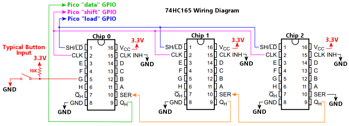
Configures one or more daisy chains of 74HC165 input shift register chips. These ports can be used to add digital input ports to the Pico, which Pinscape can use as button inputs. These chips are inexpensive and easy to work with in circuit board designs.
These chips provide an extremely low-latency input interface that's expandable to a large number of inputs. The Pinscape software scans these ports using the Pico's dedicated programmable I/O hardware, which allows bit clocking at megahertz speeds, for read latencies of a few microseconds. These chips are essentially as fast as the Pico's native GPIO ports.
The 74HC165 ports don't have any internal pull-up or pull-down resistors, so if you're using the chip to read button switches, you have to provide your own pull-up or pull-down resistor on each port so that it has a definite input voltage when the button switch is open. Leaving a port free-floating without any pull-up or pull-down reference resistor will make the chip read random input levels on the port. If you're using an expansion board designed for Pinscape, it probably has the resistors built in; if you're designing your own boards, you should include suitable resistors in the design. The standard setup is to connect each 74HC165 port to a pull-up resistor, around 10K, that connects on the other end to 3.3V. Then connect one terminal of each switch to a 74HC165 port, and connect the other switch terminal to DC ground (GND or 0V). The 74HC165 port will read as LOW when you press the button, HIGH the rest of the time.
These chips are designed to be chained together in a daisy chain, one chip connecting to the next, with only one chip connected directly to the Pico. That allows multiple chips to be connected while only taking up the GPIOs needed to connect one chip. Pinscape allows you to set up multiple daisy chains, each chain having its own set of GPIO connections, but there's little reason to do this in most cases given that you can just add more chips as needed to a single chain. If you do set up multiple chains, configure the "74hc165" property as an array of objects, with one object per daisy chain.
The "74hc165" property in the JSON file must be enclosed in double-quotes, because it starts with a digit rather than a letter.
The Pico GPIO port number connected to the serial output pin on the chip, labeled QH on the TI data sheet, or Q7 on the NXP data sheet.
Note that the chip also has an inverted output, labeled
Connect this GPIO port to the to the QH or Q7 pin on the first chip on the daisy chain only. Unlike the "shift" and "load" GPIO ports, don't connect this GPIO to all of the chips on the chain. Connect it to the first chip only.
The QH (or Q7) ports are what form the daisy chain. Connect the second chip's QH serial input port to the first chip's Serial Out pin, which is labeled SER on the TI data sheets, or DS on the NXP data sheet. Connect the third chip's QH/Q7 to the second chip's SER/DS pin, and so on down the chain. The last pin's SER/DS pin should be connected to ground.
The Pico GPIO number port connected to the "load" pin on the chip. This is labeled SH/LD (Shift/Load) on TI data sheets, or /PL (Parallel Load) on NXP data sheets. Connect this port to the SH/LD pins on all of the chips in the chain.
Sets the polarity of the "load" pin that selects LOAD mode. (The "load" pin is labeled SH/LD on TI data sheets, or /PL on NXP data sheets.)
This type of chip has two modes, selected by the "load" pin: SHIFT mode, where the chip transfers the contents of the shift register to the host microcontroller, and LOAD mode, where the chip loads the shift register from the 8 input pins. On the original 74HC165 chips, the mode selection is controlled by the SH/LD pin, and taking the pin LOW puts the chip in LOAD mode.
The reason this property is provided is that there are some other types of serial-input chips that are almost identical to the 74HC165, except that they invert the logic of their version of the SH/LD pin, so that setting the pin to "high" enables load mode. This software option is designed to give the Pinscape 74HC165 code enough flexibility to also work with this almost-identical chips, so that we don't need to create a whole separate chip type in the software to deal with this one small difference. If you're using one of those almost-but-not-quite-74HC165 chips, set loadPolarity according to the sense of your chip's version of the load/shift pin. If LOAD mode is activated by taking the pin HIGH, set this property to true; otherwise set it to false.
The number of chips making up the daisy chain. This is required so that the software knows how many ports to read on each input cycle.
The Pico GPIO port number connected to the "shift clock" pin on the chip, labeled CLK (Serial Clock) on the TI data sheet, or CP (Clock Input) on the NXP data sheet. Connect this port to the CLK pins on all of the chips in the chain.
Sets the clock rate, in Hz, for the shift clock signal sent to the daisy chain on the CLK pin (labeled CP on the NXP data sheet). This determines the data bit rate used to transfer port ON/OFF data from the chips to the Pico. The default is 6000000 (6 MHz), which is a conservative default based on the limits specified in the TI SN74HC165 data sheet. Higher frequencies allow faster polling of the input ports, but the chips will only operate correctly up to a limit, and higher frequencies are also more vulnerable to electronic noise in the wiring. That makes the usable limit vary by setup, so Pinscape makes it an adjustable parameter. The optimal setting is the highest value that works reliably with your setup. The default is conservative enough that it should work for most setups, but should also be fast enough for most needs (at 6 MHz, it takes 12us to transfer the data for 64 ports).
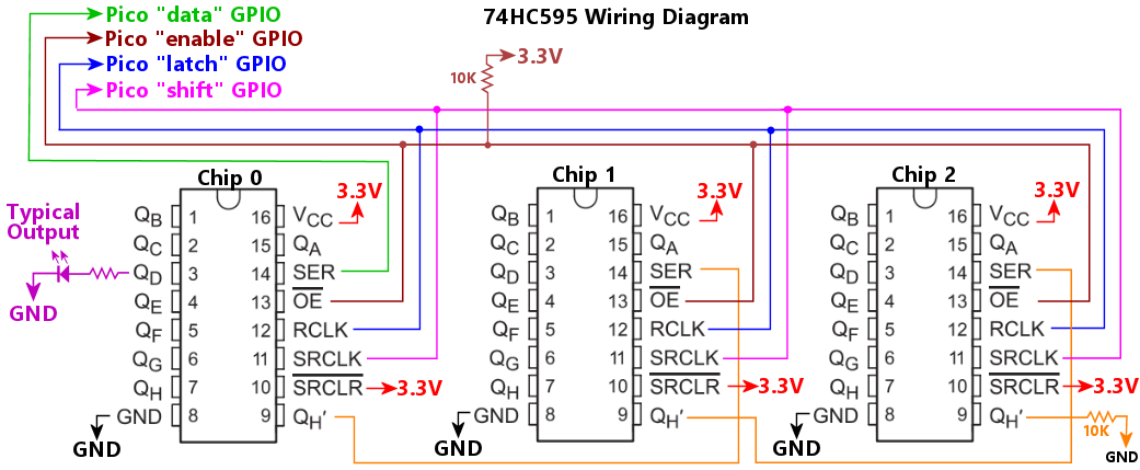
Configures one or more daisy chains of 74HC595 output shift register chips. These ports can be used to add digital (on/off) or PWM output ports to the Pico, which Pinscape can use as feedback device outputs. These chips are widely available, inexpensive, and easy to work with in circuit board designs, so they're an attractive option if you're designing custom hardware.
These chips are designed to be chained together in a daisy chain, one chip connecting to the next, with only one chip connected directly to the Pico. That allows multiple chips to be connected while only taking up the GPIOs needed to connect one chip. Pinscape allows you to set up multiple daisy chains, each chain having its own set of GPIO connections, but there's little reason to do this in most cases given that you can just add more chips as needed to a single chain. If you do set up multiple chains, configure the "74hc595" property as an array of objects, with one object per daisy chain.
At the hardware level, the 74HC595 is a "digital" output port chip: all of the ports are simple ON/OFF switches. However, Pinscape Pico can optionally provide PWM brightness control through these chips, by rapidly switching the ports on and off to modulate their duty cycle proportionally to the desired brightness level, across the 256-step brightness scale that DOF uses. These aren't ideal chips for PWM ports, because the rapid switching requires a very high data rate to the chip, in the megahertz range. This might not work reliably (or might even not work at all) with some circuit boards, since such high signal rates are vulnerable to electrical noise and interference, so they require careful wiring to work reliably. The best bet is to integrate the Pico and the 74HC595 chips into a single circuit board, placing all parts close together with short circuit traces. Setups with external cabling between the chips and the Pico might be less reliable. In addition, even with megahertz data rates, these chips can still only achieve relatively modest PWM refresh rates, in the hundreds of Hertz, depending on how many chips are on the daisy chain: 1-2 chips will run at about 1000 Hz, and 7-8 chips will reduce the rate to around 240 Hz. (It might seem strange that the PWM rates are so sluggish when we were just talking about megahertz data rates, but there's a good reason. The PWM rate is a small fraction of the data clock rate, because the Pico has to switch the ports on and off many times during each PWM cycle. This requires sending many data bits to the chip on each PWM cycle. The overall PWM cycle time reflects the time it takes to send all of these bits over the course of a cycle.) 200+ Hz is plenty fast to eliminate any trace of flicker with LEDs, but it might be too slow for inductive devices like motors and solenoids, since some of those are prone to audible buzzing or whining when run at such low PWM frequencies. If you do run into any noise problems driving motors or solenoids with these chips, you might have to move those devices to some other output chip that can achieve higher PWM rates, such as TLC59116, or a Pico GPIO port.
The "74hc595" property in the JSON file must be enclosed in double-quotes, because it starts with a digit rather than a letter.
Wiring notes:
The Pico GPIO port number connected to the DS (serial data) pin on the first chip on the daisy chain only.
Unlike the "shift", "latch", and "enable" GPIO ports, this GPIO is not connected to all of the chips on the daisy chain. Instead, this GPIO connects only to the first chip on the chain. The other chips on the chain still need data port inputs, but each chip gets its input from its nearest neighbor - that's what actually forms the daisy chain, as each chip passes its data output to the next chip's data input. The second chip's "serial in" DS port connects to the first chip's "serial out" port, labeled Q7S on the data sheet. The third chip's DS connects to the second chip's Q7S. And so on down the chain.
For the last chip on the daisy chain, you can leave the Q7S serial data out pin unconnected, or you can connect it to ground through a high-value resistor, perhaps 100K. Connecting it to ground in this fashion might help reduce its propensity to like an antenna, broadcasting radio-frequency noise.
The Pico GPIO port number connected to the OE (output enable) pin on the chips.
Alternatively, this can be an object, using the same syntax as outputs[].device. This allows you to connect the OE pin to a GPIO extender such as a PCA9555, saving a GPIO port on the Pico.
Connect the Pico port you select to the OE pins on all of the chips in the chain. Also connect the port to 3.3V through a pull-up resistor, typically 10K. The pull-up resistor ensures that the OE signal is pulled high, disabling all of the 74HC595 output ports, during the brief time after power-up when the Pico's GPIO pins are in their initial high-impedance state. Without the pull-up resistor, the OE signal would be left floating immediately after power-up, which might cause the 74HC595 ports to randomly activate, firing connected devices briefly.
The Pinscape software uses the OE signal to ensure glitch-free startup. 74HC595 chips power up with random values in the shift register, so it's important to disable all of the 74HC595 output ports immediately at power-up, until the Pico has a chance to set all of the ports to OFF. The Pinscape software initializes all of the ports to OFF very soon after a reset, but there's a brief time window after power-up before this initialization step occurs. If the 74HC595 ports are enabled during this brief time window, attached devices can be randomly triggered, due to the random initial ON/OFF values in the shift register. Pinscape holds the OE line high until it completes the initialization step, which ensures that the random values in the shift register aren't ever visible on the output pins, in turn preventing any random device activation. Connecting OE to both a Pico port and a pull-up resistor ensures that the OE line is held high from the very instant power is applied.
The OE connection is optional. You can simplify your hardware design by simply connecting the OE pin directly to GND (0V), which permanently enables the output ports. But doing this might result in startup glitches, because it will enable the 74HC595 output ports immediately after power-on, when the shift register contains random on/off values. Any shift register positions that are randomly ON will cause the associated ports to turn ON, firing the attached devices. As soon as the Pinscape software starts running, it will turn all of the ports off again, so the initial random device activation will only last for a fraction of a second, which is why we call it a "startup glitch". This might not be a problem at all for some setups, such as when all of the output devices are LEDs; a brief random LED flash at startup probably won't bother anyone. Glitches are more objectionable when noise-making devices like solenoids or motors are involved, since it can be alarming to have a bunch of solenoids all fire at the same time.
The Pico GPIO port number connected to the latch/transfer pin on the chips, which is labeled STCP on some data sheets, RCLK on others. Connect this to the STCP/RCLK pins on all of the chips in the chain. The GPIO port must be the next higher GPIO port after the 'shift' port; for example, if 'shift' is on GPIO 15, 'latch' must be on GPIO 16.
The number of chips in the daisy chain. This is required so that the software knows how many ports to update on each output cycle.
Sets the operating mode for the chain: true configures the chain in PWM mode, false (the default) configures it in digital mode. In digital mode, the outputs are simple on/off switches. When used as DOF ports, any non-zero DOF "brightness" setting switches the port ON, and a zero DOF level switches the port OFF. In PWM mode, the outputs have full DOF brightness control, with the same 0-255 range that DOF uses.
The Pico GPIO port number connected to the the shift clock pin on the chip, labeled SHCP in some data sheets and SRCLK in others. Connect this to the SHCP pins on all of the chips in the chain.
Sets the clock rate, in Hz, for the shift clock (SHCP/SRCLK) signal sent to the daisy chain. This determines the data bit rate used to transfer port ON/OFF data from the Pico to the chips. The default is 4000000 (4 MHz), which is a conservative default based on the limits specified in the TI SN74HC595 data sheet. Higher frequencies allow faster updates of the output ports, but the chips won't function properly if the frequency is too high for them to process, so the optimal frequency is the highest value that works reliably. That will vary from one setup to the next, since many factors affect the maximum usable speed, such as the specific type of 74HC595 chips you're using (there are several variants on the market) and the physical layout of your circuits boards and cabling. The default should be fine for most setups, but if you encounter any glitching on the outputs, you can try reducing the rate to see if that improves matters.
When operating the chip in digital mode (where the ports are purely ON/OFF switches with no brightness control), the clock speed doesn't need to be very fast; a setting as low as 100000 Hz should be fine. The speed is much more important when operating the chips in PWM mode, because it determine the PWM refresh cycle period, which must be at least 100 Hz to avoid visible flicker if you're using the chips to control lighting devices like LEDs. The default setting of 4000000 Hz yields a refresh rate around 240 Hz with an 8-chip daisy chain (and shorter daisy chains are proportionally faster), so it should be a good compromise between PWM refresh rate and signal integrity. If you find that outputs are flaky, you can try reducing the clock speed, but LED flicker might become noticeable if you go below about 1000000 Hz. You can also try increasing the clock rate if you want to take the PWM refresh rate higher, although I don't think there's much benefit to doing so. LED flicker should be fully gone at 200 Hz, so there's no need to go higher just for the sake of lighting devices. The main reason you might want to drive the PWM rate much higher than 200 Hz would be to address acoustic noise problems in inductive devices like solenoids and motors, and to do that, you generally have to raise the PWM rate to about 20 kHz, so that it's beyond the human hearing range. That's unfortunately not possible with these chips, because it would require a shift clock rate in the 300 MHz range, which is far beyond the documented limits of these chips even under the best conditions.
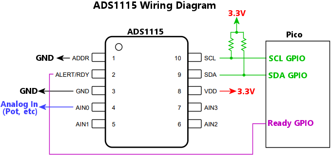
Configures one or more ADS1115 analog-to-digital converter (ADC) chips. If multiple ADS1115 chips are connected, use an array of this object type, one for each chip.
Why would you want to use an external ADC like ADS1115, when the Pico already has a built-in ADC of its own? Because the Pico's built-in ADC is mediocre at best. An external ADC might be preferable if you're using a potentiometer as your plunger position sensor, because the quality of the position readings from a potentiometer depends upon the quality of the ADC. The Pico's built-in ADC only has about 8 bits of digital resolution, so it can only distinguish a few hundred position increments - and even fewer after taking into account analog noise. That's not good enough for truly smooth animation in the pinball simulators. ADS1115 has 16-bit resolution, allowing for much finer increments of position readings, which can make for smoother animation and more consistent physics behavior in the simulators.
Wiring notes:
The 7-bit I2C address of the chip. The chip's address is configured by the wiring on its ADDR pin, which can select among four addresses (0x48, 0x49, 0x4A, 0x4B). Set this property according to the ADDR pin wiring.
The input channel number or numbers you're using on the chip. The ADS1115 has four input pins, AIN0 to AIN3, that can be connected to up to four separate analog inputs that you want to measure. This property lets you tell Pinscape how these map to "logical" channels, which are the channels that Pinscape actually reads. If you only need to measure one input voltage with the chip, you only need to configure one logical channel.
The simplest way to connect voltage inputs to the ADS1115 is as "single-ended" inputs, where each AINx pin measures a positive voltage relative to GND. This configuration is suitable for the most common virtual pin cab use case, which is measuring the voltage on a potentiometer, such as a plunger position sensor or a joystick. To use this configuration, simply connect the analog voltage source you wish to measure, such as the wiper pin from a potentiometer, to one of the AINx pins. List the AINx pin number in the channel property. For example, if the pot wiper is connected to AIN3, use channel: 3 to set up a logical channel reading from pin AIN3.

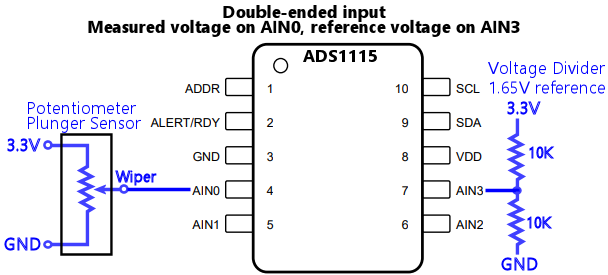
The ADS1115 also allows "double-ended" inputs, where you use two AINx pins to measure the voltage differential between two signals. This lets you use a positive voltage as the reference point, instead of GND. This is especially useful if you have a separate analog power supply with a more precise voltage regulator than the digital 3.3V supply, or if the voltage being measured only varies over a small portion of the 3.3V range. The reference Pinscape Pico expansion boards take advantage of the differential capability by providing a voltage divider to create a 1.65V voltage reference on AIN3, as shown in the diagram below; use channel: "AIN0/AIN3" for this wiring arrangement. The benefit of this setup is that you can use a smaller amplifier range setting in the ADS1115 input stage, since the potentiometer reading can only vary from -1.65V to +1.65V relative to the 1.65V reference on the divider. This effectively adds one bit of resolution to the digitized result.
The ADS1115 only allows double-ended inputs on certain channel pairings, as shown below.
| Value | Channel configuration |
|---|---|
| 0, "0", or "AIN0" | Single-ended, AIN0 (referenced to GND) |
| 1, "1", or "AIN1" | Single-ended, AIN1 (referenced to GND) |
| 2, "2", or "AIN2" | Single-ended, AIN2 (referenced to GND) |
| 3, "3", or "AIN3" | Single-ended, AIN3 (referenced to GND) |
| "0/1" or "AIN0/AIN1" | Double-ended, positive=AIN0, negative=AIN1 |
| "0/3" or "AIN0/AIN3" | Double-ended, positive=AIN0, negative=AIN3 |
| "1/3" or "AIN1/AIN3" | Double-ended, positive=AIN1, negative=AIN3 |
| "2/3" or "AIN2/AIN3" | Double-ended, positive=AIN2, negative=AIN3 |
You can set up multiple logical channels, by using an array for the channel property. And you can freely mix and match single-ended and double-ended inputs. For example, channel: ["0/1", 2] sets up two logical channels, one that reads a double-ended input on pins AIN0/AIN1, and a second that reads a single-ended input on AIN2.
The ADS1115 can physically only sample one channel at a time, so if you configure multiple channels, the chip has to cycle through the channels in a round-robin rotation. This slows down the sampling rate for each channel by a factor of N (the number of channels configured), because the chip has to complete an entire sampling period for each channel before moving on to the next. For time-critical devices like a plunger sensor, it's better to devote the whole ADS1115 chip to a single input so that the chip doesn't have to divide its time among other inputs. You can connect up to four ADS1115 chips to the Pico, so if you need multiple inputs and maximum speed per input, the best approach is to connect multiple ADS1115 chips.
The I2C bus number, 0 for I2C0 or 1 for I2C1, where the chip is connected.
The GPIO port connected to the chip's ALERT/RDY pin. You can omit this if the pin isn't connected to a Pico port. It's preferable to connect the pin to the Pico, because it allows more efficient use of the I2C bus by letting the Pico know when a new sample is ready without any unnecessary I2C polling.
The sampling rate, in samples per second. This determines the rate at which the chip produces samples for the Pico to read across the I2C connection; internally, the chip collects samples at a higher rate, and averages them over the I2C reporting period, so longer periods improve the sampling quality by averaging out noise in the signal. The chip only supports certain fixed rates: 8, 16, 32, 64, 128, 250, 474, and 860 samples per second. You can set sampleRate to any value, but the actual rate will be set to the closest of those allowed rates. The default is 860.
Sets the full-scale voltage range for the ADS1115 inputs. The ADS1115 has an internal amplifier that can be configured to scale the voltage input to different ranges. This is useful because it allows you to adjust the voltage range that the chip measures to be as close as possible to the actual physical voltage range that the input will use. The chip can be configured for the following ranges:
| Value | Range |
|---|---|
| 0.256 | +/- 0.256V |
| 0.512 | +/- 0.512V |
| 1.024 | +/- 1.024V |
| 2.048 | +/- 2.048V |
| 4.096 | +/- 4.096V |
| 6.144 | +/- 6.144V |
You can set this to any numeric value, but the chip can only accept the values listed above, so Pinscape will choose the closest match (the one with the smallest numeric difference from the value you specify) if you enter a value not listed.
The default is 4.096, which is suitable for most Pico applications, where the analog voltage you're measuring is in the same range as the Pico's GPIO port logical range, 0V to 3.3V. If you're connecting a device that uses a wider or smaller range of voltages, you can improve the resolution of the measurements by changing the range setting.
It won't damage the chip if the actual voltage input exceeds the full-scale range. The chip physically tolerates voltages on the AINx inputs from 0V to slightly over the supply voltage, usually 3.3V, regardless of the amplifier range setting. A voltage that exceeds the amplifier range setting simply clips to the maximum digital readout value (+32767).
Important: The voltageRange setting only sets the internal range on the input amplifier stage within the chip. It doesn't make it safe for the input voltage at the AINx pin to exceed the 0 to 3.3V supply voltage range. Never apply a voltage below 0V or above 3.3V to an AINx pin. Refer to the Absolute Maximum Ratings section in the ADS1115 data sheet for details on the safe operating ranges.
Configures an AEDR-8300 linear quadrature encoder chip. These chips can be used as plunger position sensors. Refer to the setup instructions in the Pinscape Build Guide.
The Pico GPIO port number connected to the chip's channel "A" pin.
The Pico GPIO port number connected to the chip's channel "B" pin.
Defines the logical button inputs, which map physical and virtual button inputs to actions, such as sending keystrokes to the PC. Each entry in this list is an object that defines one logical button. Each logical button definition has a source, which specifies the physical or virtual input that triggers the action, and an action, which specifies what happens when you press the source button. Each logical button can also have a "type", which specifies how changes to the physical input are interpreted. The standard type is "pushbutton", which is an ordinary momentary switch that carries out its action as long as you're physically pressing the button, and stops as soon as you release it. Other types include "hold" buttons, which only carry out their action after being held down for a defined interval; "pulse" buttons, which only carry out their action once when pushed, rather than continuously while being held down; "toggle" buttons, which switch between OFF and ON each time they're pushed, rather than staying on only while being held down; and "shift" buttons, which let you assign multiple meanings to other buttons, analogous to the keys like SHIFT, CTRL, and ALT on a PC keyboard.
Buttons are defined using two main abstractions:
Each buttons[] entry's main job is to connect a source and an action. When the source records an activation (pressing the physical button, receiving the IR command, crossing an accelerometer threshold), the action is carried out.
The same source can be used more than once (that is, in more than one buttons[] array entry). This lets you map a single physical input to multiple actions to be carried out, such as sending both a keyboard key press and a joystick button press to the PC whenever the button is pressed. Macros can also be used to carry out multiple effects for each button press, with the additional feature that macros can control the timing of the sub-actions.
This is an object that specifies the action that's triggered when the logical button is activated by its input source.
This specifies which type of action to take when the button is activated.
| Type | Description |
|---|---|
| "key" | Keyboard key press |
| "media" | Media controller key press |
| "gamepad" | Gamepad button press |
| "xInput" | XBox controller button press |
| "openPinDev" | Open Pinball Device button press |
| "reset" | Reset the Pico |
| "nightmode" | Toggle Night Mode |
| "plungercal" | Start plunger calibration |
| "IR" | Send an IR command on the IR transmitter |
| "macro" | Execute a macro |
| "none" | Do nothing |
Sets up the button to transmit a remote control command through the IR emitter when pressed.
If set to true, the IR command is sent repeatedly as long as the logical button is activated. If false (the default), the command is only sent once when the logical button is pressed, no longer how long the button remains activated.
The IR command code to send when the button is pressed, expressed as a string in the Pinscape universal IR code format. The easiest way to determine the right code to use for a particular button press is to use the Pinscape Config Tool's IR & TV ON window, which displays codes as they're received on the sensor. Open the window and press the remote control button whose code you want to determine, and it should appear in the list of commands received. Now simply copy the code from that list into the type string here.
Sets up the button to act as a gamepad button on the PC. Activating the logical button presses the associated gamepad button.
The gamepad button number to press when the logical button is activated, 1 to 32, or a string from the list below.
| String Value | Description |
|---|---|
| hat-down | Hat switch "down" (south) button |
| hat-left | Hat switch "left" (west) button |
| hat-right | Hat switch "right" (east) button |
| hat-up | Hat switch "up" (north) button |
This sets up the button to act as a keyboard key on the PC. When the button is activated, Pinscape sends the designated key press, and keeps sending it as long as the button remains activated.
To use keyboard actions, make sure that the USB keyboard device is enabled via the keyboard.enable property.
A type="key" action is a very literal emulation of a physical USB keyboard key press, which means that it can send any one key, but only the one. If you want send a combination of key presses involving modifier keys, such as Ctrl+A or Shift+Ctrl+End, you need a macro.
Specifies the keyboard key to send when the button is pressed. This can be a "usage number" from the USB HID keyboard page, from 1 to 255, or it can be a string giving the name of the key, from the set listed below.
Alternatively, the key can be a "chord", which is a combination of keys with modifiers such as Ctrl, Shift, and Alt. Chords are written using the Microsoft convention, as in "Ctrl+Shift+F1" to mean holding down the Ctrl and Shift keys while pressing the F1 key. When you define a chord in this notation, the software internally converts the "key" action into a "macro" action, and automatically programs the macro with a series of "key" steps matching the keys you list in the chord, with all of the steps starting as soon as you press the source button, and all of the steps remaining in effect until you release the source button. So the macro steps are set to { start: 0, duration: "hold" }.
| Key name | USB usage | Description |
|---|---|---|
| "a" | 0x04 | Keyboard a and A |
| "b" | 0x05 | Keyboard b and B |
| "c" | 0x06 | Keyboard c and C |
| "d" | 0x07 | Keyboard d and D |
| "e" | 0x08 | Keyboard e and E |
| "f" | 0x09 | Keyboard f and F |
| "g" | 0x0A | Keyboard g and G |
| "h" | 0x0B | Keyboard h and H |
| "i" | 0x0C | Keyboard i and I |
| "j" | 0x0D | Keyboard j and J |
| "k" | 0x0E | Keyboard k and K |
| "l" | 0x0F | Keyboard l and L |
| "m" | 0x10 | Keyboard m and M |
| "n" | 0x11 | Keyboard n and N |
| "o" | 0x12 | Keyboard o and O |
| "p" | 0x13 | Keyboard p and P |
| "q" | 0x14 | Keyboard q and Q |
| "r" | 0x15 | Keyboard r and R |
| "s" | 0x16 | Keyboard s and S |
| "t" | 0x17 | Keyboard t and T |
| "u" | 0x18 | Keyboard u and U |
| "v" | 0x19 | Keyboard v and V |
| "w" | 0x1A | Keyboard w and W |
| "x" | 0x1B | Keyboard x and X |
| "y" | 0x1C | Keyboard y and Y |
| "z" | 0x1D | Keyboard z and Z |
| "1" | 0x1E | Keyboard 1 and ! |
| "!" | 0x1E | Keyboard 1 and ! |
| "2" | 0x1F | Keyboard 2 and @ |
| "@" | 0x1F | Keyboard 2 and @ |
| "3" | 0x20 | Keyboard 3 and # |
| "#" | 0x20 | Keyboard 3 and # |
| "4" | 0x21 | Keyboard 4 and $ |
| "$" | 0x21 | Keyboard 4 and $ |
| "5" | 0x22 | Keyboard 5 and % |
| "%" | 0x22 | Keyboard 5 and % |
| "6" | 0x23 | Keyboard 6 and ^ |
| "^" | 0x23 | Keyboard 6 and ^ |
| "7" | 0x24 | Keyboard 7 and & |
| "&" | 0x24 | Keyboard 7 and & |
| "8" | 0x25 | Keyboard 8 and * |
| "*" | 0x25 | Keyboard 8 and * |
| "9" | 0x26 | Keyboard 9 and ( |
| "(" | 0x26 | Keyboard 9 and ( |
| "0" | 0x27 | Keyboard 0 and ) |
| ")" | 0x27 | Keyboard 0 and ) |
| "return" | 0x28 | Keyboard Return (ENTER) |
| "enter" | 0x28 | Keyboard Return (ENTER) |
| "esc" | 0x29 | Keyboard ESCAPE |
| "escape" | 0x29 | Keyboard ESCAPE |
| "backspace" | 0x2A | Keyboard DELETE (Backspace) |
| "bksp" | 0x2A | Keyboard DELETE (Backspace) |
| "tab" | 0x2B | Keyboard Tab |
| "space" | 0x2C | Keyboard Spacebar |
| "spacebar" | 0x2C | Keyboard Spacebar |
| "-" | 0x2D | Keyboard - and (underscore) |
| "_" | 0x2D | Keyboard - and (underscore) |
| "hyphen" | 0x2D | Keyboard - and (underscore) |
| "minus" | 0x2D | Keyboard - and (underscore) |
| "=" | 0x2E | Keyboard = and + |
| "+" | 0x2E | Keyboard = and + |
| "equals" | 0x2E | Keyboard = and + |
| "[" | 0x2F | Keyboard [ and { |
| "{" | 0x2F | Keyboard [ and { |
| "lbrack" | 0x2F | Keyboard [ and { |
| "lbrace" | 0x2F | Keyboard [ and { |
| "]" | 0x30 | Keyboard ] and } |
| "}" | 0x30 | Keyboard ] and } |
| "rbrack" | 0x30 | Keyboard ] and } |
| "rbrace" | 0x30 | Keyboard ] and } |
| "\\" | 0x31 | Keyboard \ and | |
| "||" | 0x31 | Keyboard \ and | |
| "backslash" | 0x31 | Keyboard \ and | |
| ";" | 0x33 | Keyboard ; and : |
| ":" | 0x33 | Keyboard ; and : |
| "semicolon" | 0x33 | Keyboard ; and : |
| "colon" | 0x33 | Keyboard ; and : |
| "'" | 0x34 | Keyboard ' and " |
| "\"" | 0x34 | Keyboard ' and " |
| "," | x36 | Keyboard , and < |
| "<" | 0x36 | Keyboard , and < |
| "comma" | x36 | Keyboard , and < |
| "." | 0x37 | Keyboard . and > |
| ">" | 0x37 | Keyboard . and > |
| "period" | 0x37 | Keyboard . and > |
| "dot" | 0x37 | Keyboard . and > |
| "/" | 0x38 | Keyboard / and ? |
| "?" | 0x38 | Keyboard / and ? |
| "slash" | 0x38 | Keyboard / and ? |
| "caps lock" | 0x39 | Keyboard Caps Lock |
| "capslock" | 0x39 | Keyboard Caps Lock |
| "f1" | 0x3A | Keyboard F1 |
| "f2" | 0x3B | Keyboard F2 |
| "f3" | 0x3C | Keyboard F3 |
| "f4" | 0x3D | Keyboard F4 |
| "f5" | 0x3E | Keyboard F5 |
| "f6" | 0x3F | Keyboard F6 |
| "f7" | 0x40 | Keyboard F7 |
| "f8" | 0x41 | Keyboard F8 |
| "f9" | 0x42 | Keyboard F9 |
| "f10" | 0x43 | Keyboard F10 |
| "f11" | 0x44 | Keyboard F11 |
| "f12" | 0x45 | Keyboard F12 |
| "print screen" | 0x46 | Keyboard PrintScreen |
| "printscreen" | 0x46 | Keyboard PrintScreen |
| "prntscrn" | 0x46 | Keyboard PrintScreen |
| "prtscr" | 0x46 | Keyboard PrintScreen |
| "scrolllock" | 0x47 | Keyboard Scroll Lock |
| "scroll lock" | 0x47 | Keyboard Scroll Lock |
| "pause" | 0x48 | Keyboard Pause |
| "ins" | 0x49 | Keyboard Insert |
| "insert" | 0x49 | Keyboard Insert |
| "home" | 0x4A | Keyboard Home |
| "page up" | 0x4B | Keyboard PageUp |
| "pageup" | 0x4B | Keyboard PageUp |
| "pgup" | 0x4B | Keyboard PageUp |
| "del" | 0x4C | Keyboard Delete Forward |
| "delete" | 0x4C | Keyboard Delete Forward |
| "end" | 0x4D | Keyboard End |
| "page down" | 0x4E | Keyboard PageDown |
| "pagedown" | 0x4E | Keyboard PageDown |
| "pagedn" | 0x4E | Keyboard PageDown |
| "pgdn" | 0x4E | Keyboard PageDown |
| "right" | 0x4F | Keyboard RightArrow |
| "right arrow" | 0x4F | Keyboard RightArrow |
| "left" | 0x50 | Keyboard LeftArrow |
| "left arrow" | 0x50 | Keyboard LeftArrow |
| "down" | 0x51 | Keyboard DownArrow |
| "down arrow" | 0x51 | Keyboard DownArrow |
| "up" | 0x52 | Keyboard UpArrow |
| "up arrow" | 0x52 | Keyboard UpArrow |
| "numlock" | 0x53 | Keypad Num Lock and Clear |
| "num lock" | 0x53 | Keypad Num Lock and Clear |
| "clear" | 0x53 | Keypad Num Lock and Clear |
| "keypad /" | 0x54 | Keypad / |
| "keypad *" | 0x55 | Keypad * |
| "keypad -" | 0x56 | Keypad - |
| "keypad +" | 0x57 | Keypad + |
| "keypad enter" | 0x58 | Keypad ENTER |
| "keypad 1" | 0x59 | Keypad 1 and End |
| "keypad 2" | 0x5A | Keypad 2 and Down Arrow |
| "keypad 3" | 0x5B | Keypad 3 and PageDn |
| "keypad 4" | 0x5C | Keypad 4 and Left Arrow |
| "keypad 5" | 0x5D | Keypad 5 |
| "keypad 6" | 0x5E | Keypad 6 and Right Arrow |
| "keypad 7" | 0x5F | Keypad 7 and Home |
| "keypad 8" | 0x60 | Keypad 8 and Up Arrow |
| "keypad 9" | 0x61 | Keypad 9 and PageUp |
| "keypad 0" | 0x62 | Keypad 0 and Insert |
| "keypad ." | 0x63 | Keypad . and Delete |
| "application" | 0x65 | Keyboard Application |
| "power" | 0x66 | Keyboard Power |
| "keypad =" | 0x67 | Keypad = |
| "f13" | 0x68 | Keyboard F13 |
| "f14" | 0x69 | Keyboard F14 |
| "f15" | 0x6A | Keyboard F15 |
| "f16" | 0x6B | Keyboard F16 |
| "f17" | 0x6C | Keyboard F17 |
| "f18" | 0x6D | Keyboard F18 |
| "f19" | 0x6E | Keyboard F19 |
| "f20" | 0x6F | Keyboard F20 |
| "f21" | 0x70 | Keyboard F21 |
| "f22" | 0x71 | Keyboard F22 |
| "f23" | 0x72 | Keyboard F23 |
| "f24" | 0x73 | Keyboard F24 |
| "execute" | 0x74 | Keyboard Execute |
| "help" | 0x75 | Keyboard Help |
| "menu" | 0x76 | Keyboard Menu |
| "select" | 0x77 | Keyboard Select |
| "stop" | 0x78 | Keyboard Stop |
| "again" | 0x79 | Keyboard Again |
| "undo" | 0x7A | Keyboard Undo |
| "cut" | 0x7B | Keyboard Cut |
| "copy" | 0x7C | Keyboard Copy |
| "paste" | 0x7D | Keyboard Paste |
| "find" | 0x7E | Keyboard Find |
| "mute" | 0x7F | Keyboard Mute |
| "volup" | 0x80 | Keyboard Volume Up |
| "voldown" | 0x81 | Keyboard Volume Down |
| "voldn" | 0x81 | Keyboard Volume Down |
| "keypad ," | 0x85 | Keypad Comma |
| "keypad comma" | 0x85 | Keypad Comma |
| "keypad 00" | 0xB0 | Keypad 00 |
| "keypad 000" | 0xB1 | Keypad 000 |
| "ctrl" | 0xE0 | Keyboard LeftControl |
| "left ctrl" | 0xE0 | Keyboard LeftControl |
| "left control" | 0xE0 | Keyboard LeftControl |
| "shift" | 0xE1 | Keyboard LeftShift |
| "left shift" | 0xE1 | Keyboard LeftShift |
| "alt" | 0xE2 | Keyboard LeftAlt |
| "left alt" | 0xE2 | Keyboard LeftAlt |
| "gui" | 0xE3 | Keyboard Left GUI |
| "left gui" | 0xE3 | Keyboard Left GUI |
| "right ctrl" | 0xE4 | Keyboard RightControl |
| "right control" | 0xE4 | Keyboard RightControl |
| "right shift" | 0xE5 | Keyboard RightShift |
| "right alt" | 0xE6 | Keyboard RightAlt |
| "right gui" | 0xE7 | Keyboard Right GUI |
This sets up a macro button, which performs a series of timed actions when activated.
A macro can carry out any sequence of other basic actions, with the exception that it can't invoke another macro. This allows for all sorts of complex actions, such as pressing chords of keyboard keys (Ctrl+Shift+A, say), typing in a sequence of keystrokes to enter a command, pushing a joystick button and a keyboard key at the same time, or entering a series of joystick button presses.
The macro is defined as a series of steps to perform. Each step has a starting time relative to the previous step's starting time. This can be zero, in which case the step starts at the same time as the previous step. Each step also has a duration, which specifies how long the action goes on; for example, for a key press action, this specifies how long the key is held down.
A macro can be set to repeat its series of steps as long as the physical button is held down, or to just execute it once and then stop, even if the user continues to press the button indefinitely. Similarly, you can specify whether the macro runs to completion once started, even if the user doesn't keep holding down the button long enough to complete the macro, or if the macro stops in the middle of what it's doing when the user releases the button.
If set to true (the default), the macro will start over at the beginning if the button is still being held down after the last step finishes. If set to false, the macro only runs once, stopping after the last step even if the button is still being held down.
If set to true (the default), the macro runs through all of its steps every time the button is pressed, even if the button isn't held down as long as it takes to finish running through the steps. If set to false, the macro stops as soon as the button is released, even if there are still more steps that haven't been completed yet.
An array of objects giving the list of action steps to carry out when the button is pressed. Each step lists one action, with a starting time and a duration. Each step's action is an object with exactly the same properties as the main "action" property for a button, so in effect, a macro carries out the equivalent of a series of timed button presses. But the "buttons" being pressed don't have to exist outside of the macro, since the macro contains the entire definition of each action.
The action to perform. This is the same sort of action object that you can define for a button in its "action" property, with all of the same properties, except that it can't contain another macro action.
The duration of the step, in milliseconds, or the special string value "hold". This is the amount of time that the step's action remains activated. A step can remain activated even while later steps are started; new steps don't have to wait for earlier steps to finish.
If this is set to "hold", it means that the step remains in effect until the button that activated the macro is released. This makes it easy to define a macro that expresses a "key chord" such as Ctrl+Alt+X, by letting you program the macro to hold all three key actions as long as the button is being pressed.
The starting time of the step, as the number of milliseconds to wait after the start of the previous step. If this is zero (the default), this step starts simultaneously with the previous step. Note that the reference point is the starting time of the prior step, which lets you start multiple steps at the same time - a new step doesn't have to wait until the prior step finishes.
This sets up the button to act as a "media controller" key on the PC. These are essentially just an extended set of keyboard keys associated with media functions, like "Play" and "Pause", which appear on some keyboards as an extra row of keys above the function keys.
To use media key actions, make sure that the USB keyboard device is enabled via the keyboard.enable property.
Specifies the media key to send when the button is pressed. This is a string naming one of the special media keys that Pinscape can send.
| Key name | Description |
|---|---|
| "mute" | Mute audio |
| "volUp" | Audio volume up |
| "volDn" | Audio volume down |
| "next" | Skip to next media track |
| "prev" | Skip to previous media track |
| "stop" | Stop media playback |
| "play" | Start media playback |
| "eject" | Eject media (note: Windows ignores this key) |
Sets up the button as a Night Mode control. Pressing the button toggles the current Night mode setting.
This sets up a virtual button that accepts input but doesn't perform any action.
This sets up the button to send input through the Open Pinball Device interface.
To use this type of button mapping, the Open Pinball Device HID interface must be enabled via the openPinballDevice.enabled property.
Sets the Open Pinball Device virtual button to activate when this physical button is pressed.
The Open Pinball Device interface provides two kinds of buttons: a set of 32 "generic" numbered buttons, identified simply as button numbers 1 through 32; and a collection of pre-defined, named "pinball" buttons, with specific assigned functions that map to the standard functions that most of the PC pinball simulators use, such as "Start Game", "Launch Ball", "Left Flipper", and so on. The generic numbered buttons and the name pinball buttons are completely independent of one another, so this gives you a total of 59 assignable buttons: 32 generic numbered buttons plus the 27 named buttons.
To assign an action to a generic button, set button to a number from 1 to 32. These buttons are comparable to gamepad buttons, in that they don't have any pre-assigned meanings; they're just generic buttons that you can assign to a selected function in each PC program you're using. You have to go into each program's setup options or configuration file to map the numbered buttons to in-program functions. In Visual Pinball, for example, the generic Open Pinball Device buttons are treated exactly like joystick buttons, so you assign the VP function of generic button #1 by going into VP's Keys dialog and assigning one of the command keys to Joystick Button #1.
The pinball buttons are a separate set of virtual buttons that are pre-assigned to the common functions found in almost all of the pinball simulator programs. The nice thing about the pinball buttons is that the compatible simulators have built-in mappings for these, so you don't have to manually configure them in each simulator. Just assign a physical button to "start", and it'll automatically act as the Start button in every compatible simulator. To set up a pinball button action, use one of the strings shown below for the button value.
| Button name | Description |
|---|---|
| "start" | Start button (start a new game) |
| "exit" | Exit button (exit the simulator) |
| "coin 1" | Left coin slot |
| "coin 2" | Middle coin slot |
| "coin 3" | Right coin slot |
| "coin 4" | Fourth coin slot or bill acceptor |
| "extra ball" | Extra Ball/Buy-in button |
| "launch" | Launch Ball button and/or button-operated plunger |
| "fire" | Fire button (button on the top of the lock bar on many later Stern machines, for activating game-specific features) |
| "tilt bob" | Tilt bob switch (triggers a Tilt condition in the game; not for simulated nudge inputs) |
| "slam tilt" | Slam tilt switch (an additional type of tilt switch inside the coin door on many real machines) |
| "coin door" | Coin door open/closed position sensor switch |
| "service cancel" | Cancel/Exit button, part of the service/operator control panel located inside the coin door |
| "service down" | Down/Previous button, part of the service controls |
| "service up" | Up/Next button, part of the service controls |
| "service enter" | Enter/Select button, part of the service controls|
| "left magnasave" | Left MagnaSave button (an extra flipper-like button adjacent to the regular flipper button on some machines) |
| "right magnasave" | Right MagnaSave button |
| "left nudge" | Manual nudge input, simulating a nudge from the left side |
| "forward nudge" | Manual nudge input, simulating a nudge pushing forward |
| "right nudge" | Manual nudge input, simulating a nudge from the right side |
| "volume up" | Audio volume up (controls the audio volume within the simulator; doesn't usually affect the system-wide volume level) |
| "volume down" | Audio volume down |
| "left flipper" | Left flipper button |
| "left flipper 2" | Secondary left flipper switch, for stacked double switches used in many machines with upper |
| "right flipper" | Right flipper button |
| "right flipper 2" | Right secondary flipper switch, for stacked double switches |
The flipper buttons are split into "main" and "secondary" switches. These are designed to replicate the stacked leaf switches found in many mechanical pinball machines that feature upper and lower flippers. Both switches in the stack are operated by a single flipper button, so there's just one left button and one right button. Pushing the button part-way in closes the outer, "main" switch, which operates the main lower flipper on that side. Continuing to press the button further in eventually also closes the inner "secondary" switch in the stack, which operates the upper flipper on that side. Many mechanical pinballs are set up this way to allow players to operate the upper flipper on each side separately from the lower flipper, so that advanced players can hold a ball trapped in a lower flipper, while separately using the upper flipper to take a shot with another ball during multiball play. If your pin cab includes the stacked switches, you can set them up as separate physical button inputs, and map their actions to the corresponding main and secondary switches here.
Sets up the button to act as the plunger calibration mode control button. Pressing and holding the button for about two seconds activates calibration mode. Once calibration mode is initiated, the calibration runs for a set time (about 15 seconds) to gather data on the range of sensor readings over the plunger's mechanical travel distance. During this period, the user should pull the plunger all the way back, hold it briefly, release it, allow it to come to rest, and then repeat a few times. When the timed interval ends, the new calibration settings automatically go into effect.
Activating the button resets the Pico, optionally activating its Boot Loader mode.
The time the button must be held down, in milliseconds, before the reset occurs. Default is 2000ms (2 seconds).
Reset mode. "normal" resets the Pico and restarts the Pinscape firmware. "bootloader" puts the Pico into its native Boot Loader moder, where it presents itself as a virtual thumb drive for installing new firmware.
Sets up the button to act as an XBox controller button on the PC. Activating the logical button presses the associated XBox controller button.
The XBox controller button to press when the logical button is activated.
| Key name | Description |
|---|---|
| "up" | Direction pad UP button |
| "down" | Direction pad DOWN button |
| "left" | Direction pad LEFT button |
| "right" | Direction pad RIGHT button |
| "start" | START button |
| "back" | BACK button |
| "l3" | Left joystick click |
| "r3" | Right joystick click |
| "lb" | Left bumper button (back of controller) |
| "rb" | Right bumper button (back of controller) |
| "xbox" | XBOX button |
| "a" | A button |
| "b" | B button |
| "x" | X button |
| "y" | Y button |
Assigns the button a name, which you can use to refer to the button elsewhere in the configuration, such as in a computed output source (via the button() source type).
Marks the button as a USB wake-up button. If this is true, pressing the button while the PC is in sleep mode will send a USB wake-up signal to the PC. (The PC has to be configured to obey wake-up signals, which is usually the default on Windows PCs, but it might require modifying settings in your Windows power preferences and possibly the PC's BIOS.)
For a button with type="shift", this sets the bits that are added into the "global shift state" when the button is pressed.
For any other button type, this sets the value that the following formula must match each time the button is pressed for the button to activate:
global-shift-state AND shiftMask == shiftBits
See shiftMask for more details on how the shift bits and shift mask work together to determine how the button reacts to modifier buttons.
Sets the bits in the "global shift state" that the button is sensitive to.
When the button is pressed, Pinscape combines this button's shiftMask with the current global shift state using a bitwise AND. It then compares the result to the button's shiftBits. If the two values are equal, the press activates the button. Otherwise, the press is ignored.
This can be used to make a button sensitive to one or more modifier buttons, or to make it insensitive to all of the modifier buttons. The table below lists some basic formulas for how to set this up (in combination with shiftBits) to get different effects. For the examples in the table, let's say that we've set up the following shift buttons:
You can easily extend this idea to add as many more shift buttons as you need, up to a total of 32 of them. Just keep picking the next higher bit value for each added button: 0x0004, 0x0008, 0x0010, etc.
| Goal | shiftMask | shiftBits | Description |
|---|---|---|---|
| Ignores all shift buttons | 0 | 0 | This button always works the same way, regardless of which shift buttons are pressed. Since X AND 0 = 0 for all X, the result of shiftMask AND global-shift-state is always 0, so it always matches the zero in shiftBits, and the button always operates. |
| Operates when EXTRA BALL is not pressed | 0x0001 | 0x0000 | This button only takes effect when the EXTRA BALL shift button is NOT pressed. When EXTRA BALL is pressed, the global shift state contains EXTRA BALL's shiftBits bits, 0x0001, so shiftMask AND global-shift-state equals 0x0001. This is not equal to shiftBits, so the button ignores the press. When EXTRA BALL isn't pressed, the global shift state doesn't contain bit 0x0001, so shiftMask AND global-shift-state equals 0, which equals the shiftBits value, so the button activates. |
| Operates when EXTRA BALL is pressed | 0x0001 | 0x0001 |
This button only takes effect when the EXTRA BALL shift button is pressed.
When EXTRA BALL is pressed, the global shift state contains EXTRA BALL's
shiftBits bits, 0x0001, so shiftMask AND global-shift-state equals 0x0001.
This equals shiftBits, so the button activates.
When EXTRA BALL isn't pressed, the global shift state doesn't
contain bit 0x0001, so shiftMask AND global-shift-state equals 0, which
is unequal to shiftBits, so the button ignores the press.
Note that this button ignores the EXIT button state - it only pays attention to the EXTRA BALL state. |
| Operates when both EXTRA BALL and EXIT are pressed | 0x0003 | 0x0003 | This is how you create a chord analogous to Alt+Ctrl+X on a PC keyboard. This button takes effect only when BOTH shift keys are pressed. This works because the shiftMask contains the combination of shift bits for both of the modifier keys - 0x0001 OR 0x0002 = 0x0003. When we figure global-shift-state AND shiftMask, we get 0x0003 (the shiftBits value) only if the global shift state contains both of those bits, so the button only operates if both modifiers are pressed. |
| Operates when EXTRA BALL is pressed but not EXIT | 0x0003 | 0x0001 | This is the flip side of the EXTRA BALL + EXIT case above, setting the button so that it only operates when one of the modifier keys is pressed, but not both. shiftMask contains the bits for both of the shift keys, but shiftBits only contains the bits for EXTRA BALL, so the button will only operate when EXTRA BALL is pressed and EXIT is not. (To define a button that operates when EXIT is pressed but not EXTRA BALL, change shiftBits to 0x0002, the EXIT shift bits.) |
shiftMask has no effect for a button that's defined with type "shift". Shift buttons always mean one thing and always ignore other shift buttons.
Specifies the physical device port or data source that serves as the input for the logical button state. For a physical button, this is a hardware port connected to the button switch, such as a Pico GPIO port or a shift register input port. Buttons can also take their input from software sources, such as the plunger and nudge subsystems, or the IR remote control receiver.
"high" for a button whose port reads logic "1" when pressed, "low" for a port that reads logic "0". For physical inputs like GPIO ports and shift register inputs, a port is active-high if the switch connects the port to 3.3V when the button is pressed, and active-low if it connects to GND when pressed. The standard wiring is "active low", where one terminal of the switch is connected to the input port, and the other terminal is connected to GND. If this property is omitted, the default is active-low.
The source type. See the source types below for more details.
Sets the button's input source to a port on a 74HC165 chip. The 74HC165 is an input shift-register chip with 8 digital on/off input ports, which can be used as button inputs. Multiple 74HC165 chips can be daisy-chained, letting you add more input ports in groups of 8 as needed.
The daisy chain number. This is an index into the "74hc165:" array in the JSON configuration file, selecting which daisy chain this button is associated with. If you only have a single chain (which is almost always the case - it's rare to configure more than one), you can omit this, and the system will know you mean to use the one-and-only.
The chip number on the daisy chain. The first chip on the chain (the one attached directly to the Pico) is number 0, the second is number 1, and so on. If you include this, then you only have to give the port number relative to the chip; if you omit it, the port number is specified in terms of the whole chain.
Sets the debouncing "OFF" time for the switch input, in microseconds. This is the counterpart of debounceTimeOn, for when the switch transitions to OFF (releasing the button). Switches typically settle into the OFF state more quickly than into the ON state, so this can usually be set to a shorter value than the ON time. The default is 1000 microseconds (1 millisecond).
Sets the debouncing "ON" time for the switch input, in microseconds. Most physical switches "bounce" when switching between ON and OFF states, which means that the voltage level on the switch oscillates very rapidly for a brief time after the moment of contact. The brief instability in the signal can cause odd behavior in some host software reading the switch state; for example, if a button is mapped to keyboard input, the bounce effect might cause the key input to be repeated several times for a single button press. Debouncing refers to any sort of filtering that suppresses the oscillations after an on/off transition. Pinscape Pico debounces inputs by ignoring any further on/off changes for a brief time after each valid on/off change. This parameter sets the duration of that suppression time after an ON transition (from OFF to ON, when the button is pressed). The default value is 1500 microseconds (1.5 millisecond), which is long enough to suppress bounce in typical microswitches. If you experience any spurious input from a button, especially repeated inputs for a single button press, you can try increasing this. Longer values have the disadvantage that they limit the rate at which intentional fast taps can be processed.
Sets the debouncing low-pass filter time for falling edges, in microseconds. This is the minimum amount of time that the 74HC165 port must remain in the LOW state after a "falling edge" - a HIGH-to-LOW voltage transition on the port - before Pinscape will recognize the new LOW state. This is designed to filter out random electrical noise on the input, by requiring that the new LOW level remain in effect continuously for a minimum amount of time before it's treated as legitimate.
The FALL time applies to physical HIGH-to-LOW voltage transitions on the port, regardless of the active-high/low setting on the port.
Unlike the debounceTimeOn/Off "hold" times, the low-pass filter adds latency to input recognition, since the software won't recognize a physical button press until the low-pass filter time elapses. This value should therefore be kept as small as possible. The default is 0, which doesn't apply any low-pass filtering at all. For many switches, the latency-free debounceTimeOn/Off settings are all you need to eliminate switch bounce artifacts, but some switches have enough intrinsic noise that low-pass filtering is also required.
Sets the debouncing low-pass filter time for rising edges, in microseconds. This is the minimum amount of time that the 74HC165 port must remain in the HIGH state after a "rising edge" - a LOW-to-HIGH voltage transition on the port - before Pinscape will recognize the new HIGH state. This is designed to filter out random electrical noise on the input, by requiring that the new HIGH level remain in effect continuously for a minimum amount of time before it's treated as legitimate.
The RISE time applies to physical LOW-to-HIGH voltage transitions on the port, regardless of the active-high/low setting on the port.
Unlike the debounceTimeOn/Off "hold" times, the low-pass filter adds latency to input recognition, since the software won't recognize a physical button press until the low-pass filter time elapses. This value should therefore be kept as small as possible. The default is 0, which doesn't apply any low-pass filtering at all. For many switches, the latency-free debounceTimeOn/Off settings are all you need to eliminate switch bounce artifacts, but some switches have enough intrinsic noise that low-pass filtering is also required.
The input pin on the selected daisy chain. If you specify the "chip" property to select a chip on the chain, the port should be specified as simply "A" to "H", corresponding to the pin labels used in the chip's data sheet. To make things more compact, you can skip the "chip" property and instead include it here, as in "0A" for pin A on the first chip on the chain, or "1H" for pin H on the second chip.
You can also use the NXP data sheet notation, where the ports are labeled D0 through D7 (instead of A through H, as the TI data sheet would have it). The chip number prefix works here, too: "1D3" for pin D3 on chip index 1 (the second chip on the daisy chain).
Alternatively, you can specify this as a pin number, 0-7 on each chip corresponding to pin A-H. If you omit the chip number, you can specify ports 0-7 for the first chip on the chain, 8-15 for the second chip, 16-23 for the third, and so on. I think the string notation is clearer, though.
Sets up the button as an IR command receiver. The button will trigger its action when the specified IR command is receive on the IR remote control sensor. An IR receiver must be attached and configured for this to work, obviously.
The IR command code that triggers the button. This is a string in the Pinscape universal IR code format. The easiest way to determine the code that goes with a particular button is to use the Pinscape Config Tool's IR & TV ON tester window, which shows command codes for commands received while the window is open. Just copy a command code from that window into the "code" property.
This is a sort of book-end to the latchTime property. This sets the amount of time to wait after the command is received before the ON time for the logical button will be extended with repeats of the code. This is meant to help distinguish short taps on the button from long presses. The reason this is needed is that most IR remote controls start transmitting repeats very quickly, so quickly that a quick tap on a button can often send two or three repeats of the code. With the latchTime property extending the ON time after each code, the repeats can make a short tap on the physical IR remote button turn into a much longer hold on the logical button, which might not produce the right effect on the PC. The firstRepeatDelay is intended to help with that by ignoring initial repeats for a short time.
The "latching" time for the command, in milliseconds (1000 milliseconds equals one second). The button stays activated for this amount of time each time the code is received. This is designed to make the logical button's action on the PC stay on continuously when you're holding down the button on the remote. IR remotes don't have a direct way to tell the receiver that the button is being held down; instead, they transmit the same code repeatedly at short intervals. So if you hold down the button on the remote, Pinscape will see a series of repeated codes. The latchTime tells Pinscape to keep holding the logical button ON for a little while after each code, to see if a repeat of the code is forthcoming. If you make this interval long enough that the codes overlap, the logical button will remain on continuously as long as you're holding down the remote button. That smooths out the "pulse train" from the IR remote and turns it into what looks like a push-and-hold on the logical button.
Sets the button's input source as the BOOTSEL button - the little button on top of the Pico that's normally used to put the Pico into its Boot Loader mode during a reset. This button can be used as an ordinary input because its special Boot Loader function only takes effect while the Pico is resetting.
Defines the button as a GPIO input, wired to a physical switch through a Pico GPIO port.
Sets the debouncing "OFF" time for the switch input, in microseconds. This is the counterpart of debounceTimeOn, for when the switch transitions to OFF (releasing the button). Switches typically settle into the OFF state more quickly than into the ON state, so this can usually be set to a shorter value than the ON time. The default is 1000 microseconds (1 millisecond).
Sets the debouncing ON hold time for the GPIO input, in microseconds. Most physical switches "bounce" when switching between ON and OFF states, which means that the voltage level on the switch oscillates very rapidly for a brief time after the moment of contact. The brief instability in the signal can cause odd behavior in some host software reading the switch state; for example, if a button is mapped to keyboard input, the bounce effect might cause the key input to be repeated several times for a single button press. Debouncing refers to any sort of filtering that suppresses the oscillations after an on/off transition. Pinscape Pico debounces inputs by ignoring any further on/off changes for a brief time after each valid on/off change. This parameter sets the duration of that suppression time after an ON transition (from OFF to ON). The default value is 1500 microseconds (1.5 milliseconds), which is long enough to suppress bounce in typical microswitches. If you experience any spurious input from a button, especially repeated inputs for a single button press, you can try increasing the time.
If true, the port will be configured to enable hardware interrupts on logic-level changes on the port's voltage input, and the interrupt handler will record the time of each transition in an internal log. Software on the PC host can retrieve the event log and use it to analyze the latency (elapsed time) between physical button presses and the corresponding HID reports to the PC. The Pico can service hardware interrupts with very low latency, on the order of 200 nanoseconds, and records the event time with microsecond precision, so the host can measure HID latencies with very good precision.
This option is only intended for use with performance measuring tools on the PC. It doesn't do anything useful in ordinary operation with a pinball simulator, and it adds a small amount of overhead on the Pico side to service the interrupts and reserve memory for the log buffer, so it's best to disable it when not running performance tests.
Sets the GPIO port for the button input.
Sets the debouncing low-pass filter time for falling edges, in microseconds. This is the minimum amount of time that the GPIO port must remain in the LOW state after a "falling edge" - a HIGH-to-LOW voltage transition on the GPIO port - before Pinscape will recognize the new LOW state. This is designed to filter out random electrical noise on the input, by requiring that the new LOW level remain in effect continuously for a minimum amount of time before it's treated as legitimate.
The FALL time applies to physical HIGH-to-LOW voltage transitions on the port, regardless of the active-high/low setting on the port.
Unlike the debounceTimeOn/Off "hold" times, the low-pass filter adds latency to input recognition, since the software won't recognize a physical button press until the low-pass filter time elapses. This value should therefore be kept as small as possible. The default is 0, which doesn't apply any low-pass filtering at all. For many switches, the latency-free debounceTimeOn/Off settings are all you need to eliminate switch bounce artifacts, but some switches have enough intrinsic noise that low-pass filtering is also required.
Sets the debouncing low-pass filter time for rising edges, in microseconds. This is the minimum amount of time that the GPIO port must remain in the HIGH state after a "rising edge" - a LOW-to-HIGH voltage transition on the GPIO port - before Pinscape will recognize the new HIGH state. This is designed to filter out random electrical noise on the input, by requiring that the new HIGH level remain in effect continuously for a minimum amount of time before it's treated as legitimate.
The RISE time applies to physical LOW-to-HIGH voltage transitions on the port, regardless of the active-high/low setting on the port.
Unlike the debounceTimeOn/Off "hold" times, the low-pass filter adds latency to input recognition, since the software won't recognize a physical button press until the low-pass filter time elapses. This value should therefore be kept as small as possible. The default is 0, which doesn't apply any low-pass filtering at all. For many switches, the latency-free debounceTimeOn/Off settings are all you need to eliminate switch bounce artifacts, but some switches have enough intrinsic noise that low-pass filtering is also required.
If true, the GPIO port will be configured with an internal pull-up or pull-down resistor, as appropriate for the active="high" or "low" setting for the button. True by default. A pull resistor is generally required for ordinary buttons and switches, but you should disable the internal one if you provide your own external pull resistor, or if you're attaching some kind of device that drives the line high and low on its own. Some types of powered coin acceptor mechanisms actively drive the line high and low, for example.
This sets up a virtual button that's triggered by an accelerometer event. You can set the force and direction required to trigger the button.
Sets the source axis for the event: "x", "y", or "z".
Sets the direction of the nudge on the selected axis: "+" for the positive direction only, "-" for the negative direction, "+-" for either direction.
The amount of time to pulse the imaginary button, in milliseconds (1000 milliseconds equals one second). When the nudge axis reading goes over the threshold, the button reads as pressed for this interval.
The reset time for the nudge event, in milliseconds (1000 milliseconds equals one second). Each time the button is triggered, it performs its action, and then ignores the nudge input for this amount of time. This prevents the button from getting triggered repeatedly during a strong jolt to the cabinet.
The minimum reading on the nudge axis to trigger the event, 0 to 32767.
Sets the button to track the state of a logical output port (a DOF port). The button source acts like it's ON when the output port is within (or outside of) a specified value range. This lets you create buttons that are controlled by software on the PC, or by locally computed output ports.
Identifies the logical output port used as the source of the button's ON/OFF state. This is either a number giving the logical output port number, or a string giving the output port name. If this is a number, it gives the DOF port number, which is the same as the location in the config file outputs array, where port 1 is the first element in the array, 2 is the second element, etc. If this is a string, it's matched against the name properties of the output ports to identify the port.
Specifies the value range on the output port that triggers the button's ON state. By default, the range is {min: 1, max: 255, inside: true}, which means that the button is ON when the output port is at any non-zero value (since port levels are always in the range 0 to 255).
Sets the inside/outside test for the range. This is true by default, which means that the button is ON when the output port's value is within the range, i..e, min ≤ port_value ≤ max. If this is false, the button is ON when the output port's value is outside of the range - less than min or greater than max.
Sets the high end of the value range on the output port that triggers the button. The range is inclusive of the minimum and maximum, so a value is within the range if it's greater than or equal to min and less than or equal to max. By default, max is 255, which is the highest level value that an output port can be set to.
Sets the low end of the value range on the output port that triggers the button. The range is inclusive of the minimum and maximum, so a value is within the range if it's greater than or equal to min and less than or equal to max. By default, min is 1.
Connects the button to an input port on a PCA9555 chip. The PCA9555 is a GPIO expander chip that adds 16 digital (on/off) ports that can be used much like the Pico's own GPIO ports, including as button inputs. You can attach several of these chips to the Pico to add a large number of button parts.
The PCA9555 chip number, as an index in the "pca9555:" array in the JSON configuration file. The first chip listed in the array is number 0, the second chip is number 1, etc.
Sets the debouncing time for the switch input, in microseconds. Most physical switches "bounce" when switching between ON and OFF states, which means that the voltage level on the switch oscillates very rapidly for a brief time after the moment of contact. The brief instability in the signal can cause odd behavior in some host software reading the switch state; for example, if a button is mapped to keyboard input, the bounce effect might cause the key input to be repeated several times for a single button press. Debouncing refers to any sort of filtering that suppresses the oscillations after an on/off transition. Pinscape Pico debounces inputs by ignoring any further on/off changes for a brief time after each valid on/off change. This parameter sets the duration of that suppression time. The default value is 1000 microseconds (1 millisecond), which is long enough to suppress bounce in typical microswitches. If you experience any spurious input from a button, especially repeated inputs for a single button press, you can try increasing this. Longer values have the disadvantage that they limit the rate at which intentional fast taps can be processed.
The name of the port on the PCA9555 chip, as a string giving the pin label as in the data sheet. The input pins are arranged in two banks, "0" and "1", each with ports 0 to 7. The NXP data sheet uses the notation "IO1_5" (that's the letter I and the letter O, then bank number 1, underscore, port number 5). The TI data sheet reduces this to just "15" for Bank 1, Port 5. You can use either notation in the JSON file.
Sets up the logical button to trigger its action when the plunger position is inside or outside of a specified range.
Set this to true to trigger the button whenever a firing event on the plunger is detected. A firing event occurs when the user pulls back the plunger and releases it, or, equivalently, just moves it forward fast enough to mimic the same motion. If this is true and a range is also specified, the button will trigger on either condition - that is, on a firing event OR whenever the position is inside/outside the range.
Sets the "on" time after a firing event occurs, in milliseconds (1000 milliseconds equals one second). The button reads as pressed for this long after a firing event. When the button action is mapped to a keyboard key press or gamepad button press, it's usually necessary to hold the button press for a brief time, on the order of 10 to 20 milliseconds, to ensure that the PC detects the event.
Sets the plunger range that triggers the button.
Set this to true (which is also the default if you don't specify it) to trigger the button when the plunger position is inside the min-max range - that is, when the position is greater than the minimum and less than the maximum. Set it to false to trigger when the position is outside of the min-max range.
The high end of the trigger range, -32768 to +32767.
The low end of the trigger range, -32768 to +32767.
Sets up the logical button to trigger whenever a ZB Launch event occurs. A ZB Launch event occurs whenever a "firing" event occurs (that is, the user pulls back the plunger and releases it), or when the user presses the plunger forward onto the barrel spring as though pressing a button.
If this is set to true, which is the default, the button only triggers when ZB Launch Mode is in effect, as set through the DOF port assigned as the ZB Launch indicator. Set this to false to trigger the button on a ZB Launch gesture even when the mode isn't in effect.
The logical button type, which determines how On/Off state changes on the underlying physical button input are interpreted for the logical button. The default is "push", which is an ordinary momentary pushbutton.
| Type name | Description |
|---|---|
| "push" | This is the default; an ordinary momentary pushbutton. The logical action is activated for as long as the underlying physical button is pressed. |
| "hold" | The action doesn't take effect until the underlying button has been held down for a specified minimum interval; after that, it acts like an ordinary pushbutton, with the action activated until the button is released |
| "pulse" | When the underlying physical button is pressed, the action is activated briefly, for the "on" pulse time; then nothing happens until the button is released, at which point the action is pulsed again, for the "off" time period |
| "toggle" | Each time the underlying physical button is pressed, the action is toggled between ON and OFF |
| "shift" | This button acts as a modifier for other buttons, by turn its "shift bits" on as long as it's being pressed |
A "hold" button is like an ordinary pushbutton, except that its action isn't activated until the button has been held down for a set amount of time. This can be used for buttons that have some kind of significant effect that you wouldn't want to be triggered accidentally, such as shutting down the computer or rebooting the Pico. The hold time helps ensure that the user really meant to push the button by forcing them to hold it down for a few moments before anything happens. It's the physical control panel analog of a Windows "Are You Sure...?" dialog box.
Optionally, a hold button can also define an action to carry out after a "short press", when the button is pressed and then released before the hold period ends. By default, a short press on a hold button has no effect at all, since the main action isn't triggered until the button has been held down for the full hold period. If the button has a short-press action defined, though, the button triggers an action on every press: the short-press action when the button is released before the hold period ends, and the normal action otherwise. This can be used an alternative to the "Shift" button scheme when you want to make one physical button serve dual purposes. In this case, the user selects which of the two functions should be performed via the duration of the button press.
The hold time before the button's action takes effect, in milliseconds (1000 milliseconds equals one second). If you omit the hold time, the default is 2000 (which amounts to 2 seconds).
This defines an action to carry out after a "short press", where the user presses the button and then releases it before the holding period is reached. By default, a hold button doesn't do anything at all on a short press, since the whole point of the holding period is to require the user to hold the button long enough to ensure that the press was intentional. The shortPress option lets you define an alternative action that fires only when the button isn't held down for the defined holding period.
The short press action isn't fired until the button is released, because there's no way to know until then that this will in fact be a short press. Only one action will fire on a given press - either the short press action or the main action, never both. When the button is held down past the holding time, the normal action will fire as soon as the holding time passes, and the short-press action will not fire when the button is released.
Sets the action to carry out after a short press (that is, when the user presses and then releases the button before the hold time is reached). This action is carried out when the button is released, and only when it's released before the hold time is reached. Once the hold time is reached, the main action fires, and the short-press action is ignored for that button press event.
Sets the duration in milliseconds of the short-press action, once fired. With normal button actions, the duration of the action is controlled by how long you keep pressing the button. But that's not applicable to a short-press action, because a short-press action isn't fired until the user releases the button, meaning that there's no "natural" end time for the action. Instead, the action fires for the fixed duration specified here. The default setting if you omit this property is 20 milliseconds, which was chosen because it should be long enough for the PC to reliably detect and process the action, but not so long that the PC will think it needs to auto-repeat the action (which it might do with actions like keyboard key-presses, for example).
A "pulse" button executes its action briefly when you press the button, and then sits there quietly until you release the button, at which point it executes the action again, briefly. The "pulse" is the brief period when the action is executed at each end of the button push. The on and off pulse times can be set individually. If you set one of the pulse times to zero, the action won't be executed at all at that end of the push. For example, if you set the off pulse time to zero, the action is only executed when the button is pushed, and nothing more happens when the button is released. Pulse buttons are especially useful when the physical source button is an On/Off switch rather than a momentary button, but the program on the Windows side expects a single key press (or something similar) only when the switch changes state. The canonical example is the Coin Door switch, which is typically implemented as a switch that's engaged whenever the door is closed, but which some pinball programs simulate using a key press to toggle the program's notion of the door between open and closed. This can be done easily with a pulse button, since it executes its action (which can be set to the pinball program's Coin Door keyboard key for this example) each time the underlying physical door switch changes between On and Off.
Sets the time for the button's "off" pulse, which is the amount of time that the button activates its action when the underlying physical input button changes from ON to OFF. The time is in milliseconds (1000 milliseconds equals one second). If you set this to zero, nothing at all happens when the ON-to-OFF transition occurs. The default is zero.
Sets the time for the button's "on" pulse, which is the amount of time that the button activates its action when the underlying physical input button changes from OFF to ON. The time is in milliseconds (1000 milliseconds equals one second). If you set this to zero, nothing at all happens when the OFF-to-ON transition occurs. The default is 100 milliseconds (about 1/10th of a second).
Sets the minimum time delay between pulses of the button. If you press and release the button faster than this, the button will wait until the spacer time has passed before sending the "off" pulse. This is useful to ensure that the PC has time to digest each pulse as a distinct event, by providing enough time between the two events that Windows realizes they're separate.
This is the default button type, which acts like an ordinary momentary pushbutton. Pressing the button activates the button's action for as long as the button is being pressed, and the action deactivates as soon as the button is released.
This sets the button as a "shift" button, which makes it act like a modifier for the other buttons, akin to the SHIFT, ALT, CTRL keys on a PC keyboard. Whenever you press and hold a "shift" button, Pinscape turns on the "shift bits" defined for the button in its "shiftBits" property, adding them into the current "global shift bits" that affect all keys. This continues as long as you keep pressing the button, just like a CTRL key. When you press another button, the other button looks at its own shift bits to see if they match the current global shift bits, and it only executes its action if they do match. Each button also has a "shift mask", which defines which shift bits it pays attention to. This lets you specify individually for each button whether or not it's affected by the shift modifiers.
A shift button can act not only as a modifier, but also as an ordinary button in its own right, with its own action that's carried out when you press the button. There are two variations on this. The first is what we call a SHIFT-AND button. This is the simpler of the two: when you press a SHIFT-AND button, it carries out its action just like any other button would, and it also activates its shift bits in the global shift state. The other type is the SHIFT-OR button, which has a subtler way of working. When you press a SHIFT-OR button, it adds its shift bits into the global shift state, but it doesn't carry out its action right away. Instead, it bides it time, waiting to see if you're going to press any other buttons that are affected by its shift bits. If you release the SHIFT-OR button without having pressed any other buttons while it was being held down, the SHIFT-OR button takes it that you were pressing the SHIFT-OR button for its own action rather than for its modifier function, and carries out its action for a programmed time, just like a "pulse" button would. If you do press another button while the SHIFT-OR button is being held, the SHIFT-OR button considers its work done, assuming that you pressed it only for its modifier capability, so it doesn't execute its action when released. To determine whether a shift button is a SHIFT-AND button or a SHIFT-OR button, you simply look at the "tPulse" property: if present, it's a SHIFT-OR button, and if not, it's a SHIFT-AND button.
This sets the pulse time, in milliseconds, for executing a SHIFT-OR button's action when the button is released after no other buttons were pressed. The very presence of this property (when type is "shift") makes the button a SHIFT-OR button. In the absence of this property, a shift button is a SHIFT-AND button that executes its action when it's pressed, whether or not you press any other buttons at the same time.
This sets the button as a "toggle" button. Each press of the underlying physical button flips the action between activated and deactivated. The action remains activated or deactivated until the next press. This is sort of the mirror image of the "pulse" button: it lets you take a physical input that's just a momentary pushbutton, and make it appear to the PC as though it's an On/Off switch.
Configures a DS1307, which allows the Pico to keep track of the current date and time even when it's powered off, via a backup battery. The DS1307 is available in a through-hole DIP package, which makes it an easy chip to work with in DIY hand-soldered boards.
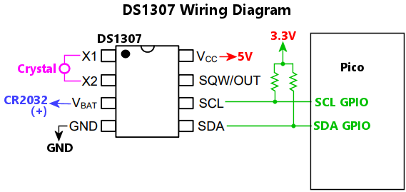 Wiring notes:
The I2C bus number, 0 for I2C0 or 1 for I2C1, where the chip is connected. This chip has a fixed I2C address, so you only have to specify the bus number; there's no need to specify the address.
Configures a DS3231M, which allows the Pico to keep track of the current date and time even when it's powered off. The Pico can keep track of time by itself as long as it's running, but its clock is reset to zero every time the Pico CPU resets, so it needs an outside source to get the time after a reset. That source can be an RTC chip like the DS3231M. An RTC chip isn't a necessity, though, because the Pico can get the clock time from the Windows host - most Pinscape-aware software, such as DOF and the Config Tool, automatically update the Pico with the clock time whenever you run them. But it's better still if the Pico is equipped with its own always-on clock source. An RTC chip like the DS3231M can be equipped with a coin cell battery that will keep its clock running even when the host computer is powered down or the Pico is disconnected.
There's never a need to manually set the date/time on the RTC chip. The Pinscape firmware will automatically set the chip clock whenever it gets a clock update from the Windows host. And Pinscape automatically reads the RTC chip when the Pico boots.
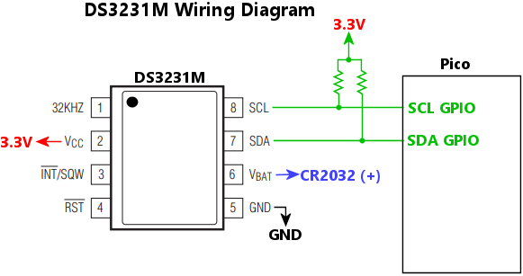 Wiring notes:
The I2C bus number, 0 for I2C0 or 1 for I2C1, where the chip is connected. This chip has a fixed I2C address, so you only have to specify the bus number; there's no need to specify the address.
Configures details relevant to the expansion board environment, if any.
The Pico by itself is a pretty bare-bones microcontroller, so using it to control a virtual pinball environment will usually require a collection of add-on chips, such as PWM controllers, high-power switching circuits, and sensors. These sorts of things can be connected directly to the Pico with ad hoc wiring, but most people will probably prefer to use purpose-built circuit boards that are designed to host the Pico and a collection of suitable peripherals. We refer to these as Expansion Boards because they expand upon the basic capabilities of the Pico.
We use the term "Expansion Boards" generically, not to refer to any particular board design. There is a "reference" Pinscape Pico Expansion Board that I created for the project, but the Pinscape firmware isn't at all tied to that particular design - the reference board is just one of many possible expansion board sets. The Pinscape software doesn't place any requirements on what chips or devices an expansion board should include. This configuration object therefore only includes some abstract information that's likely to be commonly needed in different expansion board setups. Everything related to specific peripheral devices is handled through separate configuration objects related to the individual devices.
Settings for software control over the power supply to peripheral devices on the expansion board, if any. Some expansion boards might provide a mechanism that lets the Pinscape software control the power supply to the peripheral chips on the expansion board, via a Pico GPIO port. Software power control is useful because it allows Pinscape to execute a hard reset on all of the on-board peripherals, by cycling their power supply. If your expansion board has such a feature, you can configure it here.
Cycling the power is usually the most certain way of clearing any error or fault conditions on the chips. Some peripherals chips are complex enough that they can glitch or lock up, much like a computer program can, due to bugs in the chip, or invalid commands sent from the Pico, or electrical faults in the external environment. Whatever the cause, some chips that get into such a state can stay stuck there until the power is cycled. One obvious way to cycle the power would be to physically unplug all of the power inputs to the board, but this can be extremely inconvenient in a pin cab, where the board is locked inside the cabinet, and might be hard to reach even after opening up the cabinet. It might seem like the next best thing would be to do a software reset on the Pico, or reboot the whole PC, but those might not be good enough, because they might not actually cut power to the Pico or the expansion board. The Pico gets its power through the USB cable, and most PCs leave USB power on continuously even when the PC is rebooting or shut down. That's why some expansion boards might give the Pico a way to control peripheral power through a GPIO port directly. When you enable this feature, Pinscape uses it to cut power to all of the peripherals during each software reset, ensuring that they're all reset to their pristine power-on conditions every time the Pinscape software starts up, with no need to unplug any cables.
Polarity of the GPIO port signal that controls peripheral power: true means that power is enabled when the GPIO port is high (that is, it outputs a 3.3V signal); false means that power is enabled when the GPIO port is low (0V output).
The GPIO port number that controls the peripheral power supply.
The duration in milliseconds of the reset power-off period. Pinscape shuts off power to all of the peripherals for this amount of time during a software reset, to fully reboot all devices and restore them to power-on conditions. Some devices might respond instantly to a power cut due to internal capacitors that continue to provide power briefly after the external supply goes dark. This parameter lets you extend the blackout period as needed to ensure that all devices on your expansion board fully reset every time. The default is 250 ms, which should be plenty for most devices.
Time after restoring peripheral power to wait for devices to cycle, in milliseconds. Many devices require a non-zero time after power-on to complete their internal initialization procedures. This is typically on the order of a few milliseconds, but some devices need longer, and if so, this will usually be documented in the device's data sheet so that implementers will know to incorporate proper wait times in their software drivers. The default is 100 ms, which should be plenty for almost any device.
Configures Pinscape Pico's custom USB HID protocol interface, which host PC programs can use to send commands to the Pico to activate and control feedback device output ports. This is the interface that DOF uses to activate feedback effects on the Pico, and the protocol is documented, so it's available to any other programs that wish to use it.
The Feedback Controller interface is enabled by default. The only scenario where you should disable it is for strict LedWiz emulation. A genuine LedWiz has only one HID interface, which accepts commands using the proprietary LedWiz protocol. If you want to make a Pinscape Pico unit fully emulate an LedWiz at the USB level, it's necessary to disable all of Pinscape's other HID interfaces, including this one, as well as the keyboard, gamepad, XInput, and Open Pinball Device interfaces. See the ledWizProtocol object for more details on setting up LedWiz emulation.
Enables or disables the interface. The interface is enabled by default. The only common reason for disabling it is for strict LedWiz emulation.
Configures a virtual gamepad input to the PC. Pinscape can optionally present itself to the PC as a simulated USB gamepad, with six analog joystick axes (X, Y, Z, rotational RX, RY, RZ), two analog sliders, and 32 buttons. Windows has good built-in support for USB gamepads, and most of the major pinball simulators can accept input via gamepads, so this makes an excellent way to map physical inputs on the Pico to game control functions in your pinball games.
Pinscape only sets up the USB gamepad if you tell it to via this object. (Gamepads can sometimes create compatibility problems for other gaming software you're using, other than pinball simulators, which is why Pinscape makes this feature optional.) The gamepad can be combined with any of the other virtual USB devices (keyboard, XBox controller). Pinscape can emulate all of these devices at once.
The mappings for joystick axes and sliders are specified as part of the gamepad property. There are some common conventions for how the axes are mapped for the pinball simulators: the accelerometer nudge input is usually mapped to joystick X and Y, and the plunger is usually mapped to joystick Z. But these mappings are only conventions, and most of the simulators are flexible about remapping them arbitrarily, so Pinscape doesn't impose any standard mappings. It allows you to map any of the axis sources to any of the nominal joystick axes and sliders.
Gamepad buttons aren't defined via the gamepad property. Instead, those mappings are handled in the buttons section, where you specify the input ports where the physical buttons are connected, and what actions they perform when pressed. One of the actions you can assign there is to generate a joystick button press.
Set this to true to enable the virtual USB gamepad, false to omit it from the USB setup.
Sets the data source for the gamepad's RX (rotational X) axis, using the same notation as gamepad.x.
Sets the data source for the gamepad's RY (rotational Y) axis, using the same notation as gamepad.x.
Sets the data source for the gamepad's RZ (rotational Z) axis, using the same notation as gamepad.x.
Sets the data source for the gamepad's Slider #1 axis, using the same notation as gamepad.x.
Sets the data source for the gamepad's Slider #2 axis, using the same notation as gamepad.x.
Sets the data source for the gamepad's X axis. This is optional; if you omit it, the axis will still be present in the USB virtual gamepad you see on the PC, but it'll just sit stationary at the center position all the time. The axis data source is specified as a string, naming the underlying physical control to use as the axis position.
| Axis name | Description |
|---|---|
| "abs(source)" | Takes another source, such as "nudge.x", and takes the absolute value of each reading |
| "ads1115[n]" | If an ADS1115 ADC chip is configured, reports the reading from the nth logical channel, numbered from 0 |
| "ads1115_m[n]" | If multiple ADS1115 ADC chips are configured, reports the reading from the nth logical channel of the mth chip, numbered from 0; for example, "ads1115_1[0]" selects the first channel of the second chip |
| "lis3dh.temperature" | If an LIS3DH accelerometer is configured, reports the reading from its temperature sensor |
| "lis3dh.x" | If an LIS3DH accelerometer is configured, reports the raw reading from its X axis |
| "lis3dh.y" | If an LIS3DH accelerometer is configured, reports the raw reading from its Y axis |
| "lis3dh.z" | If an LIS3DH accelerometer is configured, reports the raw reading from its Z axis |
| "lis3dsh.temperature" | If an LIS3DSH accelerometer is configured, reports the reading from its temperature sensor |
| "lis3dsh.x" | If an LIS3DSH accelerometer is configured, reports the raw reading from its X axis |
| "lis3dsh.y" | If an LIS3DSH accelerometer is configured, reports the raw reading from its Y axis |
| "lis3dsh.z" | If an LIS3DSH accelerometer is configured, reports the raw reading from its Z axis |
| "mc3416.x" | If an MC3416 accelerometer is configured, reports the raw reading from its X axis |
| "mc3416.y" | If an MC3416 accelerometer is configured, reports the raw reading from its Y axis |
| "mc3416.z" | If an MC3416 accelerometer is configured, reports the raw reading from its Z axis |
| "mxc6655xa.temperature" | If an MXC6655XA accelerometer is configured, reports the reading from temperature sensor |
| "mxc6655xa.x" | If an MXC6655XA accelerometer is configured, reports the raw reading from its X axis |
| "mxc6655xa.y" | If an MXC6655XA accelerometer is configured, reports the raw reading from its X axis |
| "mxc6655xa.z" | If an MXC6655XA accelerometer is configured, reports the raw reading from its X axis |
| "negate(source)" | Takes another source, such as "nudge.x", and reports the negative of the original value |
| "nudge.vx" | Nudge X velocity, from the processed nudge information as configured in the "nudge" configuration section |
| "nudge.vy" | Nudge Y velocity, from the processed nudge information as configured in the "nudge" configuration section |
| "nudge.vz" | Nudge Z velocity, from the processed nudge information as configured in the "nudge" configuration section |
| "nudge.x" | Nudge X acceleration, from the processed nudge information as configured in the "nudge" configuration section |
| "nudge.y" | Nudge Y acceleration, from the processed nudge information as configured in the "nudge" configuration section |
| "nudge.z" | Nudge Z acceleration, from the processed nudge information as configured in the "nudge" configuration section |
| "null" | No data source; just sits at 0 (the center position) |
| "offset(source, amount)" | Takes another source, such as "nudge.x", and adds a fixed offset to each reading |
| "pico_adc" | If the Pico ADC is configured (via "pico_adc"), reports the input reading from its first configured channel |
| "pico_adc[0]" | Same as pico_adc |
| "pico_adc[1]" | Reports the second Pico ADC channel, if two or more channels are configured |
| "pico_adc[2]" | Reports the third Pico ADC channel, if three or more channels are configured |
| "pico_adc[3]" | Reports the fourth Pico ADC channel, if four or more channels are configured |
| "plunger.sensor" | The raw plunger sensor reading, bypassing calibration and other processing |
| "plunger.speed" | The current plunger speed reading |
| "plunger.z" | The standard processed plunger position, taking into account calibration and firing event detection |
| "plunger.z0" | The calibrated plunger position, without any firing event detection |
| "scale(source, amount)" | Takes another source, such as "nudge.x", and scales it by a constant factor |
| "sine(period, offset)" | A synthesized sine wave, with the given period in milliseconds and starting offset in millseconds |
Sets the data source for the gamepad's Y axis, using the same notation as gamepad.x.
Sets the data source for the gamepad's Z axis, using the same notation as gamepad.x.
Configures the Pico's I2C0 bus controller.
I2C is an industry-standard bus interface that allows multiple external peripherals to be connected to the Pico through just two GPIO ports ("SDL" and "SCL", for the data and clock signals, respectively). Being able to connect multiple peripherals through just two ports is extremely helpful with the Pico given its relatively small number of GPIO pins. The Pico has two I2C units, which lets you set up two separate I2C buses that can operate concurrently (which can be useful if you have some peripherals that hog the bus with large and/or frequent transfers, since only one peripheral on each bus can be transferring data at any given time).
The "i2c0" JSON object sets up the configuration for the first of the two I2C units. The two units are identical, except that each one connects to a different subset of the GPIO pins, so the choice of which unit to use boils down to which pins you plan to connect to. If you're using pins that are only wired internally to I2C0, you have to use the I2C0 unit, and likewise for pins connecting to I2C1. The main thing you have to configure for each I2C unit is the GPIO pins it's using: one for the "SDA" function, one for the "SCL" function. In the physical wiring, you connect the designated Pico SDA pin to the SDA pins for each of the peripherals that you want to attach to the bus, and likewise for the SCL pins.
Sets the operating mode for the bus:
Controls the internal pull-up resistors on the SDA and SCL GPIO ports. Set to true to enable the internal pull-ups, false to disable them. The default if this isn't specified is true.
The I2C bus design requires pull-up resistors on the SDA and SCL lines, to the bus logic level (3.3V for the Pico). One easy way to satisfy this requirement is to enable the Pico's internal GPIO port pull-up resistors on the SDA and SCL ports. However, this isn't considered good practice, because the Pico's internal pull-ups are too weak. Typical I2C pull-up resistors should be in the neighborhood of 4K to 10K ohms (the exact value depends upon how many chips are sharing the bus), whereas the Pico's internal pull-ups are around 50K. The difference can affect signal quality on the bus, so it's better to use external pull-ups where you can choose the appropriate value according to the bus configuration. If your hardware design does include its own pull-ups, it's best to disable the Pico's internal ones, so that they're not added in parallel to the values you specifically chose.
Another scenario where it might be important to disable the internal pull-ups is where the chips on your I2C bus have a separate power supply from the Pico's 3.3V supply. The reference Pinscape Pico Expansion Boards use such a design, to allow the Pico to perform a hard reset on the peripheral chips by power-cycling them under software control. It might be harmful to some peripherals to feed them power via the I2C bus lines while their main power input is disabled, so in this setup it's best to provide power to the I2C pullups through the peripheral power supply rather than through the Pico's main 3.3V power, which is what the internal pull-ups are connected to.
Sets the GPIO port number for the SCL function for this I2C unit. The GPIO port selected must be one of the I2C0 SCL capable pins: 1, 5, 9, 13, 17, or 21.
Sets the GPIO port number for the SDA function for this I2C unit. The GPIO port selected must be one of the I2C0 SDA capable pins: 0, 4, 8, 12, 16, or 20.
Sets the bit rate for the I2C bus; the default is 400000, which is compatible with all of the devices that Pinscape currently supports. The Pico's I2C units support speeds from 0 to 1000000 bits per second, but speeds above 400000 aren't as widely supported by peripheral devices.
Configures the Pico's I2C1 bus controller (the second of the Pico's two I2C controllers). The contents are the same as for the "i2c0" object. The I2C1 unit is only connected internally within the Pico to a subset of the GPIO ports, so you can only configure I2C1 with that limited set of ports.
Sets the operating mode for the bus:
Controls the internal pull-up resistors on the SDA and SCL GPIO ports. Set to true to enable the internal pull-ups, false to disable them. The default if this isn't specified is true.
The I2C bus design requires pull-up resistors on the SDA and SCL lines, to the bus logic level (3.3V for the Pico). One easy way to satisfy this requirement is to enable the Pico's internal GPIO port pull-up resistors on the SDA and SCL ports. However, this isn't considered good practice, because the Pico's internal pull-ups are too weak. Typical I2C pull-up resistors should be in the neighborhood of 4K to 10K ohms (the exact value depends upon how many chips are sharing the bus), whereas the Pico's internal pull-ups are around 50K. The difference can affect signal quality on the bus, so it's better to use external pull-ups where you can choose the appropriate value according to the bus configuration. If your hardware design does include its own pull-ups, it's best to disable the Pico's internal ones, so that they're not added in parallel to the values you specifically chose.
Another scenario where it might be important to disable the internal pull-ups is where the chips on your I2C bus have a separate power supply from the Pico's 3.3V supply. The reference Pinscape Pico Expansion Boards use such a design, to allow the Pico to perform a hard reset on the peripheral chips by power-cycling them under software control. It might be harmful to some peripherals to feed them power via the I2C bus lines while their main power input is disabled, so in this setup it's best to provide power to the I2C pullups through the peripheral power supply rather than through the Pico's main 3.3V power, which is what the internal pull-ups are connected to.
Sets the GPIO port number for the SCL function for this I2C unit. The GPIO port selected must be one of the I2C1 SCL capable pins: 3, 7, 11, 15, 19, or 27.
Sets the GPIO port number for the SDA function for this I2C unit. The GPIO port selected must be one of the I2C1 SDA capable pins: 2, 6, 10, 14, 18, or 26.
Sets the bit rate for the I2C bus; the default is 400000, which is compatible with all of the devices that Pinscape currently supports. The Pico's I2C units support speeds from 0 to 1000000 bits per second, but speeds above 400000 aren't as widely supported by peripheral devices.
The id object lets you set the way the Pinscape Pico identifies itself to applications on the PC.
The most important sub-property is unitNum, which sets the unit number that DOF (DirectOutput Framework) uses to address the device. You can also give the device a name, which the Pinscape Pico Config Tool and similar tools CAN display in their lists of devices, to make it easier for you to keep track of which Pico is which if you have more than one connected.
Sets the LedWiz unit number or range for LedWiz emulation on the PC. This tells the LedWiz.dll library on the PC which unit number(s) to use for the virtual LedWiz device(s) it presents to applications. If you don't have any real LedWiz devices in your system (or any other devices that emulate the LedWiz), you should set this to 1, which is the default if you omit it. If you do have any other LedWiz devices (genuine or emulated), set this to a value that doesn't conflict with any of the other devices. For example, if you have two other LedWiz devices with unit numbers 1 and 2, you should set this to 3. That will allow applications to distinguish all three devices without any conflicts. LedWiz unit numbers are limited by the LedWiz's design to the range 1 to 16.
Pinscape Pico doesn't by itself emulate an LedWiz. It doesn't implement the LedWiz USB protocol, so applications that look for the LedWiz purely by its USB interface won't find the Pico, whether you set this property or not. Fortunately, most of the legacy LedWiz-aware applications never look at the USB device interface directly, because Groovy Game Gear (the LedWiz's manufacturer) didn't ever publish the details of the interface; instead, the official application interface to the device was through the LEDWIZ.DLL library that Groovy Game Gear provides. Pinscape Pico takes advantage of this to implement its LedWiz emulation, by providing a replacement version of the LEDWIZ.DLL library that has special knowledge of the Pinscape Pico USB interface.
You can find the replacement DLL at http://mjrnet.org/pinscape/dll-updates.html#LedWiz.dll. Replace any existing copies of LedWiz.dll on your system with that library, and it will provide legacy LedWiz-aware applications with a virtual LedWiz device representing the Pinscape Pico unit. The LedWiz.dll replacement uses the unit number that you set with this property to determine what ID to use for the virtual LedWiz unit presented to applications.
If you have more than 32 logical output ports on this device, LedWiz.dll will create two or more virtual LedWiz units to represent the Pico, because each LedWiz (real or virtual) can only have at most 32 ports. For example, if you've configured 96 logical output ports on the Pico, LedWiz.dll will create three virtual LedWiz units to represent this single Pico. The three units are given sequential ID numbers, starting at the ledWizUnitNum you specify, so if ledWizUnitNum is set to 8, the three units in this example will be assigned LedWiz unit IDs 8, 9, and 10. Alternatively, you can specify exactly which IDs to assign by entering ledWizUnitNum as an array. For example, if you set this to [8, 10, 12], and three virtual LedWiz units are needed, they'll be assigned IDs 8, 10, and 12. (The order of the array doesn't matter; the IDs are always assigned in increasing numerical order.) The array format lets you skip over IDs used by other devices in your system.
Set this to zero to disable the LedWiz.dll emulation for this unit. The LedWiz.dll library won't create a virtual LedWiz to represent this Pico, so the Pico won't be visible at all to legacy LedWiz-aware applications.
LedWiz emulation isn't needed for DOF-based applications, because DOF has direct support for Pinscape Pico.
Sets a name for the device to show in the Config Tool device list. This is purely for display purposes, so it can be anything you like. If you have multiple units attached, this is meant to make it easier to tell which is which when you're looking at the configuration list.
Sets the Pinscape Unit Number for this device. The Unit Number is how DOF and other pinball software identifies the device, and it's really only needed if you have more than one Pinscape Pico attached to your system. You should number each Pinscape Pico unit starting at 1, so the second should be unit 2, etc. Use the same number when you're setting up your DOF Config Tool settings for the device. If you omit this, the default is unit 1, so you don't have to set it at all if you only have one Pinscape Pico. Don't count KL25Z Pinscape units in the numbering - DOF recognizes those as a separate device type, so they have their own separate numbering.
Configures the IR remote control receiver. Pinscape lets you connect a TSOP384xx sensor, which can receive the type of IR signal sent by the IR remote controls for most televisions and other consumer electronics.
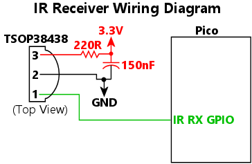 Wiring notes:
Sets the size of the internal buffer that the receiver uses to store incoming signals while it's processing them. This is in units of pulses received, and it takes about two bytes of RAM per unit. The default is 128, which should be ample.
Sets the GPIO port connected to the DATA/OUT pin of the TSOP384xx IR sensor. This is the only GPIO port connection needed for the sensor (the only other connections it needs are 3.3V power and ground).
Configures the IR remote control transmitter. Pinscape lets you connect an IR emitter to a Pico GPIO port, to send IR remote control commands to your TVs and any other IR-capable devices in your pin cab. The emitter is simply an LED that emits light in the IR part of the spectrum.
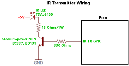 Wiring notes:
Sets the GPIO port where the IR emitter is connected. The emitter must be connected as an "active high" output, meaning that the emitter is activated when the GPIO port is drive high, to 3.3V output.
Configures virtual USB keyboard input to the PC. Pinscape can optionally present itself to the PC as a USB keyboard, allowing you to set up buttons to send key presses to the PC as though you were pressing the keys on a physical keyboard. Windows handles mulitple keyboards seamlessly, so enabling the Pinscape virtual keyboard won't affect your actual keyboard. You can combine the virtual keyboard with any of the other virtual USB devices (gamepad, XBox controller) - Pinscape can emulate all of these device types at once.
Note that you don't specify any key mappings as part of the 'keyboard' section in the JSON file. Instead, you define key presses in the parts of the JSON file related to handling input that triggers key presses, particular the buttons section.
Set this to true to enable the keyboard emulation. Pinscape won't create its virtual keyboard unless you explicitly tell it to by setting this to true.
Configures Pinscape Pico's LedWiz USB protocol emulation. When this is enabled, the Pico exposes a HID interface that accepts commands using the proprietary USB protocol defined by the commercial LedWiz device, making the Pico appear to legacy LedWiz-aware software as though it were an actual LedWiz hardware unit.
Warning: Enabling LedWiz protocol emulation places some severe restrictions on other Pinscape features. The LEDWIZ.DLL replacement option (see below) should always be the first choice, whenever possible. You should only consider protocol emulation if the LEDWIZ.DLL approach isn't workable for your use case.
When using LedWiz protocol emulation, you usually have to disable all of the other HID features when using this mode: the keyboard, gamepad, XInput, Open Pinball Device, and Feedback Controller interfaces must all be disabled. This restriction comes from the legacy LedWiz software that the protocol emulator is designed to support. The problem is that the older LedWiz software can't distinguish the LedWiz protocol interface from any other HID interfaces on the same device, so those programs are likely to crash or otherwise misbehave if any other virtual HID devices are enabled.
To enable strict LedWiz emulation, the following configuration settings are required:
You can still use the Pinscape Config Tool even when strict LedWiz emulation is in effect, since it uses a separate, non-HID protocol that won't confuse or interfere with any legacy LedWiz software.
The LEDWIZ.DLL replacement alternative: For most virtual pinball cabinet users, there's a better option that doesn't come with all of these restrictions. Instead of emulating the LedWiz at the USB protocol level, you can emulate it on the Windows host, by using the replacement LEDWIZ.DLL available at mjrnet.org/pinscape/dll-updates.html#LedWiz.dll. Nearly all legacy LedWiz applications on Windows access the LedWiz through LEDWIZ.DLL rather than directly through the USB protocol. This makes it possible to give legacy LedWiz applications access to Pinscape simply by replacing the DLL with a new version that knows how to access Pinscape through the Pinscape USB protocols. There's no need for Pinscape to pretend to be an LedWiz at the USB level, because the library intercepts the LedWiz API calls and translates them to the Pinscape USB protocol. This has several advantages:
You should use the LEDWIZ.DLL replacement instead of USB emulation whenever possible. USB emulation should be treated as a last resort, only for cases where you can't use the DLL: for example, you're running on a non-Windows host; or the host has a brittle configuration that makes it impractical to replace the DLL; or the legacy software you want to use accesses the LedWiz directly through its USB interface rather than through the DLL. If the LEDWIZ.DLL approach is unworkable for one of these reasons or some other reason, only then should you consider the USB protocol emulation approach.
Enables or disables LedWiz USB protocol emulation. Disabled by default.
Configures a LIS3DH, which is a three-axis accelerometer chip with 12-bit native resolution. LIS3DH is a popular choice among microcontroller hobbyists because it's available on pre-soldered breakout boards from Adafruit, Sparkfun, and several other vendors. Pinscape Pico can use this chip as the Nudge device data source.
Important: Note that the very similarly named LIS3DH and LIS3DSH are distinct devices that require different handling in the software. If your chip is actually a LIS3DSH, you must use the lis3dsh configuration rules instead.
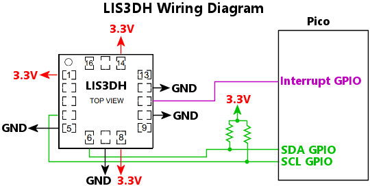 Wiring notes:
The 7-bit I2C address of the chip. The address is determined by the wiring on the chip's SDO/SA0 pin: if the pin is wired to GND, the address is 0x18; if the pin is wired to 3.3V, the address is 0x19.
Sets the dynamic range for the accelerometer readings, in units of standard Earth gravity. This device allows settings of 2, 4, 8, or 16. The default is 2, which is usually the best setting for a virtual pin cab, since this provides the best sensitivity for mild nudges. Higher ranges sacrifice precision for dynamic range. In a pin cab, we don't really need wide dynamic range, since nudges past a certain point simply result in a TILT condition, so it's more useful to take advantage of the highest available precision to allow finer gradations of effects for milder nudges.
The I2C bus number, 0 for I2C0 or 1 for I2C1, where the chip is connected.
The GPIO port number where the chip's INTERRUPT pin is wired into the Pico, if any. This can be omitted if the interrupt line isn't connected to the Pico. Wiring the interrupt connection is preferred, because it lets the chip notify the Pico immediately when a new sample is available. Without this connection, the Pico has to poll the chip periodically, which can slightly increase the latency between a new sample becoming ready on the chip and the Pico reading it across the I2C bus.
Configures a LIS3DSH, which is a three-axis accelerometer chip with 16-bit native resolution. LIS3DSH is a popular choice among microcontroller hobbyists because it's available on pre-soldered breakout boards from Adafruit, Sparkfun, and several other vendors. Pinscape Pico can use this chip as the Nudge device data source. The chip is no longer in production, but for now (2025), there are still listings for LIS3DSH breakout boards on eBay and Amazon.
Important: Note that the very similarly named LIS3DH and LIS3DSH are distinct devices that require different handling in the software. If your chip is actually a LIS3DH, you must use the lis3dh configuration rules instead. Some of the eBay and Amazon sellers are reportedly listing their boards as the -SH type, but are actually shipping the -H chip. If you're not sure, you can check the Pinscape startup log to see if the chip is responding at the expected I2C address; if it's not, try changing the configuration settings to use the other chip type.
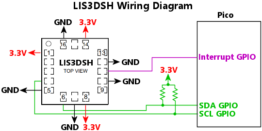 Wiring notes:
The 7-bit I2C address of the chip. The address is determined by the wiring on the chip's SEL pin: if the pin is wired to GND, the address is 0x1E; if the pin is wired to 3.3V, the address is 0x1D.
Sets the dynamic range for the accelerometer readings, in units of standard Earth gravity. This device allows settings of 2, 4, 6, 8, or 16. The default is 2, which is usually the best setting for a virtual pin cab, since this provides the best sensitivity for mild nudges. Higher ranges sacrifice precision for dynamic range. In a pin cab, we don't really need wide dynamic range, since nudges past a certain point simply result in a TILT condition, so it's more useful to take advantage of the highest available precision to allow finer gradations of effects for milder nudges.
The I2C bus number, 0 for I2C0 or 1 for I2C1, where the chip is connected.
The GPIO port number where the chip's INTERRUPT pin is wired into the Pico, if any. This can be omitted if the interrupt line isn't connected to the Pico. Wiring the interrupt connection is preferred, because it lets the chip notify the Pico immediately when a new sample is available. Without this connection, the Pico has to poll the chip periodically, which can slightly increase the latency between a new sample becoming ready on the chip and the Pico reading it across the I2C bus.
Customizes the message logging options. As the Pinscape firmware runs, it generates a series of human-readable messages that describe important events, especially things related to the initial setup after a reboot, when the software is going through the JSON configuration file and initializing all of its internal modules and external hardware peripherals. Log messages include confirmations when setup tasks succeed, and error messages when tasks fail, all intended to help you troubleshoot any problems you're noticing with the system. The "logging" object lets you customize details about the log message store.
The log messages are kept in RAM on the Pico, but you can view them at any time using the Pinscape Config Tool, or by connecting a terminal window to one of the Pico's serial ports - its USB virtual COM port, or its physical UART port.
The size, in bytes, of the memory (RAM) buffer that Pinscape uses to store its log messages. The default is 8192 bytes (8K), which is also the minimum size. You can increase the size up to 65536 bytes (64K). The Pico has a limited amount of RAM (about 256K), so the default log buffer is at the low end of the range to avoid eating up too much memory, in case it's needed for other subsystems. You can observe the actual memory usage for your setup using the Config Tool. In most cases, Pinscape only needs about 40K for a fully populated system, leaving lots of memory free for you to increase the log buffer size if you wish. Pinscape automatically reuses space in the buffer as needed by discarding older messages as new messages are added, so it's perfectly okay for the buffer to "overflow". You'll always be able to see the most recent messages no matter how big or small the buffer is; making the buffer larger just lets you see a longer history of messages going back further, since older messages won't have be discarded as quickly as with a smaller buffer. Note that the message history never goes back any further than the last Pico reboot, because the messages are kept in RAM, which is cleared after a reboot.
If true, the log uses ANSI "escape codes" to show each message type in a distinct color (red for errors, yellow for warnings, etc). The default is false (no color coding). The color coding is designed to make it easier to skim through the log and scan for particular types of messages, which can be really helpful if you enabled most of the message types in the "filter" setting. There are two reasons you might wish to turn this off, though. The first is that the color codes take up more space in the log message buffer, so you'll be able to see more older messages if you disable coloring. The second is that some terminal programs might not understand the ANSI codes. The codes have been standard for a very long time, so nearly all good terminal programs handle them properly, but some will just show them as gibberish.
This selects the subset of messages that are kept in the log. Pinscape assigns a "type code" to every message, listed below. The filter lets you select which type codes to keep in the log and which to discard. The property string consists of a list of type codes to include in the log, separated by spaces. For example, to include only warnings and errors, write "warning error". Alternatively, you can tell Pinscape to include everything except the ones you explicitly exclude, by starting the string with a tilde, "~", and then listing the message types to exclude. To include everything except debug messages, for example, you could write "~debug debugex tinyusb". Finally, you can tell Pinscape to include all message types by writing "*".
| Type code | Description |
|---|---|
| "debug" | Debugging messages, with internal details that are mostly useful for developers working on the firmware |
| "debugex" | Extended debug messages, with even more technical detail than "debug" messages; this type is mostly for messages that are produced so abundantly that even the developers only want to see them when debugging something specific |
| "error" | Error messages, generated when an operation fails unrecoverably |
| "warning" | Warnings; these call flag configuration settings that are likely to cause unintended effects, as well as minor operational errors |
| "info" | Informational messages; these can be helpful to confirm that things you expect to be happening are actually happening |
| "config" | Configuration messages; these confirm successful setup operations and describe the final set of parameters chosen, which can be helpful to see the effect of defaults and to confirm that devices are working as expected |
| "vendor" | Messages related to the USB "vendor interface"; these are mostly internal debugging messages for the developers |
| "xinput" | Messages related to the XBox Controller (XInput) device emulation |
| "tinyusb" | Messages related to the USB hardware interface; these are for system-level debugging, and are disabled at compile-time in regular builds, regardless of the "tinyusb" filter setting (they can only be enabled at compile time, because TinyUSB's logging is so voluminous that it significantly affects performance even with the run-time filter disabled) |
If true, the log includes a timestamp for each message. The default is false. The Pico doesn't have an on-board clock/calendar, but it can get the date and time from the Windows host whenever it connects to the Config Tool or DOF, and it can include this information log messages. Before the Pico gets the date/time from the Windows host, it just stamps messages with the time since the Pico rebooted, which you can easily identify because they'll show the year 0000. The reason the timestamp is optional is that it takes up space in the log buffer, so the buffer will be able to keep a longer history of older messages if timestamps are omitted.
If true, the log shows the type code for each message. The default is false. The type code takes up additional space in the log buffer, so the buffer will be able to store more older messages if this is disabled.
Configures an MC3416 accelerometer chip.
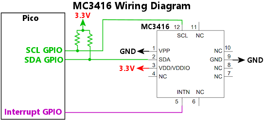
The 7-bit I2C address of the chip. The address is determined by the wiring on the chip's VPP pin; if the pin is wired to GND, the address is 0x4C, if the pin is wired to 3.3V, the address is 0x6C. Set this property according to the VPP pin wiring.
Sets the dynamic range for the accelerometer readings, in units of standard Earth gravity. This device allows settings of 2, 4, 8, 12, or 16. The default is 2, which is usually the best setting for a virtual pin cab, since this provides the best sensitivity for mild nudges. Higher ranges sacrifice precision for dynamic range. In a pin cab, we don't really need wide dynamic range, since nudges past a certain point simply result in a TILT condition, so it's more useful to take advantage of the highest available precision to allow finer gradations of effects for milder nudges.
The I2C bus number, 0 for I2C0 or 1 for I2C1, where the chip is connected.
The GPIO port number where the chip's INT (interrupt) pin is wired into the Pico, if any. This can be omitted if the interrupt line isn't connected to the Pico. Wiring the interrupt connection is preferred, because it lets the chip notify the Pico immediately when a new sample is available. Without this connection, the Pico has to poll the chip periodically, which can slightly increase the latency between a new sample becoming ready on the chip and the Pico reading it across the I2C bus.
Configures an MMA8451Q, a three-axis accelerometer chip with 14-bit native resolution. This was the built-in accelerometer in the venerable FRDM-KL25Z, which is the platform that the original Pinscape Controller (the predecessor to Pinscape Pico) ran on. The MMA8415Q is no longer in production, but old stock is still available as of this writing (2025) - which is fortunate for pin cab builders, because this chip has better resolution and lower noise than any of the devices currently being made. Adafruit sells an MMA8451Q breakout board that's a perfect fit for DIY projects, since the only soldering it requires is a standard 0.1" pin header, easily done by hand.
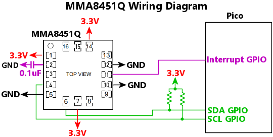 Wiring notes:
The 7-bit I2C address of the chip. The address is determined by the wiring on the chip's SA0 pin: if the pin is wired to GND, the address is 0x1C; if the pin is wired to 3.3V, the address is 0x1D.
Sets the dynamic range for the accelerometer readings, in units of standard Earth gravity. This device allows settings of 2, 4, or 8. The default is 2, which is usually the best setting for a virtual pin cab, since this provides the best sensitivity for mild nudges. Higher ranges sacrifice precision for dynamic range. In a pin cab, we don't really need wide dynamic range, since nudges past a certain point simply result in a TILT condition, so it's more useful to take advantage of the highest available precision to allow finer gradations of effects for milder nudges.
The I2C bus number, 0 for I2C0 or 1 for I2C1, where the chip is connected.
The GPIO port number where the chip's INT1 (Interrupt #1) pin is wired into the Pico, if any. This can be omitted if the interrupt line isn't connected to the Pico. Wiring the interrupt connection is preferred, because it lets the chip notify the Pico immediately when a new sample is available. Without this connection, the Pico has to poll the chip periodically, which can slightly increase the latency between a new sample becoming ready on the chip and the Pico reading it across the I2C bus.
Configures an MXC6655XA accelerometer chip.
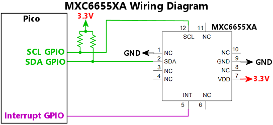
Sets the dynamic range for the accelerometer readings, in units of standard Earth gravity. This device allows settings of 2, 4, or 8. The default is 2, which is usually the best setting for a virtual pin cab, since this provides the best sensitivity for mild nudges. Higher ranges sacrifice precision for dynamic range. In a pin cab, we don't really need wide dynamic range, since nudges past a certain point simply result in a TILT condition, so it's more useful to take advantage of the highest available precision to allow finer gradations of effects for milder nudges.
The I2C bus number, 0 for I2C0 or 1 for I2C1, where the chip is connected. Note that the MXC6655XA has a fixed I2C address, so you only have to specify the bus it's attached to; there's no need to specify the address.
The GPIO port number where the chip's INT (interrupt) pin is wired into the Pico, if any. This can be omitted if the interrupt line isn't connected to the Pico. Wiring the interrupt connection is preferred, because it lets the chip notify the Pico immediately when a new sample is available. Without this connection, the Pico has to poll the chip periodically, which can slightly increase the latency between a new sample becoming ready on the chip and the Pico reading it across the I2C bus.
Configures options for accelerometer-based nudging. The nudge system performs some processing on the raw accelerometer data to make it more presentable to pinball simulator programs on the PC, including noise filtering, tilt bias correction, and velocity integration. Most of the processing options are set up via the Config Tool rather than JSON settings, so that you can experiment with different settings and see their effects on real-time readings without having to repeatedly reboot the device (which is necessary for settings made through the JSON file).
Sets the physical accelerometer device that serves as the source of the nudge data stream. This is normally not required, because the nudge system will automatically choose whichever accelerometer device is configured via its device key. If for some reason you have more than one accelerometer attached, you can use this to select the one to use for nudging, by setting source to a string giving the configuration key for the desired device: "mxc6655xa", "lis3dh", etc.
Select the physical accelerometer device axis to use for the X axis for nudging. The nudge X axis is the side-to-side direction in the pin cab. If your accelerometer is rotated from this orientation, you can use nudge.x to select the appropriate device axis to use. This should be one of "+" or "-" followed by "x", "y", or "z", as in "+x" or "-z". You can use "-" to reverse the physical axis if the accelerometer orientation is backwards from the standard pinball simulator orientation, which has positive X going to the right.
Select the physical accelerometer device axis to use for the Y axis for nudging. The nudge Y axis is the front-to-back direction in the pin cab. If your accelerometer is rotated from this orientation, you can use nudge.y to select the appropriate device axis to use. This should be one of "+" or "-" followed by "x", "y", or "z", as in "+x" or "-z". You can use "-" to reverse the physical axis if the accelerometer orientation is backwards from the standard pinball simulator orientation, which has positive Y going towards the back of the cabinet.
Select the physical accelerometer axis to use for the nudge Z axis. The nudge system currently doesn't make any use of the Z axis, so you can omit this, but you can include it for the sake of completeness, and in case it becomes more important in future versions. This should be one of "+" or "-" followed by "x", "y", or "z", as in "+x" or "-z". You can use "-" to reverse the physical axis if the accelerometer orientation is backwards from the standard orientation, which has positive Z facing up.
Configures Open Pinball Device input to the PC. Open Pinball Device is a proposed open-source standard for a custom HID device type specifically designed for pinball I/O controllers (such as Pinscape Pico) to use as a way to send accelerometer, plunger, and button input to the PC. Pinball simulator programs such as Visual Pinball can use this interface as an alternative to the traditional joystick/gamepad mappings. To enable the interface, simply set OpenPinballDevice.enable property to true.
The details of the new interface are available in a published specification, in the hope that other I/O controller devices and other pinball programs will also adopt it. The goal is to provide a complete functional replacement for the traditional joystick/gamepad method of sending input to the simulators. One benefit is that the traditional joystick method occasionally causes conflicts with non-pinball video game software that expects HID joysticks to be literal joysticks; those conflicts can be eliminated by switching to an explicitly pinball-specific interface, since other video games won't try to access it. Another benefit is that a purpose-built interface will allow for easier configuration in the simulators, with less manual setup required.
Newer versions of Visual Pinball have support for the Open Pinball Device interface. To enable support in VP, use the Keys dialog to set each "axis" entry for the Nudge and Plunger settings to "Open Pin Dev". That will select the corresponding Open Pinball Device axis. While you're at it, you should also check the box "Nudge Input is Velocity", which uses the velocity-based nudge input that Pinscape Pico provides. Velocity-based nudging should provide more natural nudge reactions in the simulator.
The Open Pinball Device interface includes nudge and plunger readings. By default, these are mapped to your accelerometer and plunger sensors in the obvious way, so you don't have to specify any extra properties to get the standard mappings. However, you can override each axis individually with the axis properties: axNudge, ayNudge, etc. If you want to disable one of the axes, set it to "null", which sets up the axis so that it reports a constant 0 reading to the PC. This is especially useful if you have two or more Pinscape Pico units in your system, and both of them are equipped with accelerometers, since it lets you disable input to the PC from one of the accelerometers. The PC expects to see only one accelerometer and one plunger sensor reporting across the whole system, since it makes no sense to have multiple sensor inputs at once. It's therefore useful to be able to disable sensor reporting selectively, so that you can designate one official accelerometer and one official plunger, and tell all of the other devices to keep quiet.
The logical axis source for the nudge acceleration X axis (left/right), using the same syntax as the gamepad axis properties. The default value if this isn't specified is "nudge.x".
The logical axis source for the nudge acceleration Y axis (front/back), using the same syntax as the gamepad axis properties. The default value if this isn't specified is "nudge.y".
Set this to true to enable the Open Pinball Device interface on this Pinscape Pico unit.
The logical axis source for the plunger position axis, using the same syntax as the gamepad axis properties. The default value if this isn't specified is "plunger.z0".
The logical axis source for the plunger speed axis, using the same syntax as the gamepad axis properties. The default value if this isn't specified is "plunger.speed".
The logical axis source for the nudge velocity X axis (left/right), using the same syntax as the gamepad axis properties. The default value if this isn't specified is "nudge.vx".
The logical axis source for the nudge velocity Y axis (front/back), using the same syntax as the gamepad axis properties. The default value if this isn't specified is "nudge.vy".
Configures the logical output ports. The logical output ports provide the interface between PC-side software like DOF, and the physical feedback devices in your system, such as motors, solenoids, and LEDs. This property contains an array of objects, with each object defining one logical output.
Each logical output port has a number that DOF uses to address the port. DOF starts its port numbering at 1, so we do the same thing, to keep things consistent. So the first "outputs" array element is port 1, the second is port 2, etc. This number is quite important because it's how you identify the port when you're setting up devices in the DOF Config Tool. The DOF Config Tool lets you set up the association between each numbered DOF port and a chosen virtual pinball element. That's how DOF knows which numbered port connects to your shaker motor, which connects to your left flipper solenoid, and so forth.
Each logical output port is also associated with a physical output on the Pico (or, in some cases, a virtual output that doesn't connect to anything physical). The output can be simply one of the Pico's GPIO ports, or it can be a port on one of the supported external controller chips, such as the various PWM controller chips, a GPIO extender chip, or a shift register chip.
The cooling time for the port, in milliseconds. This is an amount of time that must elapse between high-power activations of the port. If the port is activated at high power, turned off, and then reactivated at high power a short time later, the new activation is limited to the powerLimit setting until the cooling time elapses. This is designed to avoid pathological cases where the host is switching the device on and off so rapidly that the high-power time limit never kicks in, but nonetheless leaving it on long enough overall that it could overheat. The cooling time ensures that the duty cycle is reduced in this situation, providing an additional layer of protection in addition to the time limit.
Selects the physical output port associated with this logical DOF port.
Set this to true to enable gamma correction on the port. Gamma correction adjusts the PWM brightness level to better match human visual perception of brightness, so that a DOF setting of X/2 looks half as bright as X. This is most useful for ports connected to LEDs and other light sources.
Invert this port's DOF level, so that a DOF level of 255 sets the physical port fully OFF; DOF level 0 sets the physical port level fully ON; and DOF values in between are likewise reversed. This is intended for use with external circuitry that inverts the sense of the signal, so that the attached device turns ON when the physical port is OFF, and vice versa.
With a GPIO port, for example, this turns the port into what's known as a low-side switch, where the device gets its GND connection through the port, and has a fixed connection to the power supply voltage. To use a GPIO port in this mode, connect the positive terminal of the device to be controlled, such as an LED, directly to +3.3V power, and connect the device's negative terminal to the GPIO port. With this physical wiring, the device will turn ON when the port is LOW. The 'inverted' property sets the output port logic to match this wiring, so that the GPIO port is physically set LOW when DOF sets the port ON.
Selects the type of physical device associated with the port.
| Device type | Description |
|---|---|
| "tlc59116" | An output port on a TLC59116 PWM output controller chip |
| "tlc5940" | An output port on a TLC5940 PWM output controller chip |
| "tlc5947" | An output port on a TLC5947 PWM output controller chip |
| "pca9685" | An output port on a PCA9685 PWM output controller chip |
| "pca9555" | An output port on a PCA9555 GPIO extender chip (these are digital on/off ports, with no PWM control) |
| "74hc595" | An output port on a 74HC595 shift register chip (the chip can be configured with digital on/off ports or PWM ports) |
| "gpio" | A Pico GPIO port |
| "workerPico" | An output port on an auxiliary Pico running the PWMWorker firmware |
| "zblaunch" | A virtual port that activates ZB Launch Mode when DOF signals that the port is on |
| "shareGroup" | A virtual port that sends output to a designated group of ports that can be shared with other "shareGroup" ports |
| "virtual" | A virtual port that doesn't control any physical device |
Connects the port to a 74HC595 shift register output chip. These output ports are digital on/off ports (without any PWM brightness control).
The 74HC595 daisy chain number, if you've set up more than one daisy chain. This is the index of the array entry for the chip in the "74hc595" array in the JSON configuration file; the first array entry is chain 0, the second is chain 1, and so on. If you only have one 74HC595 daisy chain in your system (which is almost always the case - it's rare to have more than one), you can omit this, since the firmware will know to use the one-and-only chain in this case.
The index of the chip in the daisy chain of chips. The 74HC595 is designed so that multiple chips can be chained together, one after the next. Only one chip has to be connected directly to the Pico GPIO ports; the rest just connect to the next chip in line. When you set up a chain like this, the first chip in the chain - the one that's connected directly to the Pico - is designated as chip number 0. The next chip is designated as chip number 1, and so on. Enter that chip number here.
This is the port on the chip to connect to, which can be expressed as a number from 0 to 7, or a label of the form "QA" to "QH", "A" to "H", or "Q0" to "Q7". Some data sheets label the output pins as Q0 through Q7, some label them QA to QH, and some just label them A to H. Pinscape accommodates all of these different naming conventions here.
Connects the logical port to a physical GPIO port on the Pico. The GPIO is set up as an output port, which can drive a load up to about 10mA, such as a small LED. Higher-current loads require amplifier circuits.
WARNING: Pico GPIO ports are for low-power 3.3V devices only. Never connect a motor, solenoid, incandescent lamp, or high-current LED directly to a Pico GPIO port, and never connect any device with a power supply voltage greater than 3.3V. Connecting high-voltage or high-current devices to a GPIO port runs the risk of damaging or destroying the Pico. The Pico can directly control small LEDs, that run on 10mA or less, and 3.3V or less, but nothing exceeding those limits. For anything higher voltage or higher current, you must use some kind of booster/amplifier circuit. One solution is to use an expansion board set that provides built-in booster circuits. The Pinscape Pico project on github includes a couple of reference designs for full-featured expansion boards that provide plenty of high-power outputs, extra button inputs, and other features that go beyond the Pico's basic built-in capabilities. You can also find pre-built general-purpose driver boards on Amazon and eBay that work with the Pico and other microcontrollers; try searching for "MOSFET board". Or you can build a suitable booster circuit yourself. The PWM Worker Data Sheet shows several general-purpose amplifier circuit designs that work with the Pico and are fairly easy to build.
The PWM frequency to use, in Hertz. Used only if the port is configured for PWM output. You can use this to adjust the frequency if you're experiencing any PWM-related problems with the attached device at the default frequency, such as a flickering LED, or audible buzzing or whining from a motor or solenoid.
This is optional, and it's better to leave it at the default when you don't have a reason to change it, because setting the frequency to a custom value uses more resources on the Pico than using the default does. The Pico has a collection of PWM frequency generators that can be shared among ports when the ports can accept the same frequency, so allowing the system to apply the default frequency makes better use of this sharing capability.
The GPIO port number to use for the output.
Set this to true to configure the output as a PWM port, false to configure it as a simple digital on/off port. The default is true, to set up the port in PWM mode.
Note that PWM ports are a limited resource on the Pico. It's possible to run out of PWM channels if you configure too many output ports in PWM mode. Check the log (you can use the Config Tool's Log Viewer window) to check if any errors occur setting up ports. If you do run out of PWM ports, you can disable PWM for outputs that you're using with devices that don't benefit much from PWM control, such as solenoids.
Connects the port to a PCA9555 GPIO extender chip. These output ports are digital on/off ports (without any PWM controls for different brightness levels).
The index of the chip in the "pca9555" array in the JSON configuration file. The first array entry is chip 0, the second is chip 1, etc.
The port name on the chip. This is a string, and you can use either the notation in the NXP data sheet or the notation in the TI data sheet. NXP uses the format "IO0_0", "IO0_1", etc - that's the letter "I", the letter "O", the number "0" or "1", underscore, and another digit, 0 to 7). TI uses the more bare-bones format "00", "01", etc.
Connects the logical port to an output port on a PCA9685 PWM controller chip.
The index of the chip in the "pca9685" array in the JSON configuration file. The first array entry is chip 0, the second array entry is chip 1, etc.
The port number on the chip, 0 to 15, corresponding to the pins labeled LED0 through LED15 in the data sheet.
Connects the logical port to a pool of shared ports.
See the shareGroup property for an explanation of how share groups work and how to set them up.
Identifies the shared group of ports that this virtual device connects to. The device will be connected to the group of ports that are labeled with the same name in their shareGroup property. If the property is given as an array of strings, the device is connected to all of the groups listed.
Enables "pulse mode" on the port. When the port is in pulse mode, the underlying physical device is only triggered for the duration of a timed pulse when the virtual DOF port switches ON, and then again when it switches back OFF. In between the ON and OFF pulses, the physical device port is left free for other virtual DOF ports to claim.
Pulse mode was designed especially for flippers (but you can use it on any port). Flippers have two special characteristics that make them good candidates for this option. The first is that a flipper can be activated for a lengthy interval, since the player might want to trap the ball. Lengthy activation is bad for sharing, since the flipper port would (without pulse mode) hog the underlying physical device the whole time you're holding the flipper button. That would prevent any other devices from being able to create a sound effect with the same device. In a small cab with only a few devices, this might make all of the other sound effects stop for as long as you're holding the flipper button, which would make for a really odd and unnatural playing experience.
The second special feature of flippers is that modern pinball flippers only really make noise on a modern pinball machine when moving: the clunk when the flipper flips, and another clunk when it un-flips. This means that leaving the DOF solenoid activated the whole time you're holding the flipper button is not only bad for sharing, but also kind of pointless. Why tie up the device when it's just sitting there not making any noise?
Pulse mode takes advantage of these two characteristics to free up the physical device for the time between the ON and OFF pulses, allowing other DOF ports to fire effects on the physical device in the meantime. You still get the ON clunk and the OFF clunks when you press and release the flipper button, thank to the pulses, but the port is free for other uses during times when you're holding down the flipper button.
Note that pulse mode might not be right for you if you want to re-create the coil buzzing sound that many older pinball machines make when the flippers are held on. Most machines made before about 1980 use AC power for the flipper coils, which makes them buzz at the power line frequency (60 Hz in the US) the whole time they're on. Newer machines don't tend to buzz, because their coils use DC power. By the same token, virtual pin cab solenoids don't tend to buzz, because modern virtual cabs tend to use all DC power. But you might be able to get a similar effect from a modern coil by using a PWM port, with the PWM frequency set to 60 Hz and the duty cycle set to 50% (which translates to DOF level 128).
To operate the port in normal "continuous" mode, where the DOF port claims an underlying device continuously for the whole duration of the DOF event (the time between the DOF port turning ON and turning back OFF), simply omit the pulseMode element.
The duration in mlliseconds of the OFF pulse, which occurs when the DOF port switches from ON to OFF.
The duration in milliseconds of the ON pulse, which occurs when the DOF port switches from OFF to ON.
Connects the logical port to an output port on a TLC59116 PWM controller chip.
The index of the TLC59116 chip in the JSON "tlc59116" configuration array. The first array element is chip 0, the second is chip 1, etc.
The output port number on the TLC59116 chip, 0 to 15, corresponding to the chip pins labeled OUT0 to OUT15 in the data sheet.
Connects the logical port to an output port on a TLC5940 PWM controller chip.
The daisy chain number. This is the index of the TLC5940 daisy chain in the JSON "tlc5940" configuration array. The first array element is chain 0, second is chain 1, etc. If you only have one TLC5940 daisy chain in the system, you can omit this, since the firmware will know you mean the one-and-only.
The index of the chip in the daisy chain of chips. The TLC5940 is designed so that multiple chips can be chained together, one after the next. Only one chip has to be connected directly to the Pico GPIO ports; the rest just connect to the next chip in line. When you set up a chain like this, the first chip in the chain - the one that's connected directly to the Pico - is designated as chip number 0. The next chip is designated as chip number 1, and so on. Enter that chip number here.
The port number on the chip, 0 to 15, corresponding to the output pins OUT0 to OUT15 (as labeled in the data sheet).
Connects the logical port to an output port on a TLC5947 PWM controller chip.
The TLC5947 daisy chain number, as the index of the entry in the "tlc5947" array in the JSON configuration. This is only required if you've set up more than one TLC5947 daisy chain. The first chain the "tlc5947" array is chain 0, the second chain is chain 1, etc. It's rare to need more than one chain, since each chain can accommodate many chips linked together; in the typical case where you only have one daisy chain, this property isn't needed, since the firmware will know you're talking about the one-and-only chain.
The chip number on the daisy chain. The TLC5947 is designed so that multiple TLC5947 chips can be chained together, sharing the same set of Pico ports; the chain is formed by connecting each chip's SOUT pin to the next chip's SIN pin. Chip 0 is the first chip on the chain, which is the one whose SIN pin is connected directly to a Pico GPIO pin. Chip 1 is the next chip after chip 0, and so on.
The port number on the chip, as a number from 0 to 23, corresponding the the physical pins on the chip labeled OUT0 to OUT23.
Sets the port as a "virtual" output, not connected to any physical device. This can be useful for a number of purposes. For example, it lets you set up a placeholder port that you can reference in your DOF configuration without having to set up any hardware for it on the Pico. It's also useful if you want to use a port as a data source for computed outputs on other ports, since it provides a place where DOF can send level updates, and lets you use those level updates in computed "source" formulas for other ports.
Connects the logical port to an output port on an auxiliary Pico running the PWMWorker firmware.
The output port number on the Worker Pico. The Worker Pico has 24 output ports, which we refer to here as port numbers 0 through 23. The port numbering lines up almost exactly with the Pico's normal GPn labeling for its GPIO ports, with one annoying exception: our port number 23 refers to GP28 on the remote Pico. This discrepancy was necessary because Picos don't have a GP23! (Technically, they do have such a port, but there's no pin for it, because it serves a special internal function instead of acting as an ordinary GPIO.)
| Port Number | GPIO port on Worker Pico |
|---|---|
| 0 | GP0 |
| 1 | GP1 |
| 2 | GP2 |
| 3 | GP3 |
| 4 | GP4 |
| 5 | GP5 |
| 6 | GP6 |
| 7 | GP7 |
| 8 | GP8 |
| 9 | GP9 |
| 10 | GP10 |
| 11 | GP11 |
| 12 | GP12 |
| 13 | GP13 |
| 14 | GP14 |
| 15 | GP15 |
| 16 | GP16 |
| 17 | GP17 |
| 18 | GP18 |
| 19 | GP19 |
| 20 | GP20 |
| 21 | GP21 |
| 22 | GP22 |
| 23 | GP28 |
The index of the Worker Pico in the JSON "workerPico" configuration array. The first array element is unit 0, the second is unit 1, etc.
Sets the output as the ZB Launch Mode activation output. When the PC sets this output to ON (via DOF or any other pinball software), Pinscape activates ZB Launch Mode on the Pico, which turns the plunger into a virtual Launch Ball button.
If this is set to true, and the port has a source formula, the source computation is applied even when the USB connection to the host is suspended, or when the cable is disconnected. "Suspended" means that the host is physically connected but not sending data, which on Windows is usually the case when the computer is one of the low-power modes - sleep, hibernate, or shutdown. By default, Pinscape stops applying the source formula at these times, on the assumption that you don't want any feedback devices to activate when the host is powered down. There might be times when you do want selected devices to continue operating during host shutdown, though, such as power indicator lights or effects based on time-of-day considerations. Setting this property to true tells Pinscape to continue operating the port's source even when the USB connection is down.
This property doesn't have any effect if the port doesn't have a source formula. Ports that don't have computed sources take their instructions from the host via the USB connection, so they'll necessarily be off when the USB connection is suspended or broken. This property also doesn't have any effect when the power to the main Pico is off, for the obvious reason that the Pinscape software can only run when the Pico is powered. If the Pico receives power only through the USB port, disconnecting the USB cable will have the side effect of removing power to the Pico. In order to continue running when the USB cable is disconnected, the Pico must have a secondary power source through its VSYS pin.
Assigns a string name to the port. The name can be used to refer to the port elsewhere in the configuration file, such as in tvon.relay.port or plunger.zbLaunch.output. Using a port name in these cross-references instead of a port number makes your configuration file more robust, because a port number in a cross-reference would have to be changed every time you insert or delete a port somewhere before the referenced port. A cross-reference by name isn't affected by changes to the order of the port list.
Set this to true to mark the port as a "noisy" port for Night Mode purposes. All ports marked as noisy are disabled when Night Mode is in effect.
The reduced power limit to apply after the full-power activation time limit (timeLimit) has been exceeded, or during the cooling period after a full-power activation (coolingTime). For a digital on/off port without any PWM control, this should be set to zero to completely shut off the device after the time limit has been exceeded (the equivalent of the Chime Logic feature in KL25Z Pinscape). For a PWM-capable port, this can be set to a reduced PWM duty cycle that keeps the device actuated but is safe to maintain for long periods without overheating the device. This is given as a PWM level from 0 to 255, where 0 is fully off and 255 is fully on.
Places this port in a "share group" pool, which makes the physical output device available for dynamic assignment to different logical DOF ports as DOF events are fired. The property value is a string giving the name of the group to which the port belongs, or an array of strings listing one or more groups.
The purpose of a share group is to trick DOF into believing that you have more physical devices than you really do, by sharing a small number of physical devices across a larger number of logical DOF ports. Each time DOF fires one of its logical ports, Pinscape will look in the share group pool for a device that's not currently in use, and will assign it to the DOF port, just for the duration of this one event. When the event ends and DOF sets the port to OFF, the physical device is released back into the pool for use in a future event.
The most common use case for share groups is DOF jet bumper ports. The standard DOF configuration calls for six ports assigned as jet bumpers - back left, back center, back right, middle left, middle center, middle right. This lets DOF make sure that bumper effects in the game are routed to the right spatial location in your cabinet, so that the sound effect sounds like it's coming from the on-screen location of the bumper. In a small pin cab, though, you might not have room for six separate bumper solenoids - there might only be room for one or two. But it's easier to let DOF think you have the standard six, because that lets you use the existing database of effects assignments, which is all based on the assumption that every cab has six bumper devices. Share groups address this use case by letting Pinscape manage the association between six virtual DOF ports, representing the six bumper devices DOF believes every pin cab should have, and the smaller number of physical solenoids you have installed in your cab.
To set up a share group, you have to configure two sets of ports. The first is the virtual DOF ports. This is the larger group of ports that DOF sees. For the DOF bumper ports example, this would be a set of six ports corresponding to the six standard DOF bumpers (back left, back center, etc). Each of these virtual ports is assigned a shareGroup device:
  outputs: [
    // ... other ports ...
    { device: { type: "shareGroup", group: "bumpers" } },   // DOF rear left bumper port
    { device: { type: "shareGroup", group: "bumpers" } },   // DOF rear center bumper port
    { device: { type: "shareGroup", group: "bumpers" } },   // DOF rear right bumper port
    { device: { type: "shareGroup", group: "bumpers" } },   // DOF mid left bumper port
    { device: { type: "shareGroup", group: "bumpers" } },   // DOF mid center bumper port
    { device: { type: "shareGroup", group: "bumpers" } },   // DOF mid right bumper port
    // ... other ports ...
  ],
Those virtual ports are the ones that you assign in your DOF Config Tool configuration. In your DOF Config Tool settings, under Cabinet > Devices > Port Assignments, you assign the numbered Pinscape ports to the named DOF ports - in our example, the six DOF bumper ports.
The second part of a share group is the physical device ports.
This is the smaller group of ports that represents the actual physical
devices that will be actuated when the DOF effects are triggered. For
these ports, you configure them just like a normal device output port,
specifying the physical device assignment. Then you add the
  outputs: [
    // ... other ports
    { device: { type: "gpio", gp: 7 }, shareGroup: "bumpers" },
    { device: { type: "gpio", gp: 8 }, shareGroup: "bumpers" },
    // ... other ports
  ],
DOF doesn't address these ports directly, so you don't assign them to
anything at all in your DOF configuration. DOF doesn't have to know
these ports even exist. DOF only accesses them indirectly, through the
type:"shareGroup" ports.
Here's how this works during game play. Say that the ball hits the upper left bumper, causing DOF to activate the Pinscape port that you assigned to "10 Bumper Back Left". On the Pinscape side, this port is assigned to a "shareGroup" device with the group name "bumpers", so Pinscape looks for a port with shareGroup:"bumpers" in its properties. In the example above, it'll find the ports assigned to GPIO ports 7 and 8. Pinscape will pick one of these devices that's not already being fired by some other shareGroup port, so let's say that it chooses the one on GPIO 7. Pinscape will activate that port, and it'll also make a note that GPIO 7 is now being used by the Back Left Bumper port for the duration of this event (that is, as long as DOF continues to activate that port).
Now, suppose that we're in multiball mode, and a second ball hits the Mid Right Bumper while this event on GPIO 7 is going on. DOF will fire the Mid Right "shareGroup" device port, and Pinscape will go through the process of identifying an available ports in the "bumpers" group. Since the port on GPIO 7 is already being fired by the Upper Left Bumper event, this event can't use that port. But the port on GPIO 8 is still available, so Pinscape will assign the event to that port.
If a third "bumpers" group event fires while both of these events are still in progress, the third event will simply be ignored, since there aren't any more physical devices available to carry it out.
When DOF finishes with the events on the Back Left Bumper and Mid Right Bumper ports, it'll set the ports to OFF, and Pinscape will release the ports back to the pool of shared "bumper" ports for use in new events.
Pinscape automatically cycles through the pool of shared ports as events arrive, so that the devices get roughly equal use. This is meant to add variety to the effects, so that every bumper hit doesn't sound exactly the same as the last.
Multiple groups: When a physical port's shareGroup property is an array listing multiple groups, the port can be claimed by virtual DOF ports that are assigned to any of the listed groups. Likewise, when a type:"shareGroup" device lists multiple groups in its group property, the device can claim ports from any of the listed groups. This lets you arrange the logical and physical ports into overlapping groups to make better use of the limited number of physical devices.
Going back to our jet bumpers example, suppose we have a mini-cab with just two physical solenoids, one on the left, and one on the right. We'd like to make sure that all of the left-side DOF bumpers get assigned to the left solenoid, so that the sound effects come from the right spatial location, and likewise, that the right-side DOF bumpers get assigned to the right solenoid. That leaves the DOF center bumpers. Since we don't have a third solenoid, we'd like the DOF center bumpers to just go to any solenoid, whichever is available. We can accomplish this with overlapping groups:
  outputs: [
    // ... other ports ...
    //
    // DOF ports
    { device: { type: "shareGroup", group: "left bumpers" } },     // DOF rear left bumper port
    { device: { type: "shareGroup", group: "center bumpers" } },   // DOF rear center bumper port
    { device: { type: "shareGroup", group: "right bumpers" } },    // DOF rear right bumper port
    { device: { type: "shareGroup", group: "left bumpers" } },     // DOF mid left bumper port
    { device: { type: "shareGroup", group: "center bumpers" } },   // DOF mid center bumper port
    { device: { type: "shareGroup", group: "right bumpers" } },    // DOF mid right bumper port
    //
    // Physical ports
    { device: { type: "gpio", gp: 7 }, shareGroup: ["left bumpers", "center bumpers"] },   // left-side physical solenoid
    { device: { type: "gpio", gp: 8 }, shareGroup: ["right "bumpers", "center bumpers"] }, // right-side physical solenoid
    //
    // ... other ports ...
  ],
We've assigned each DOF virtual bumper port to a group based on the cabinet location - left, center, or right. Each physical port is assigned to two groups: one representing its left/right location, and one for the center bumpers. When a DOF "left bumpers" port fires, it can only claim the left-side physical solenoid, since it's the only solenoid in the "left bumpers" group. But when a DOF "center bumpers" port fires, it can claim either physical solenoid, since both are in the "center bumpers" group.
Interaction with direct DOF commands: When a port is assigned to a share group, the port ignores DOF commands sent directly to the port. It only accepts commands from the virtual type:"shareGroup" device port that's currently controlling the share group port. So DOF is still able to send commands to a share group port, but only indirectly, through the port's temporary share group assignment.
Defines a local "data source" for the port, overriding DOF control over the port. Most ports don't have data sources, because you want DOF to control them directly. But in some cases, you want to control a device locally on the Pico, without DOF being involved. In other cases, you might want to apply some modifications to the settings that DOF sends to the port, such as modifying the intensity level, or combining DOF inputs from multiple ports. All of this can be accomplished with data sources. Data sources are essentially formula calculations that you apply to a port, taking some input, applying some calculations, and producing an output that goes to the physical port.
Enter the data source as a string, composed from the functions listed below.
Italics in the function descriptions represent placeholders. These aren't meant to be written literally, but rather must be replaced by the actual values you wish to use. For example, in button(n, on, off), you don't write a literal n where it says n; instead, you substitute a button number. Likewise, you don't write literally on or off in those positions; you substitute the PWM level values to use when the button is ON (pressed) or OFF (not pressed), respectively. So you might write something like 'button(7, 255, 0)' to say that the output port should be at PWM level 255 (100% duty cycle, full brightness) when button 7 is pressed, and PWM level 0 (0% duty cycle, fully off) when the button is not pressed. You can also use another source expression in these positions for more complex effects. For example, 'button(7, blink(500, 500), 0)' makes the output port blink on and off at 500ms intervals when the button is pressed.
| Function | Description |
|---|---|
| Constants | |
| n | The constant numeric value n, which can be an integer or floating-point number; for example, 127 or 5.125 |
| Ports | |
| port(n) | The current computed value of port n (a port number) |
| port('name') | The current computed value of the named port |
| rawport(n) | The current DOF level of port n (a port number), before applying the source formula |
| rawport('name') | The current DOF level of the named port, before applying the source formula |
| #n | The current computed value of port n (a port number) - same as port(n) |
| self | The current DOF level for this port (i.e., the port defining this 'source' formula), before applying the source formula |
| Subsystems | |
| button(n, on, off) | Selects the on or off expression, depending on whether button number n is currently pressed or not |
| button('name', on, off) | Selects the on or off expression, depending on whether the named button is currently pressed or not |
| irrx(on, off) | Selects the on or off expression, depending on whether or not an IR command is being received |
| irtx(on, off) | Selects the on or off expression, depending on whether or not an IR transmission is in progress |
| nightmode(on, off) | If Night Mode is currently engaged, returns the on value, otherwise returns the off value |
| nudge | The current nudge device reading, as a vector value. The X and Y readings are normalized to the range -32768 to +32767. |
| plungercal(on, hold, off) | If plunger calibration is in progress, returns the on value; if the calibration button is being held down before calibration, returns hold; otherwise returns off |
| plungerpos | The current plunger position, on a 0-255 scale, with the "rest" position set to 42; values less than 42 represent positions forward of the rest position, values over 42 are retracted positions, with 255 representing the plunger pulled all the way back |
| plungerposf | The current plunger position, as a floating point value from -32768 to +32767, with 0 representing the resting position, and positive values representing retraction (pulling the plunger back); this is the plunger subsystem's native unit system |
| powersense(off, countdown, relay, ir, on) | Selects one of the sub-sources, according to the current state of the TV ON power-sensing circuit: if the power is currently off, returns off; if the power was just switched on and the TV ON countdown is running, returns countdown; if the TV relay is being pulsed, returns relay; if TV ON IR commands are being sent, returns ir; and when power is on after sending all of the TV ON commands, returns on. |
| time('range', in, out) |
Selects in if the current time of day is known and is within 'range', otherwise selects out. The range is
a string, in one of the following formats:
|
| tvon | TV ON relay state; 0 when off, 255 during a power-on relay pulse, or when latched on |
| xboxled(ledNumber) | Gets the current brightness level of one of the XBox controller LEDs, 1 to 4 |
| xboxrumble(channel) | Gets the current intensity level of one of the XBox rumble motor channels, channel 1 or 2 |
| zblaunch(on, off) | Selects the on or off expression, depending on whether the ZB Launch Ball virtual button is current "pressed" or not |
| zblaunchmode(on, off) | Selects the on or off expression, depending on whether or not ZB Launch Mode is in effect |
| Vectors | |
| x(vector) | Get the x component of a vector value |
| vector.x | Get the x coordinate of a vector value (e.g., nudge.x) |
| magnitude(vector) | Get the magnitude of a vector value |
| vector.magnitude | Get the magnitude of a vector value (e.g., nudge.magnitude) |
| y(vector) | Get the x component of a vector value |
| vector.y | Get the y coordinate of a vector value (e.g., nudge.y) |
| Colors | |
| rgb.b | Get the blue component of an RGB value (e.g., hsb(#10,255,255).b) |
| rgb.blue | Get the blue component of an RGB value (e.g., hsb(#10,255,255).blue) |
| blue(rgb) | Get the blue component of an RGB value (e.g., blue(hsb(#10,255,255))) |
| brightness(rgb) | Translates the RGB value to HSB (hue/saturation/brightness) space, and returns the brightness component |
| grayscale(rgb) | Gets the grayscale level (0 to 255) of the given RGB value |
| grayscale(r, g, b) | Gets the grayscale level of the given RGB value, using the standard RGB-to-grayscale formula (30% red, 59% green, 11% blue) |
| rgb.g | Get the green component of an RGB value (e.g., hsb(#10,255,255).g) |
| rgb.green | Get the green component of an RGB value (e.g., hsb(#10,255,255).green) |
| green(rgb) | Get the green component of an RGB value (e.g., green(hsb(#10,255,255))) |
| hsb(hue, saturation, brightness) | Returns an RGB value corresponding to the given hue, saturation, and lightness values |
| hue(rgb) | Translates the RGB value to HSB (hue/saturation/brightness) space, and returns the hue component |
| rgb.r | Get the red component of an RGB value (e.g., hsb(#10,255,255).r) |
| rgb.red | Get the red component of an RGB value (e.g., hsb(#10,255,255).red) |
| red(rgb) | Get the red component of an RGB value (e.g., red(hsb(#10,255,255))) |
| saturation(rgb) | Translates the RGB value to HSB (hue/saturation/brightness) space, and returns the saturation component |
| Waveform generators | |
| blink(on, off) | Returns 255 for the on period in milliseconds, then 0 for the off period in milliseconds, repeating after each cycle |
| ramp(t) | Returns a value from 0 to 255 that increases a long a linear ramp over a period of t milliseconds, repeating after each period |
| sawtooth(t) | Returns a value from 0 to 255 that corresponds to a "sawtooth" wave of amplitude 255 and a period of t milliseconds, repeating after each period |
| sine(t) | Returns a value from 0 to 255 that corresponds to a sine wave of amplitude 255 and a period of t milliseconds, repeating after each period |
| Math | |
| arctan(y, x) | Gets the arctangent of the angle relative to the X axis of a vector drawn from the origin to the given point, on a normalized 0..255 scale, where 0 represents -180 degrees and 255 is +180 degrees |
| arctan(vector) | Gets the arctangent of the angle between the X axis and the vector, using the same normalized units as arctan(y,x) |
| clip(value, min, max) | If value is less then min, returns min; if it's greater than max, returns max; otherwise returns value |
| max(a, b, ...) | This takes any number of inputs, and returns the highest value |
| min(a, b, ...) | This takes any number of inputs, and returns the lowest value |
| offset(a, b) | Adds the two values; equivalent to a + b |
| scale(a, b) | Multiplies the value a by b; equivalent to a * b |
| Conditionals | |
| and(a, b, ...) | This takes any number of inputs, and returns the last value listed if all of them are non-zero, otherwise returns zero |
| if(cond1, then1, cond2, then2, ..., else) | If cond1 is non-zero, returns then1; otherwise, if the optional cond2 is present, and its value is non-zero, returns then2; this repeats for any additional condN-thenN pairs, and if none of the conditions are true, the result is the else value. This works like an if-then-elseif-elseif-else condition tree, returning the first then whose condition is true. You can supply any number of condN-thenN pairs. |
| or(a, b, ...) | This takes any number of inputs, and returns the first non-zero value listed, or zero if they're all zero |
| select(control, val1, expr1, ..., default) | Evaluates the control value, and then looks for a valN element that matches, returning the corresponding exprN value if a match is found, otherwise returning the default value |
You can also use simple algebraic notation, such as #7 * 0.5 (half of the value computed on port #7), 255 - sine(1000) (invert a sine wave), or (255 + sine(1000))/2 (a sine wave offset by half brightness). The syntax follows that of C/C++/Javascript, with the usual set of operators: +, -, *, /, %, =, ==, ===, !=, !==, <, <=, >, >=. The Javascript-like operators === and !== test for "exact" equality, which means that the types and values of the operands are identical; whereas the regular == and != comparisons compare only the values, and only after coercing the values to compatible types.
There are several "datatypes" for the intermediate values used in calculations: DOF port levels, which are integers from 0 to 255; floating point numbers, which can take on a wide range of values (positive or negative values with magnitudes up to about 3.4e+38, and fractions as small as about 1.2e-38); 2D vectors; and RGB values with separate red, green, and blue components. The math operators generally operate upon the components for the vector and RGB types, yielding the same composite type as a result. The final overall result of a calculation is always automatically converted back to a DOF port level value, 0 to 255, before being sent to the hardware. If the calculation yields something else, it's converted as follows: floating-point values are converted to integers and then clipped to the 0-255 range; vector values are converted to their magnitudes, then clipped to the 0-255 range; and RGB values are converted to their grayscale equivalents.
One simple use for computed outputs is to make adjustments to DOF outputs, to correct the DOF output to better fit a particular hardware device. For example, if one of your LEDs is always too dim or too bright, you could use a computed output formula to adjust the DOF value into a better range. If you wanted to cut the DOF brightness setting in half, for example, you could write self/2; or if you just wanted to limit the maximum brightness to 50%, clip(self, 0, 128). Or, if you want to boost the brightness by 2X, self*2. (Of course, you can't boost it above 100%, so any DOF input above 128 would clip to the maximum value of 255.)
The waveform functions - sine(), sawtooth(), blink(), ramp() - can be used to add a dynamic element to a static DOF output. For example, if you want to create a light that blinks whenever ZB Launch Mode is in effect, you could write zblaunchmode(blink(500, 500), 0). For smooth on/off fading instead of blinking, use zblaunchmode(sawtooth(1000), 0).
A more complex use case is to combine multiple DOF channels into a single feedback device output. For example, if there's an RGB DOF signal that you want to convert into a simple grayscale value, the grayscale() function will do the trick: grayscale(#10, #11, #12), where outputs number 10, 11, and 12 are the DOF red, green, and blue channels that you want to convert. Note that using channels 10, 11, and 12 like this doesn't preclude also using them to directly control an RGB LED, so you can get both effects without changing anything in the PC-side DOF configuration. If an RGB LED is connected to ports 10-11-12, it will show the DOF output directly, even though the grayscale() formula is also reading from the ports at the same time, and using it to control the device attached to whichever port the grayscale() formula is defined on.
You can also use computed outputs to do the opposite, taking a single DOF channel and using it to control a full-color RGB, by synthesizing a color signal with a formula. The hsb() function is handy for this sort of thing, since you can use the monochrome DOF channel as the brightness input to the HSB color generator, and synthesize the hue from some other source. To convert a monochrome DOF channel into a rotating color-wheel effect, for example, use the "ramp" function as the hue input: hsb(ramp(2000), 255, #10) yields a color wheel that rotates over 2 seconds (2000 ms), at full saturation, with the brightness coming from the DOF setting for output #10. Alternatively, you could use the DOF input itself as the hue signal, and simply show the light at full brightness whenever the DOF signal is non-zero: hsb(#10, 255, if(#10, 255, 0)). The if() sets the brightness to 255 (100%) whenever the DOF channel has any non-zero value, and sets it to zero otherwise. To wire the synthesized RGB signal to a set of three outputs, you'd place the same formula in each output slot, using the .red, .green, and .blue properties to extract the individual channels, as in hsb(ramp(2000< 255, #10).red.
The arctan function converts a vector quantity into an angle. You could use this in combination with the HSB color generator to display the current nudge accelerometer reading on an RGB LED by using the direction of the nudge as the color, and the force of the nudge as the brightness: hsb(arctan(nudge), 255, nudge.magnitude).
The conditional functions (if, select, nightmode, button, etc) let you apply complex effects that vary according to the current state of the system. For example, rather than making Night Mode completely shut off a particular output, you could instead reduce the PWM level on the output: nightmode(0.5, 1) * self attenuates DOF's setting for PWM level on the current port by half when Night Mode is in effect, and leaves it at the full blast otherwise. button('start', blink(250, 250), 0) blinks the outputs any time the button named "start" is pressed; or, if you prefer a smoother fade in/out effect instead of blinking, button('start', sawtooth(500), 0) or button('start', sine(500), 0) would do the trick.
Sets the full-power activation time limit for the port, in milliseconds. If this is zero or omitted entirely, there's no time limit on the port. When a time limit is imposed, Pinscape will reduce the port's PWM level to its powerLimit setting after the time limit elapses. This is the equivalent of the Flipper Logic in the KL25Z Pinscape software, but gives you more precise control (in combination with the other properties) of the behavior.
Configures a set of PCA9555 GPIO extender chips. A PCA9555 provides 16 digital in/out ports via an I2C bus connection, so it's a good way to add more ports to the Pico. Pinscape can use these ports as button inputs or on/off outputs to control feedback devices. This property consists of an array of objects, one per connected PCA9555 chip, configuring each chip individually.
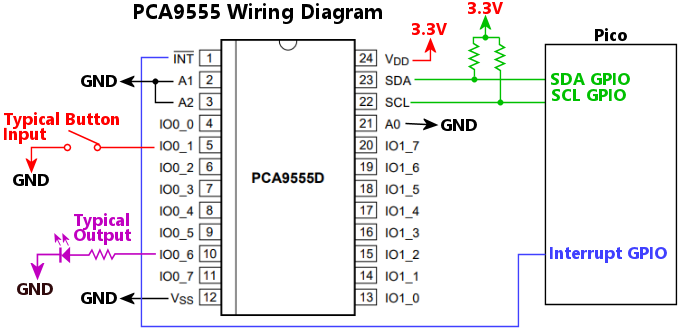
Wiring notes:
The 7-bit I2C address of the chip. The PCA9555's I2C address is configured in the chip's wiring, via its A0/A1/A2 pins. Any address in the range 0x20 to 0x27 can be set in the wiring. Set this property according to the A0-A2 wiring.
The I2C bus number, 0 for I2C0 or 1 for I2C1, where the chip is connected.
Sets the initial output port states. This can be set as an integer giving a bit mask of the on/off states of the ports, or as an array of true/false or 0/1 values.
If expressed as an integer, each bit of the value corresponds to the on/off state of a port (a 0 bit is OFF, a 1 bit is ON). The low-order bit of the value (0x0001) gives the value for port 0_0, and the bits are assigned to ports consecutively in bit order. So port 0_1 is the second bit (0x0002), 0_2 is the third bit (0x0004), and so on, with the high-order bit (0x8000) assigned to port 1_7. This format is obtuse in general, but it has its concise charm for certain cases, such as when you want to set all of the ports to the same level (all OFF is 0x0000, all ON is 0xFFFF), or perhaps if you want to set the whole 1_X block ON and the whole 0_x block off (0xFF00).
If expressed as an array, each element of the array corresponds to one port, starting at 0_0 for the first element, 0_1 for the second element, and so on. For example, to turn all of the 0_X ports OFF and all of the 1_X ports ON, you could write [0,0,0,0,0,0,0,0,1,1,1,1,1,1,1,1]. This is a lot more verbose than the integer format, but much more readable for cases where the values are mixed.
The GPIO port number where the chip's INT (interrupt) line is connected. This is optional; omit if if the interrupt line isn't connected. The software is more efficient if you connect the interrupt line, because the interrupt signal lets Pinscape detect when the input state of the chip has changed without performing an I2C bus transaction, which saves time on unnecessary I2C polling. Note that the chip's interrupt line is specifically designed to be shared among multiple PCA9555 chips, to conserve GPIO ports on the Pico. You can wire the interrupt lines from multiple PCA9555 chips together, connecting them all to a single Pico GPIO port. The Pinscape software specifically recognizes and supports that configuration.
Configures a collection of PCA9685 PWM controller chips. These chips can be used to add PWM output ports to the Pico. This property is given as an array of objects, with each object specifying the configuration for one chip.
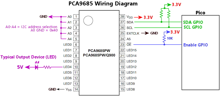 Wiring notes:
The 7-bit I2C address of the chip. The PCA9685's address is set by the wiring to its address pins (A0 to A5), for addresses from 0x40 to 0x78, excluding the reserved address 0x70. Set this property according to the chip's physical A0-A5 wiring.
Sets the "drive mode" for the output ports on the chip:
The PCA9685 does not provide current limiters on the ports in either mode, so current-limiting resistors are required for LEDs.
The I2C bus number, 0 for I2C0 or 1 for I2C1, where the chip is connected.
If true, the output ports use inverted logic: the port output is driven LOW when logically ON, and either driven HIGH or placed in high-impedance state (according to the drive mode) when the port is logically OFF. If false (the default), the port output pin is driven LOW when logically OFF and HIGH/high-impedance when logically ON. Inverted logic mode is usually used in combination with the open-drain drive mode, but that's not a requirement.
The Pico GPIO port number connected to the OE (output enable) pin on the chips.
Alternatively, this can be an object, using the same syntax as outputs[].device. This allows you to connect the OE pin to a GPIO extender such as a PCA9555, saving a GPIO port on the Pico.
This is optional; you should only specify it if the OE pin from the chip is physically wired to the Pico. You can alternatively simply connect the OE pin from the chip to GND, which permanently enables the output ports on the chip.
If you wire the OE pin to a Pico GPIO port (or a GPIO extender port), you should also wire it to VCC through a 10K resistor. This will pull the OE line high throughout the initial power-up process, so that all of the PCA9685 output ports remain disabled until the Pinscape software explicitly enables them.
The advantage of wiring the OE pin to the Pico is that it helps ensure glitch-free startup, by leaving all of the output ports on the PCA9685 in a high-impedance state after power-up until the software has finished initializing the chips. This avoids allowing the ports to activate during the brief window between the Pico CPU reset and the completion of software initialization in the firmware. If OE is hard-wired to GND, all ports will be enabled immediately when the power comes on, so ports might fire briefly before the software initializes them. This can be annoying or even alarming if noisy devices like solenoids are controlled through the ports.
If you have multiple PCA9685 chips, you can connect them all to the same port on the Pico. In that case, you should only define the oe property once, for one of the chips in your configuration (it doesn't matter which one you pick). Pinscape has no need to address the OE pin separately for each chip, since it only operates the port for all of the chips as a group at startup and shutdown, so you can save GPIO ports on the Pico by connecting all of the OE pins together.
Sets up the Pico's on-board ADC, which can read from GPIO ports 26-29 and from the Pico's internal temperature sensor. This configuration entry lets you use the Pico ADC for input from a potentiometer plunger or a joystick input.
Don't include this entry if you're configuring one of the external peripherals that takes over the ADC directly, such as TCD1103 or TSL1410R. Those peripherals need special high-speed access to the ADC that requires them to take full control of the device, which precludes sharing ADC channels with other inputs.
Sets the GPIO input port or ports assigned to the Pico ADC. This can be a single port number or a list of port numbers (e.g., [26, 27]). The only ADC-capable ports are 26, 27, 28, 29, and 30. Port 30 is a pseudo-GPIO that's hard-wired to the Pico's internal temperature sensor. If you provide a list, the ports must be listed in ascending order. The entries in the port list correspond to the ADC channel numbers that you can use in joystick axis and plunger assignment entries: "pico_adc" is the first channel, assigned to the first GPIO in the list; "pico_adc[1]" is the second channel, assigned to the second GPIO in the list; "pico_adc[2]" is the third channel.
Configures the plunger (ball shooter) system. Pinscape lets you set up a physical pinball plunger mechanism as an input to the pinball simulators, using a sensor to monitor the position of the plunger and pass that information to the pinball simulator in real time. A mechanical plunger adds a wonderful element of realism to virtual pinball play, and if you have a good sensor, it nicely replicates the playing experience for plunger skill shots. Pinscape Pico is compatible with all of the sensor types that the original KL25Z Pinscape supported, including imaging sensors, quadrature encoders, IR proximity sensors, and sliding potentiometers.
If true, enables auto-zeroing. True by default. This is only meaningful with sensors that use relative positioning, specifically the quadrature encoder sensor. It's ignored for other sensor types. The point of auto-zeroing is that the quadrature sensors can only detect the distance the plunger has moved since the last reading - they can't detect the absolute position of the plunger. As a result, if the sensor misses any small movements that the plunger makes, its internal notion of the position gets out of sync with the actual physical position. Over time, these small errors accumulate, so the actual position and the sensor's reading of the position get further and further out of sync. Auto-zeroing attempts to correct for that by setting the position back to "zero" - the resting position where the plunger settles when you're not manually pulling or pushing on it - whenever the plunger remains completely stationary for an extended period. Thanks to the spring-loaded design of the plunger, it always comes to rest at roughly the same position when you're not actively applying forces to it, and what's more, it's very hard to hold it perfectly stationary for very long by hand. So it's a very safe bet that the plunger is at the equilibrium position any time it's been still for a while. Auto-zeroing exploits this to wash away any accumulated position errors whenever it observes no movement for a little while.
The auto-zeroing "quiet time" interval, in milliseconds (1000 milliseconds equals one second). The default is 5000 (5 seconds). This sets the amount of time that the plunger has to remain stationary before auto-zeroing takes effect. When the plunger is motionless for this long, Pinscape automatically sets it to the "parking" position, on the assumption that the plunger is at rest at the equilibrium position.
Enables the plunger subsystem. True by default.
Applies to proximity sensors only (VCNL4010, VCNL4020); ignored for other sensor types. This sets the "power law" exponent for converting the analog brightness reading that the sensor measures to plunger distance units. The default is 2, which uses the classic "inverse square" physics formula for the brightness of a distant point source of light, which holds that the brightness varies inversely with the square of the distance. You can change this as needed to optimize the linearity of the distance conversion. The inverse-square law applies to point sources of light, which doesn't quite describe the geometry of the IR proximity sensors. You can experiment with the Config Tool's plunger viewer to check how well the on-screen plunger position tracks the true physical position as you move the plunger through its travel range. Ideally, the on-screen plunger should track the real position linearly - that is, moving the real plunger by a given distance should produce the same on-screen distance change across the whole travel range. If the on-screen plunger moves faster at one end of the range than the other, you can try adjusting the power law exponent up or down to see if that improves the linearity. You can set this an integer or number with a fractional part, such as 2.25.
Sets the sensor that serves as the source of the plunger position reading. In most cases, you can omit this, because the plunger system will automatically choose whichever type of physical plunger sensor device you've configured. In most cases, you'll only attach one such sensor, so there will be no confusion about which one is the plunger input. If for some reason you're using multiple sensors that Pinscape recognizes as plunger inputs, you can use plunger.source to specify which one should actually serve as the plunger input. Set this to a string giving the configuration key for the physical sensor device you want to use, such as "tcd1103" or "aedr8300".
If you configure an ADC device with multiple channels, and you want to use one of those for a potentiometer plunger input, you'll have to set this to specify which channel to use. For the Pico on-board ADC, set this to "pico_adc" to use the first configured channel for the plunger, "pico_adc[1]" to use the second channel, "pico_adc[2]" for the third channel, and so on.
| Source | Description |
|---|---|
| "pico_adc" | Potentiometer plunger connected to the Pico's on-board ADC. This is shorthand for "pico_adc[0]", which makes it convenient for the common case where only one Pico ADC channel is enabled. |
| "pico_adc[n]" | Potentiometer plunger connected to the nth logical channel of the Pico's on-board ADC. Use this form when the Pico ADC is configured with multiple analog inputs enabled - this tells Pinscape which of the input pins is connected to the plunger potentiometer. Logical channels are numbered from 0, and correspond to the inputs enabled in the pico_adc.gpio list. "pico_adc[0]" selects the first gpio list entry, "pico_adc[1]" selects the second entry, and so on. |
| "ads1115" | Potentiometer plunger connected to an ADS1115 ADC chip. This is shorthand for "ads1115_0[0]", which makes it convenient for the common case where only one ADS1115 chip is connected and only one of the chip's input channels is enabled. |
| "ads1115_n[m]" | Potentiometer plunger connected to an ADS1115 ADC chip. This selects logical channel m on the nth chip in the configuration list. n and m are numbered from zero, so "ads1115_0[0]" selects the first logical channel on the first enabled chip. |
| "tsl1410r" | TSL1410R linear imaging sensor. |
| "tsl1412s" | TSL1412S linear imaging sensor. |
| "tcd1103" | TCD1103 linear imaging sensor. |
| "vcnl4010" | VCNL4010 IR proximity sensor. |
| "vl6180x" | VL6180X IR distance sensor. |
Configures the ZB Launch mechanism. ZB Launch lets you use the mechanical plunger as a substitute for a Launch Ball button. Some virtual pin cab builders like to install both of these, but others prefer a cleaner look with just the plunger - that's what most real pinball machines look like, after all. The downside of not installing both is that some tables don't have a plunger at all and just use a launch button, so you don't get the same playing experience with those tables if you don't have a physical Launch Ball button installed. The ZB Launch feature helps fix that by letting you use the plunger almost like a Launch button.
ZB Launch has two elements. The first is a DOF port that lets the PC-side pinball simulator notify Pinscape, by turning on the DOF port, when a plunger-less table is loaded into the simulator. Pinscape uses this signal to enable the ZB Launch feature. The second element a button input to the PC. When ZB Launch is enabled by the DOF signal, Pinscape monitors the plunger position, and converts plunger motion into button presses that it sends to the PC. The button presses simulate the Launch Ball button. Button presses are generated when you either pull back and release the plunger, or just push it forward into the barrel spring. Pushing and holding the plunger is treated as pushing and holding the Launch Ball button.
Sets the button action to perform when the virtual Launch Ball button is pressed. Rather than pointing ZB Launch to one of your actual buttons, this lets you set up what amounts to a whole separate virtual button, just for the ZB Launch features. This property contains an object with exactly the same settings you'd use for an "action" definition in the "buttons" array. For example, the canonical Launch Ball button sends a RETURN key press to the PC, which you can get by writing action: { type: "key", key: "return" }.
The DOF output port number or name for the incoming ZB Launch Mode DOF signal. This must match the port that you assign in the DOF Config Tool. This is optional, because you can more conveniently designate the port directly in the "outputs" section, by setting the port's device type to "zblaunch". Doing that designates the port as a virtual output (not connected to a physical output port) that sets the ZB Launch mode.
The length of the Launch Ball button pulse, in milliseconds, applied when you pull back and release the plunger. That gesture generates one press on the simulated Launch Ball button, with the duration of the press set by this parameter.
The plunger position threshold where the Launch Ball button is activated by pushing the plunger forward. This must be a negative number between -1 and -32768. When the plunger is pushed beyond this line, and ZB Launch mode is in effect, Pinscape simulates pressing the Launch Ball button. The default value is -2600, which is about half of the full forward travel range. You can use the Plunger Setup window in the Config Tool to map out the readings your plunger produces at various positions and use that to figure an optional threshold setting. The plunger viewer also shows you the ZB Launch processing in real time, so you can test out the effects of different settings.
Configures PWM options for Pico GPIOs that are used as PWM outputs.
Sets the default PWM frequency (in Hertz) for Pico GPIO ports that are used as GPIO outputs. The default is 20000, which was chosen because it's high enough to be out of the human hearing range, so it shouldn't produce any audible noise if a GPIO is used to drive a mechanical device. Motors and solenoids have a tendency to vibrate at the PWM frequency when controlled via PWM, which can produce acoustic noise at the same frequency. If this is in the audible range of human hearing - anywhere from about 40 Hz to 20 kHz - it can produce annoying buzzing or whining noises. Frequencies above 20 kHz are too high for most people to hear, so even if we can't eliminate the vibration, we can at least make it so high-pitched that you can't hear it. Your dog might still find it annoying, though. 20000 Hz is also low enough that it shouldn't pose a problem for external amplifier circuitry, such as optocouplers and MOSFETs. GPIOs that control physical devices generally have to be connected through amplifier circuits, and many of those can only handle a limited range of PWM frequencies. 20 kHz is within the tolerable range for typical circuits used for this purpose.
This configures an external RGB status LED that displays Pinscape's real-time status with different colors and blinking patterns. This is a carryover from the KL25Z version of Pinscape, which took advantage of the KL25Z's built-in RGB LED to display system status. The Pico only has a monochrome LED, and Pinscape does what it can to display a little bit of the same status information there, but it's a pretty impoverished information channel compared with the full-color LED of the KL25Z. So Pinscape Pico lets you add an external RGB LED. This is optional (and frankly a little frivolous), since you can get vastly better status information from Pinscape Pico via its message log system, but the RGB status light is still a nice little bonus feature if you have the GPIO ports to spare for it.
Sets the polarity of the LED. Set this to "low" if the LED's negative terminals (cathodes) are wired to the GPIO ports. Set it to "high" if the LED's positive terminals (anodes) are wired to the GPIO ports. Most RGB LEDs use the "common anode" configuration, where all of the color channels are wired to a single positive voltage supply through a single pin, and the cathodes (the negative terminals) are wired individually to the GPIO ports. That's the "active low" configuration, and it's the default if you omit this property, since it's the most common configuration. Note that this is something that's designed into the LED itself, so it's not a choice you have to make when doing the wiring, but rather just a feature of the LED that you have to determine from the LED's data sheet.
The GPIO port number attached to the blue channel of the status LED.
This optional property lets you configure the color mix formulas for the various primary and secondary colors that the Pinscape software displays via the status LED. Pinscape uses the standard RGB color-space formulas by default, but many RGB LEDs have such unbalanced intrinsic brightness levels for their color elements that the standard formulas don't end up looking anything like the colors they're meant to display. To fix this and get more accurate color rendition, Pinscape lets you specify the actual formula to use for each primary color. You can set all of these, none of these, or any subset; anything you don't set will use the built-in default formula.
For each element, you can use one of the following formats:
Note that the status LED uses a coarse-grained PWM control that only allows for 16 gradations of brightness in each channel. This means that the three-digit HTML style "#RGB" formula is really all that you need to specify the colors. Despite this, the full six-digit format is accepted, and the range for the numeric format is 0 to 255 for each color, but levels are rounded to the nearest multiple of 16. The coarse PWM control is used because it avoids using any native Pico PWM channels, which are a limited resource that we'd prefer to leave available for other uses. The status light doesn't need such a mix rich of colors that it justifies tying up the resources. (In fact, the original KL25Z version of Pinscape didn't use PWM colors at all, so it could only show the basic primary and secondary colors; the Pico version's coarse-grained PWM lets its show a few extra colors, such as orange.)
Sets the RGB color mix for blue displays on the status LED.
Sets the RGB color mix for cyan displays on the status LED.
Sets the RGB color mix for green displays on the status LED.
Sets the RGB color mix for orange displays on the status LED.
Sets the RGB color mix for red displays on the status LED.
Sets the RGB color mix for violet displays on the status LED.
Sets the RGB color mix for white displays on the status LED.
Sets the RGB color mix for yellow displays on the status LED.
The GPIO port number attached to the green channel of the status LED.
The GPIO port number attached to the red channel of the status LED.
Configures an RV-3032-C7 calendar/clock chip, which allows the Pico to keep track of the current date and time across resets and power cycles. Assuming that the chip is outfitted with a battery as a back-up power supply, the chip will keep track of the time and date even when the Pico is unpowered.
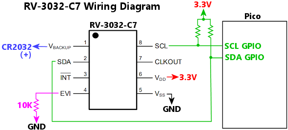 Wiring notes:
The I2C bus number, 0 for I2C0 or 1 for I2C1, where the chip is connected. This chip has a fixed I2C address, so you only have to specify the bus number; there's no need to specify the address.
Configures the Pico's two types of serial ports, which allow the Windows host to communicate with the Pico via a text terminal interface. The terminal can be used to view log messages and to connect to a primitive command console on the Pico, which lets you access a number of internal testing and diagnostic functions that can be useful for advanced troubleshooting.
You don't have to enable the Pinscape serial ports to use any of Pinscape's virtual pin cab features, or to access the device through the Pinscape Config Tool. Pinscape uses separate USB interfaces for all of the pin cab functions. The serial ports are only needed if you want to connect to the Pico's command console for debugging or troubleshooting purposes, or if you want to use it to monitor the message log.
In order to use the serial ports from Windows, you'll need a terminal program. The most popular one among software developers (who are practically the only people who use terminal programs at all these days) is probably PuTTY, which is free and open-source. Almost everyone who uses PuTTY uses it to connect to remote Linux servers, but it's also great for talking to the Pico.
You'll have to figure out the COM port number that Windows assigns to the Pinscape connection. Pinscape has no control over this; Windows is solely responsible for choosing the port number. For the USB virtual COM port, the Config Tool's Overview page displays the assigned COM port number. If you're using the Pico UART port and plugging it into a physical serial port on your PC, use the physical COM port number for the physical serial port where you plugged in the cable. This is almost always COM1, unless you have more than one, in which case they'll be numbered sequentially - COM1, COM2, etc. If you're using a Pico UART port, but plugging it into the PC through a USB-to-UART adapter cable, the COM port number is the one that Windows assigned to the adapter. You should be able to identify that by opening Device Manager and scanning the "Ports (COM & LPT)" section.
Once you know the COM port number, set it up in PuTTY by setting Connection Type to Serial, typing in the COM port number in the Serial line box, and setting Speed to 115200.
Configures the Pico's UART serial port. The UART port sets up a pair of GPIO pins on the Pico as a physical serial port, which you can connect through an adapter to a physical COM port (a 9-pin serial port) on your PC.
An adapter is required to shift the PC's COM port voltage level to the Pico's 3.3V logic level. Search online for "RS-232 3.3V GPIO adapter".
The adapter should plug directly into the PC's 9-pin COM port, and should provide four output pins, usually labeled TX, RX, GND, and VCC (or 3.3V). Connect to the Pico as follows:
| Adapter Pin | Pico Pin |
|---|---|
| TX | GPIO port you designated as RX |
| RX | GPIO port you designated as TX |
| GND | GPIO port you designated as GND |
| VCC | Do not connect |
If you don't have a physical 9-pin serial port on your PC, you can still use the Pico UART connection, by connecting it to a PC USB port through a USB-to-UART adapter. There are some advantages to doing this instead of using the "virtual" COM port over the Pico's main USB connection, but also the drawback that it requires another adapter. In this case, the thing to search for is a "USB 3.3V UART adapter". The wiring on this type of adapter should be exactly the same as shown above; the only difference is that this adapter plugs into a USB port on the PC rather than a 9-pin COM port.
The UART port and the virtual USB COM port serve exactly the same purpose, so you don't usually need both. In fact, you don't need either one; serial port access is mostly just a convenience for troubleshooting, since it lets you easily access the Pinscape message log and command console. Troubleshooting is, we hope, something that you won't have to do very much of, and even then only when you're initially setting up your system. If all goes well, you shouldn't need a serial port at all, since you should be able to do everything necessary to set up the system through the Pinscape Config Tool.
If you do want to set up a COM port, the USB virtual COM port is the easier of the two to set up, because it doesn't require any extra cabling and doesn't take up any GPIO ports. The UART COM port does have one nice advantage, though: because it's a physical serial connection, it doesn't get "dropped" when the Pico reboots, so you can just connect a terminal window and leave it open forever (or until you reboot Windows, anyway). The USB connection, in contrast, does get dropped every time the Pico reboots, so you have to manually restart the terminal session on each reboot. The UART COM port is more work to set up, but it doesn't suffer from the reboot issue. If you're planning to do development work on the Pinscape C++ firmware, the UART setup is definitely the way to go; otherwise, you'll probably be perfectly happy with the virtual USB COM port.
Sets the baud rate (bits per second) for the UART connection. The default is 115200, which is the highest speed typically allowed on the PC side. If you change this, you must also set the rate to match in your terminal program on the PC.
Configures the command console on the UART port. If this is omitted, the console is enabled by default.
Sets the text output buffer size for the console, in bytes. The buffer is needed to hold text temporarily while it's being sent through the UART connection, because the UART connection is fairly slow compared to how quickly the Pico can generate text. The default is 8192 bytes.
If true, enables the command console on the UART. True by default.
Sets the size of the command history buffer, in bytes. This buffer holds a history of recent commands that you typed, so that you can recall them to repeat or edit (recall a command by pressing the UP arrow, repeat to recall older commands).
If true, logging is enabled on the UART port; this is the default if the port is configured at all. Set this to false to disable logging on this port.
Sets the GPIO port for the RX (receive) connection to the UART. This must be one of 1, 5, 9, 13, 17, 21, 25, or 29, since those are the only GPIO ports on the Pico capable of serving as UART RX ports. In addition, this port must be on the same UART unit (UART0 or UART1) as the TX port. If the TX port is 0, 12, 16, or 28, you're using UART0, so RX must be one of 1, 13, 17, or 29. If the TX port is 4, 8, 20, or 24, you're using UART1, so the RX port must be 5, 9, 21, or 25.
Sets the GPIO port for the TX (transmit) connection to the UART. This must be one of 0, 4, 8, 12, 16, 20, 24, or 28, since those are the only GPIO ports on the Pico capable of serving as UART TX ports.
Configures the USB virtual serial port (also known as a "CDC" port). This works just like the UART serial port, but it doesn't require any GPIO ports on the Pico, and it doesn't require any special cabling, because it runs over the Pico's main USB cable alongside all of the other USB communications. You also don't need any special device driver setup if you're using Windows 10 or later, since Windows 10 and 11 include built-in USB CDC drivers. If you're Windows 8 or earlier, you might need to install a device driver; search for "USB CDC driver" for your operating system version.
The USB COM port is disabled by default. To enable it, simply include this object in the JSON configuration. To connect to the port, you'll need a terminal program on the PC, such as PuTTY. Get the COM port number from the Config Tool's Overview page - it will be listed in the USB Interfaces section. Go to PuTTY, set the Connection Type to Serial, type the COM port number into the Serial Port box, and set the speed to 115200.
Note that the USB COM port is purely optional! You don't have to set this up to configure Pinscape or to use Pinscape with any of the pinball players. The COM port is just there to let you view the message log and access the command console. It's not a necessity - it's more of a troubleshooting aid, and more for power users who are comfortable working with command lines and terminals.
Configures the command console on the USB COM port. If this is omitted, the console is enabled by default.
Sets the text output buffer size for the console, in bytes. The buffer is needed to hold text temporarily while it's being sent through the USB COM port, because the Pico can generate text faster than the USB conection can pass it to the PC. The default is 8192 bytes.
If true, enables the command console on the USB COM port. True by default.
Sets the size of the command history buffer, in bytes. This buffer holds a history of recent commands that you typed, so that you can recall them to repeat or edit (recall a command by pressing the UP arrow, repeat to recall older commands).
If true, enables logging on the USB COM port. True by default.
Configures a TCD1103 linear imaging sensor. This sensor can be used as a plunger position sensor. See the Pinscape Build Guide for setup instructions.
The TCD1103 interface requires exclusive access to the Pico's on-board ADC, so you can't also configure the pico_adc device when a TCD1103 is present.
The Pico GPIO port number connected to the sensor's FM (master clock) pin.
The Pico GPIO port number connected to the sensor's ICG (integration clear gate) pin.
Set this to true if there's a logic inverter chip wired between the chip's logic inputs (FM, ICG, SH) and the Pico GPIO ports. The chip's data sheet recommends using a logic inverter because of the relatively high capacitance of the chip's input gates, which some microcontrollers can't drive at the high clock speeds required. This property is true by default, since this is the recommended hardware configuration. Set it to false if the chip's logic inputs are connected directly to Pico GPIO ports with no logic inverter.
The Pico GPIO port number connected to the sensor's OS (analog pixel output) pin. This must be one of the Pico's ADC capable pins, GPIO 26, 27, or 28. Note that the OS pin shouldn't be connected to the Pico GPIO port directly; the chip's data sheet recommends a transistor circuit between the OS port and the ADC input, because the output signal from the chip is too weak for most ADCs to read directly.
The Pico GPIO port number connected to the sensor's SH (shift gate) pin.
Configures a collection of TLC59116 PWM controller chips. These chips can be used to add PWM output ports to the Pico. The tlc59116 property is defined as an array of objects, with each object defining the configuration of one connected TLC59116 chip.
There are several variations of the TLC59116 with different letter suffixes, such as TLC59116IPWR, TLC59116F, TLC59116IRBHR. These differences are important when you're buying chips to fit a particular circuit board design, because the subtypes vary in physical size, pin layout, and electrical interface. Always be sure that you're ordering and installing exactly the variant of the chip that your circuit board design calls for. Despite those hardware differences, the variants all have the same software interface, so the Pinscape configuration uses the tlc59116 property no matter which variant of the chip you're using.
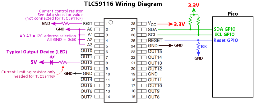 Wiring notes:
The 7-bit I2C address of the chip. The TLC59116's I2C address is set by the wiring to its address pins (A0 to A3). It can be set to addresses from 0x60 to 0x6f, excluding the reserved addresses 0x68 and 0x6B. Set this property according to the chip's physical A0-A3 wiring.
The I2C bus number, 0 for I2C0 or 1 for I2C1, where the chip is connected.
The GPIO port number connected to the chip's RESET pin. Omit this if the RESET pin isn't connected to the Pico (in which case it should be hard-wired to 3.3V through a 10K resistor).
Connecting the RESET pin allows the Pico to perform a hardware reset on the chip under software control, which Pinscape uses to reset the chip during startup. This can be helpful to clear any fault conditions on the chip without the need to power-cycle the whole system.
Configures a daisy-chain of TLC5940 PWM controller chips. These chips can be used to add PWM output ports to the Pico. The chips can be connected together in a daisy chain, which lets you connect multiple instances of the chip without any additional GPIO ports beyond those needed to connect the first chip.
If necessary, you can configure multiple TLC5940 daisy chains, each with its own set of GPIO ports. There should be little reason to do so in practice, since you can instead just connect more chips to the same chain. But if you do set up multiple chains, define this property as an array of objects, with each object defining one daisy chain.
There are several variations on the TLC5940, with various letter suffixes: TLC5940NT, TLC5940PWR, TLC5940RHBR, TLC5940PWP. These are all packaging variations - differences in the size of the chip and the pin layout - so it's important to buy the exact type required if you're sourcing parts for a particular circuit board layout. But the JSON configuration is the same for all of them, since they all work the same way at the software level.
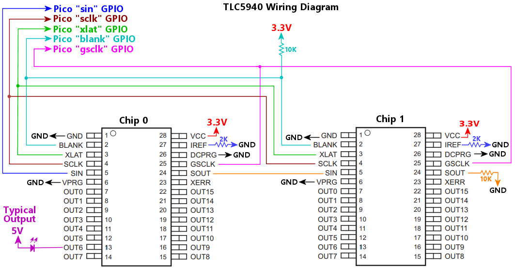 Wiring notes:
The Pico GPIO port number connected to the chip BLANK pins. This must be connected to the BLANK pins for all of the chips in the chain.
"Dot correction" data. This is an array of integers, from 0 to 63, that adjusts the PWM duty cycle of each port individually. This is an adjustment that's applied on top of the live value set by DOF or other sources. Its purpose is to compensate for slight differences in the native brightnesses of the individual pixels when the chip is driving a dense pixel array, such as a dot matrix display. Setting a port's DC level to 63 runs the port at full brightness; lower values slightly reduce the brightness. The idea is that you'd adjust brighter pixels downwards until all pixels look the same when driven at the same nominal duty cycle.
This is only used if you connect the DCPRG and VPRG pins from the chips to Pico GPIO ports. In a Pinscape setup, those pins are normally simply connected to GND, which leaves all of the output ports at full brightness by default, with no dot-correction adjustments. Any dcData array is ignored in that case. It's unlikely that dcData wlil be needed in any virtual pin cab setups, but capability is there if needed.
The Pico GPIO port number connected to the chip DCPRG pins. This is optional; if connected, connect it to the DCPRG pins for all of the chips in the chain. If it's not connected to a GPIO port, simply connect all of the DCPRG pins to GND; that's the normal way to connect it in a Pinscape setup. The purpose of the DCPRG pin is to enable "dot correction", which is a feature of the chips designed for applications where the chips are driving dense pixel arrays, where small differences in the native brightnesses of adjacent pixels might be bothersome. In a Pinscape setting, the chips usually drive a diverse collection of devices that wouldn't benefit from dot correction, so this pin is usually left unconnected rather than taking up another GPIO port.
The Pico GPIO port number connected to the chip GSCLK pins. Connect this port to the GSCLK pins for all chips in the chain. This GPIO port must be the next higher port number after the SCLK port. For example, if SCLK is on GPIO 17, GSCLK must be on GPIO 18.
The number of TLC5940 chips connected to the daisy chain. This is required so that the software knows how many port settings to send to the chain on each update cycle.
The PWM frequency, in Hertz (cycles per second). The default is 200; this can be set from 1 to 7324 Hz (the upper bound is a hardware limit of the chip). When the chip is driving LEDs, the frequency affects visible flicker; anything above about 200 Hz should eliminate any flicker. When the chip is driving mechanical devices (motors and solenoids), the PWM frequency sometimes interacts with the mechanisms to cause acoustic vibration at the PWM frequency, which can be audible as buzzing or whining sounds. Adjusting the PWM frequency can often mitigate this. The PWM frequency can only be adjusted across the whole chain (it can't be set individually per port).
The Pico GPIO port number connected to the chip SCLK pins. Connect this port to the SCLK pins for all chips in the chain.
The Pico GPIO Port number connected to the first chip's SIN pin. This GPIO port connects only to the SIN pin of the first chip in the chain. For each subsequent chip in the chain, connect SIN to the previous chip's SOUT (the second chip's SIN connects to the first chip's SOUT, the third chip's SIN connects to the second chip's SOUT, etc).
The Pico GPIO port number connected to the chip VPRG pins. This is optional; if connected, connect it to the VPRG pins for all of the chips in the chain. If it's not connected to a GPIO port, simply connect all of the VPRG pins to GND. This pin works with DCPRG to enable dot correction, which isn't normally needed in a virtual pinball setting.
The Pico GPIO port number connected to the chip XLAT pins. Connect this port to the XLAT pins for all chips in the chain. This GPIO port must be the next higher port number after the BLANK port. For example, if BLANK is on GPIO 15, XLAT must be on GPIO 16.
Configures a daisy-chain of TLC5947 PWM controller chips. These chips can be used to add PWM output ports to the Pico. The chips can be connected together in a daisy chain, which lets you connect multiple instances of the chip without any additional GPIO ports beyond those needed to connect the first chip.
If necessary, you can configure multiple TLC5947 daisy chains, each with its own set of GPIO ports. There should be little reason to do so in practice, since you can instead just connect more chips to the same chain. But if you do set up multiple chains, define this property as an array of objects, with each object defining one daisy chain.
The TLC5947 has a fixed PWM frequency of 967 Hz.
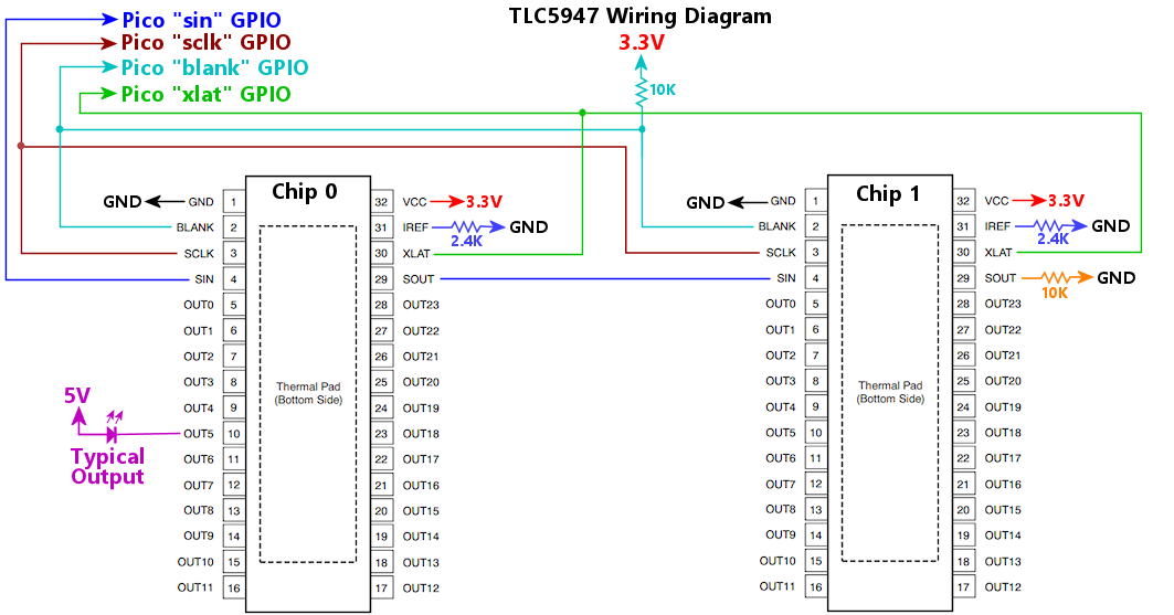 Wiring notes:
The Pico GPIO port number connected to the chip BLANK pins. Connect this port to the BLANK pins for all of the chips in the chain.
The number of TLC5947 chips connected to the daisy chain. This is required so that the software knows how many port settings to send to the chain on each update cycle.
The Pico GPIO port number connected to the chip SCLK pins. Connect this port to the SCLK pins for all chips in the chain.
The Pico GPIO Port number connected to the first chip's SIN pin. This GPIO port connects only to the SIN pin of the first chip in the chain. For each subsequent chip in the chain, connect SIN to the previous chip's SOUT (the second chip's SIN connects to the first chip's SOUT, the third chip's SIN connects to the second chip's SOUT, etc).
The Pico GPIO port number connected to the chip XLAT pins. Connect this port to the XLAT pins for all chips in the chain. This GPIO port must be the next higher port number after the BLANK port. For example, if BLANK is on GPIO 15, XLAT must be on GPIO 16.
Configures a TSL1410R linear imaging sensor. This sensor can be used as a plunger position sensor; see the "old" KL25Z Pinscape setup instructions for details. Note that there are two variations on this chip: the TSL1410R and TSL1412S. They're basically the same chip except with slightly different pixel file sizes. If you're configuring a TSL1410R, use the "tsl1410r" key in the JSON configuration; if you're configuring a TSL1412S, use the "tsl1412s" key. Everything else is identical between the two chips.
The TSL1410R interface requires exclusive access to the Pico's on-board ADC, so you can't also configure the pico_adc device when a TSL1410R is present.
The GPIO port number where the chip's CLK (serial clock) pin is connected.
The GPIO port number where the chip's SI (serial input) pin is connected.
The GPIO port number where chip's SO (serial output) pin is connected. This must be one of the Pico's ADC-capable GPIO ports, GPIO 26, 27, or 28.
Configures a TSL1412S linear imaging sensor. This sensor can be used as a plunger position sensor; see the "old" KL25Z Pinscape setup instructions for details. Note that there are two variations on this chip: the TSL1412S and TSL1412S. They're basically the same chip except with slightly different pixel file sizes. If you're configuring a TSL1412S, use the "tsl1412s" key in the JSON configuration; if you're configuring a TSL1412S, use the "tsl1412s" key. Everything else is identical between the two chips.
The TSL1412S interface requires exclusive access to the Pico's on-board ADC, so you can't also configure the pico_adc device when a TSL1412S is present.
The GPIO port number where the chip's CLK (serial clock) pin is connected.
The GPIO port number where the chip's SI (serial input) pin is connected.
The GPIO port number where chip's SO (serial output) pin is connected. This must be one of the Pico's ADC-capable GPIO ports, GPIO 26, 27, or 28.
Configures the TV ON feature, which can send commands to turn on your TVs/monitors during the power-on startup sequence. This is useful if you're controlling power to your TVs through a switching power strip that switches everything off when the computer is off, and the TVs don't automatically turn on again when power is restored. Some TVs turn on as soon as they're plugged in, but many just go into standby mode.
The TV ON system relies on a custom power-sensing circuit that you have to add to the Pico. The circuit is built into the Pinscape Expansion Boards, and you can also build it separately by following the plans in the Pinscape Build Guide.
The circuit requires two input port connections to the Pico, which can be connected directly to Pico GPIO ports, or to ports on peripheral devices that the button and output subsystem can read and write. For the "sense" input port, supported chips include PCA9555 and 74HC165; for the "set" output port, PCA9555, PCA9685, and 74HC595 can be used. This allows the power sensor to be used without tying up any Pico GPIO ports.
The Pinscape software monitors the power sensor through the "sense" input port, and when it sees that the system power has switched from OFF to ON, Pinscape can do two separate things to activate your TVs. First, it can pulse a relay that you've hard-wired to your TV's ON switch. This approach isn't recommended because it requires invasive surgery on your TV, including opening the outer case and soldering wires to the TV's power button, which all runs a big risk of damaging your TV. The second approach is much safer and easier: control the TV through its IR remote receiver. Pinscape can send a series of IR remote control commands through its IR transmitter when the power sense circuit triggers the TV ON event. You can program this with whatever commands are needed needed to power up your TV. You can send any number of IR commands this way, so you can use it to power up multiple TVs, and also to send any extra commands needed to set modes on the TVs and select input sources.
This sets up the sequence of IR commands to send during the power-up sequence. This is given as an array, with the series of commands to send in order. Each entry can be either a string containing a command code, or a number giving a delay time in milliseconds. Delay times let you pause between commands as needed - some TVs might not be ready to accept the next command right away, especially after just powering on, so this lets you insert some delay time as needed.
Command strings are given in the Pinscape universal IR code format. The easiest way to determine the command string for a particular remote control button is via the Config Tool's IR & TV ON window, which shows command codes that are received on the IR sensor as they come in. Open the IR window, then point your remote control at the Pinscape receiver and press the button you want to identify. The command code should appear in the list in the IR window. This uses the same format needed here, so you can simply copy and past the code from the IR window into the config file. When "learning" a command code, be sure to hold the remote control button down long enough to trigger auto-repeat, since many IR protocols have special coding for repeats that Pinscape will only be able to detect if you actually force the remote to transmit the key in repeat mode.
You can prefix any command code with a repeat count, of the form "number*". For example, "5*01.02.04FB1AE5" sends the code 5 times. Most consumer remotes send several repeats for each key press as a matter of routine, probably in part because IR isn't a very reliable communication channel, and blasting repeats is one way to improve the odds of the message getting through. You might find it useful in some cases to employ the same strategy, which is why we include the repeat-count option here.
Sets the startup delay time, in milliseconds (1000 milliseconds equals one second). The default is 7000 (7 seconds). This is the amount of time that the TV ON system waits between detecting a power-up event through the power sensing circuit, and initiating the TV relay and IR commands to turn on the TVs. The reason that a delay is needed is that most TVs need a few seconds after they're plugged in before they'll pay any attention to button presses or IR commands. The delay is designed with this in mind, to give the TVs time to initialize before Pinscape starts sending commands. The actual amount of time needed varies from one TV to the next, so you'll need to experiment with your devices to find the optimal time. If you find that the TVs aren't reliably turning on in response to the Pinscape commands, you can try increasing the delay time.
This object sets up the GPIO connections for the special external power-sensing circuit that the TV ON system relies on. This is required to use the TV ON feature.
The GPIO port number for the power-detect circuit's "sense" input, or an input port object following the syntax used to define a button source. If an object is used, and the active property isn't specified, the default is active-high, since that matches the reference power-sense circuit.
The output port for the power-detect circuit's "set" line. This can be a number naming a Pico GPIO port, or it can be an object following the same syntax used to define an output device for a DOF port. The object syntax lets you wire the connection to a GPIO extender chip such as a PCA9555.
If you're using the mechanical relay option to turn on the TV, this sets up the relay connection. This is an alternative to using IR commands to power up the TV at system startup, and it assumes that the TV is equipped with a hard-wired On/Off pushbutton that toggles the TV between standby mode and ON. To use this option, it's necessary to do a little surgery on the TV to physically connect your own wiring to the On/Off pushbutton, so that you can connect these wires to the TV relay. This will usually require opening the TV's outer casing, so it's not something to undertake lightly; the IR remote control option is preferable for most people. If you do decide to use the hard-wired approach, you can find some advice in the Pinscape Build Guide under TV On Switch > Wiring the TV switch.
Sets the relay mode. If not set, the default is "pulse". The valid modes are:
| Mode | Description |
|---|---|
| "pulse" | The default setting. Pulse the relay at system power-up (after the initial delay timer), for the time set in the pulseTime property. This mode is designed for TVs with ON/OFF toggle buttons, where you want to simulate pushing the button (by pulsing the relay to momentarily close the switch) when the system starts up, thereby turning on the TV. |
| "switch" | Switch the relay on at system startup (after the initial delay timer), and leave it on as long as system power is on. This is designed for setup where the relay directly controls power to the TV, and you want to connect the TV power when the system powers up. Most people handle this case by plugging the TV into a switched or "smart" power strip that's controlled by the main PC, but it might be more convenient to use a Pico-controlled relay in a setup that doesn't include a switched power strip. |
| "manual" | The relay is controlled only through commands sent from the host (via the Config Tool, or via custom software using the Pinscape Pico API). No automatic relay action occurs at power-on. This might be useful if you want to keep your physical setup simpler by omitting the power-sensing circuit; you can let Windows control the TV by sending commands from batch scripts when the system starts up. |
This sets the hardware output port for the TV relay. It can be a number naming a Pico GPIO port, or an object using the same syntax as an outputs[].device entry. For example, if the relay is connected to a PCA9555 port, you'd set this up like this: port output:
  {
    tvon: {
      relay: {
        port: { type: "pca9555", chip: 0, port: "IO1_3" },
      },
    },
  }
There's another way to set up the relay output port, if you prefer, which is to configure the port as a regular DOF output in the outputs section, and set the port's source property to "tvon".
Sets the pulse time for the TV ON relay. This is the time that the relay pulses on during the power-up sequence, given in milliseconds (1000 milliseconds equals one second). The default is 250, which is a quarter of a second. The goal is to make the pulse long enough for the TV to notice it, but not so long that the TV thinks it should turn on and then back off again because you're repeating the button. Something on the order of 250 to 500 milliseconds works in most cases, but you might have to experiment to find the ideal setting for your TV.
Configures the USB connection, particularly the USB device identifiers, known as the VID (vendor ID) and PID (product ID). Together, these two 16-bit integers form an identifier that is intended to identify a device uniquely among all USB devices, across all time and space, for the whole of the known universe. To ensure this degree of uniqueness, the VID/PID for any given device is meant to be issued by a central authority, USB-IF, which manages the USB standards and specifications. In practice, many devices - especially open-source projects like this one, but also a fair number of commercial devices from smaller vendors - use ad hoc VID/PID codes that weren't official assigned, because USB-IF charges a rather substantial fee for registration. This makes it possible that some devices are using the same VID/PID codes without knowing it, which might create a conflict with Windows drivers if you simultaneously plug in two devices whose developers happened to pick the same codes.
Which brings us to the whole reason that Pinscape Pico makes the VID/PID codes configurable: to let you resolve any conflicts that the default codes create in your system. All of the Pinscape Pico USB interfaces are discoverable on the Windows side independently of the VID/PID codes, so you can basically set these codes to any values you want without disrupting any Windows software that accesses the Pinscape system. That makes it safe to change the VID/PID settings as needed in the rare case where they create a conflict with another device. In the absence of such a conflict, it's better to leave well enough alone, lest you create a conflict by accidentally choosing a VID/PID that some other device in your system is already using. How would you know if you have a conflict? You probably have a conflict if plugging in Pinscape Pico makes some other device stop working, or if it awakens some non-Pinscape program on your system that mistakes the Pico for some entirely different kind of device. In either of those cases, changing the VID/PID codes on the Pinscape unit should resolve it.
Sets the USB "PID", or product ID, that Pinscape Pico announces when it connects to the PC host. This works with the VID to tell the host what kind of device this is. Like the PID, you shouldn't change this unless you have a conflict with some other device that uses the same VID/PID combination that Pinscape Pico uses by default.
Sets the USB "VID", or Vendor ID, that Pinscape Pico announces when it connects to the PC host. The PC operating system uses the USB identifiers to figure out what kind of device it's talking to. The only reason you should change this is if you're experiencing a conflict that you've isolated to the device identifiers - in other words, there's some other device in your system that's using the same VID/PID combination that Pinscape Pico uses by default. That really should never happen, because Pinscape Pico uses a VID/PID combination that's uniquely reserved for its use, so you should carefully double-check your findings if do suspect such a conflict.
Configures a VCNL4010 IR proximity sensor. This sensor can be used as a plunger position sensor. Refer to the setup instructions in the Pinscape Build Guide.
The I2C bus number, 0 for I2C0 or 1 for I2C1, where the chip is connected. This chip has a fixed I2C address, so you only have to specify the bus number; there's no need to specify the address.
The GPIO port number where the chip's interrupt pin is connected. Omit this if the interrupt pin isn't connected. It's preferable to connect the interrupt pin, since it allows the Pico to tell when a new reading is available without unnecessary I2C polling.
Sets the IR emitter current, in milliamps; this can be set from 10 to 200 in increments of 10. The default is 200. The emitter current is a factor in the sensor's maximum range, with higher currents giving it more range. The sensor is at the limit of its range when used as a plunger sensor, so you normally need to turn this up to the maximum setting of 200 to get decent results, which is why it's the default.
Configures a VL6180X IR distance sensor. This sensor can be used as a plunger position sensor, by following the setup notes in the Pinscape Build Guide.
The Pico GPIO port number where the chip's GPIO0/CE (Chip Enable) pin is connected to the Pico. This is optional; omit it if the pin isn't connected. Connecting the pin allows the Pinscape software to perform a hardware reset on the chip whenever the Pico reboots, which isn't necessary, but might improve reliability by allowing the Pico to clear up any error condition on the chip via the reset.
The I2C bus number, 0 for I2C0 or 1 for I2C1, where the chip is connected. This chip has a fixed I2C address, so you only have to specify the bus number; there's no need to specify the address.
The Pico GPIO port number where the chip's GPIO1/INT (Interrupt) pin is connected to the Pico. This is optional; omit it if the pin isn't connected. Connecting the pin allows the Pico to read the chip more efficiently by avoiding unnecessary I2C polling, since the Pico can tell when a new sample is available without an I2C transaction.
Configures a collection of auxiliary Picos running PWMWorker. PWMWorker is a separate Pico firmware program, provided with the Pinscape Pico software suite, that turns a Pico into a sophisticated PWM Controller chip. You can use a PWMWorker Pico in place of a more mainstream PMW chip like TLC59116 or PCA9685. The big advantage of using a Pico as a PWM controller is that Picos are easy to incorporate into a DIY system, since they don't require soldering any fine-pitch SMD chips. PWMWorker also has some special features that ordinary PWM chips don't have, such as high-resolution gamma correction, configurable PWM frequency, and built-in Flipper Logic protection on output ports (so that the Flipper Logic time limits are enforced even if the main Pinscape unit crashes or malfunctions - it's an added layer of fail-safe reliability). A Pico running PWMWorker can provide 24 PWM-controlled output ports through the Pico's GPIO pins.
Like all I2C devices, each PWMWorker Pico attached to the same bus must have a unique I2C address (unique among PWMWorkers as well as unique among all of the other chips sharing the bus). When you first install the PWMWorker firmware onto a new Pico, it uses address 0x30 by default. You can change a PWMWorker's address to any other valid I2C address by running a Windows program, SetPWMWorkerAddr, that's included with the PWMWorker firmware. The new address is stored in the Pico's flash memory, separately from the firmware, so the Pico will remember its new address even if you update the PWMWorker firmware later. You can change the address again at any time by re-running the SetPWMWorkerAddr program.
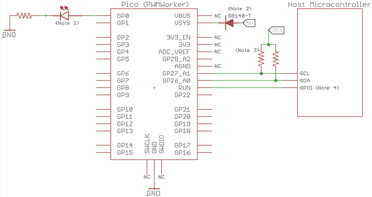 Diagram footnotes:
Pico GPIO ports can directly drive about 10mA. To control a higher-current device, the Pico GPIO output can be used as the control signal input to an amplifier/booster circuit that switches the target device. See the PWMWorker data sheet for examples.
The I2C address assigned to the PWMWorker Pico. The default address when you first install the PWMWorker firmware is 0x30, but you can change this to any other valid I2C address by running the SetPWMWorkerAddr program from a Windows command prompt. Every device sharing an I2C bus must have a unique address, so you'll have to change the address away from the default for each additional PWMWorker you add to the same system. It might also be necessary to change the default address if it happens to conflict with some other I2C chip you're using.
The I2C bus number, 0 for I2C0 or 1 for I2C1, where the PWMWorker Pico is connected.
Sets the initialization timeout, in milliseconds. This sets an upper limit for how long the Pinscape firmware will wait during initial startup for the Worker Pico to respond to commands. Depending on your hardware setup, the main Pico might finish powering up before the Worker Pico does, in which case the main Pico might start sending I2C commands to the Worker Pico before the Worker Pico is ready to respond to them. This timeout specifies how long the main Pico should be willing to wait. The default timeout is 20 ms.
To determine if this might help, you can try resetting the main Pico without interrupting power to either Pico. If Worker Pico initialization succeeds under these conditions, the problem is likely the boot delay. If initialization always fails, even when the power is steadily on the whole time, the problem lies elsewhere, either in the configuration or physical wiring between the two Picos.
Before increasing the wait time, you should first make sure that both Picos are receiving power from the same source. This will make it more likely that both devices boot up at the same time, reducing the need for a longer delay.
Sets the PWM frequency to use for the PWMWorker's output ports, in Hertz. This can be set to any value from 8 to 65535. The default is 20000 Hz.
This is the overall refresh frequency, which sets how many times per second an output is blinked on. PWM controls the apparent brightness of an LED (or the power level delivered to other types of devices) by blinking the output on and off many times per second, and adjusting the percentage of the time spent in the ON phase according to the desired brightness. An output set to 10% brightness will spend 10% of each refresh cycle ON, and 90% of each cycle OFF. The PWM frequency sets the overall time of these cycles - the total of the ON and OFF phases. The total is always the same for every port, no matter what percentage the port is set to; the percentage only affects how that fixed cycle time is divided between the ON and OFF phases.
The default setting (20000 Hz) was chosen as a happy medium between "too fast" and "too slow" for most devices and systems. The ideal setting depends on the types of devices you're controlling with the outputs, and the type of amplifier or booster circuit (if any). If you're using the outputs to control LEDs or other lights, any setting above about 200 Hz is usually fine, since that's fast enough to eliminate visual flicker from the PWM blinking pattern. If you're controlling solenoids or motors, it's often necessary to set the rate even higher, to 20000 Hz or more, so that the frequency is above the human hearing range. (Using PWM to drive a mechanical device can induce vibration at the PWM frequency, which manifests as audible noise. The easiest way to fix this is to set the PWM rate above the human hearing range - which doesn't necessarily eliminate the vibration, but it at least makes it so high-pitched that you can't hear it.) So it might seem like "the higher, the better", but setting it too high can create problems for amplifier/booster circuits, because those circuits have a limit to their switching speed. Some booster circuits won't work at all above some maximum frequency, and some will overheat more quickly when working at higher speeds. So that's how we arrived at the default: 20000 Hz is high enough to eliminate all of the common bothersome PWM side effects with LEDs, solenoids, and motors, but it's also low enough to be compatible with most booster circuit designs.
Configures a virtual XBox controller input to the PC. This makes the Pico emulate an XBox 360 controller, including all of the standard XBox controller buttons, joysticks, and triggers. You select which physical buttons trigger which emulated XBox controller buttons, and which analog inputs on the Pico sides map to which joystick axes on the virtual XBox controller.
The XBox controller emulation is optional. Pinscape only enables it if you explicitly tell it to, which you do by including the xInput section in your JSON configuration. The XBox controller emulation can be combined with any of the other USB devices, including the USB keyboard and USB gamepad emulations.
PinballFX users: In a virtual pinball context, the XBox controller emulation is especially useful for the PinballFX series of games, which have support for XBox input but not for regular gamepads. PinballFX accepts nudge input on the XBox left joystick axes: xLeft for left/right nudging, yLeft for front/back nudging. PinballFX uses the right joystick X axis (xRight) for plunger input, but it uses the opposite direction from Pinscape (which follows the Visual Pinball convention). You can accomplish the direction reversal by mapping xRight to "negate(plunger.z)".
Device driver setup: When you configure a virtual XBox controller input, you MUST go through a one-time manual device driver installation procedure in Windows:
You should only have to complete this manual procedure once, during initial setup, although you might have to repeat it if you ever change the Pinscape configuration in such a way that you add or remove USB interfaces - for example, if you enable or disable the USB keyboard or gamepad emulations. If you're not sure whether you have to re-install the device drivers, just check Device Manager for a PinscapePicoXInput device flagged with a warning or error icon. If you see an error icon, repeat the procedure above, and that should clear it up again.
Enable the virtual XBox controller interface. False by default.
Sets the input data source for the virtual XBox controller's left trigger axis. This uses the same notation as gamepad.x.
Sets the input data source for the virtual XBox controller's right trigger axis. This uses the same notation as gamepad.x.
Sets the input data source for the virtual XBox controller's left joystick X axis. This uses the same notation as gamepad.x.
Sets the input data source for the virtual XBox controller's right joystick X axis. This uses the same notation as gamepad.x.
Sets the input data source for the virtual XBox controller's left joystick Y axis. This uses the same notation as gamepad.x.
Sets the input data source for the virtual XBox controller's right joystick Y axis. This uses the same notation as gamepad.x.