The Pinscape Expansion Board is a companion project to the Pinscape Controller with the goal of creating an all-in-one I/O controller for virtual pin cabs. The project consists of a set of printed circuit boards (PCBs) that provide plenty of powered outputs for feedback devices, connections for buttons and sensors, and some specialized pin cab functionality.
The Pinscape Controller software running on the standalone KL25Z offers most of the input functions by itself, with no need for the expansion board. The big thing the expansion board adds is feedback device outputs, and lots of them. The board uses dedicated PWM controller chips to break free of the KL25Z's small set of PWM ports, and adds power booster circuitry capable of driving most feedback devices directly. The basic setup has 65 outputs, and you can add even more by plugging in additional output boards. The expansion board also makes the basic wiring a lot easier and cleaner by grouping related functions into separate connectors.
February 2019: I've been keeping a small supply of the blank boards (all three types) on hand. Contact me if you're interested in getting your hands on a set - I'm happy to ship them within the US at cost. For more details, see the vpforums thread. (Sorry, I don't ship internationally.)
For the moment, I consider this iteration of the project more or less finished, meaning that I'm not actively working on new features, just fixing any bugs that pop up, and occasionally adding small enhancements. Feel free to suggest any improvements you'd like to see. If it's a small tweak, I can probably add it in the short term, and if it's something more substantial I can at least take note of it for future versions.
For notes on what's new in the latest software updates, see Pinscape Release Builds.
I'm still working on a new version of the Pinscape Build Guide, but it's still woefully incomplete; my excuse is that I'm still spending most of my time working on the software side of the project. The online version does have some useful content, but there's still a lot left to do.
In the meantime, I'm trying to answer questions on the Expansion Board Support Thread on vpforums. You can find a lot of information there from past discussion, although admittedly it's a needle-in-the-haystack exercise to find anything specific. If you have a question that isn't addressed yet or that you just can't find in the haystack, post it to the thread and I'll try to help. (There's also an older preview thread that has a lot of Q&A on the design, which might be interesting for historical reasons, but you should probably use the newer "support" thread for build questions.)
"Intermediate". This obviously isn't as easy to set up as a packaged, fully-assembled, commercial controller. But I think it's the next best thing, since all of the design work is captured in the board layouts and pre-selected parts lists. You don't have to know much about electronics to build the boards; you just have to be comfortable soldering components.
This project, like the Pinscape Controller, is free and open source. You can use the board hardware design as-is, or you're free to customize it with your own special features. The board schematics and layouts are computer files in the popular EAGLE format.
The open-source aspect is one of the things that sets this apart from the commercial alternatives. I think it's a pretty great, no-compromises virtual pinball controller as it is, but the open-source design gives you the option to change anything you don't like or add anything extra you want.
The design is free, but to build one you'll obviously incur some expenses buying the physical parts that go into it. All told, the parts come to about $100 for a fully decked-out version. That includes the custom PCBs, the KL25Z, and all of the miscellaneous electronic components (resistors, transistors, IC chips, etc).
I'm not selling any of this as a product! However, I've maintaining a small supply of the blank circuit boards that I'm happy to ship within the US at cost. The PCB manufacturers generally have minimum order sizes, which are inconvenient when you just need one board. So I've been doing this ongoing "group buy" to help with that. Get in touch with me on the vpforums thread if you're interested in getting a set of boards.
If you have a group of local friends who want to split an order, you might want to look into placing your own group order directly with one of the PCB manufacturers. That'll save you a bit on shipping costs compared with getting single boards from me. Here's a good resource for comparison shopping for manufacturers: pcbshopper.com.
If you have any feedback or questions, please visit the vpforums thread. I monitor that closely and try to reply quickly. I prefer the forum over direct email for questions and feedback, since the discussion might be helpful to other people with similar questions in the future. But if you need to contact me directly, you can reach me here.
The download contains the EAGLE files (schematic and PCB layout) for all three boards. You'll need the EAGLE software to view and edit these files. The download also includes PDFs of the schematics and JPEG snapshots of the board images, so that you can view the designs without installing EAGLE.
EAGLE is commercial CAD software for circuit board design. There's a limited free version available, which you should be able to use to view the boards, but size restrictions in the free version might prevent you from editing the designs. Visit CadSoftUSA.com to download the free version or buy a paid version. There are also other software packages, commercial and free, that can work with EAGLE files, although I'm afraid I don't have any leads on particular options.
For the most up-to-date parts list, please visit the new V2 Pinscape Build Guide, specifically the Parts List chapter.
I also created a saved shopping cart for each board on Mouser.com, but don't rely on these - the official, up-to-date parts list is the one in the Build Guide linked above. The Mouser cart system has some limitations that make it impossible to properly label all of the parts. These carts are now also slightly out of date.
Important: the main board and power board require two TLC5940NT chips each (the PDIP-28 version). Mouser doesn't sell those, so they're not in the carts above. The best place to find these right now is eBay, where they go for about $1 each.
See the Shopping Notes below for some cost-saving tips.
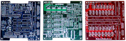
The "expansion board" is actually a set of three boards that work together.
Most people will need just two of the three boards to build a complete system: one main board and one power board. This combination provides all of the "input" functions (buttons, nudge, plunger, IR), plus 65 outputs for feedback devices. Each board is 10x10 cm (about 4"x4"). They're designed to stack vertically, one atop the other, with the KL25Z on top of the stack, so the whole setup has a very compact footprint. Each board requires power connections to your main PC power supply and to the secondary power supply that runs your feedback devices. Each board also requires a data connection to the next board, which can be conveniently handled with a small ribbon cable.
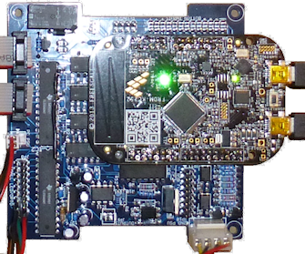
Main board: The main board is where the KL25Z attaches. The KL25Z sits on top of this board in a set of sockets, so there are no wires needed to connect it. You also don't need to plug anything into the KL25Z itself, other than the USB cable - all of the connectors for button inputs and device outputs are on the main board, grouped by function. If you've looked at the old v1 Build Guide for the standalone KL25Z vesion of the controller, where you have to connect things to scattered KL25Z pins, you can probably appreciate how much neater the connections are in this setup.
This board is designed to go at the top of stack, since you need some headroom for the KL25Z.
Part of the purpose of the main board is to break out the connections for various KL25Z inputs into separate headers, grouped by function:
In addition, the main board provides several special functions of its own that go beyond what the basic KL25Z setup can do:
"TV ON" relay. This is a mechanical relay that pulses on once, briefly, after a programmable delay from system power-up. You can attach wires from the relay to your TV's On button so that the relay pulse simulates pushing the On button during system start-up, turning on your TVs. The relay is a double-pole type, so two TVs can be controlled this way. This solves the problem that many virtual cab builders run into with TVs that don't turn on automatically when the power is restored. It saves you the trouble of turning on the TVs manually every time you turn on the system.
Note that the relay can't be used to switch the main AC power to the TVs. It's just a small "signal" relay that can only handle the low voltages in the TV's control circuits. To control the AC power, you need a smart power strip or a separate high-voltage relay. The TV ON relay's function is to simulate pressing the TV's ON button a short time after power comes on, for TVs that need this.
You can also turn on TVs via IR remote control. The board has connections for an IR LED and an IR sensor, which lets Pinscape act as a learning, universal remote control. You can use the sensor to teach Pinscape the ON button code for your TV's remote control, and then Pinscape can transmit that code via the IR LED each time the system powers up. This lets Pinscape turn on your TVs wirelessly, eliminating the need to take apart the TVs or solder wires to their buttons. The software fully supports the IR features starting with the 23 March 2017 firmware update.
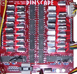
Power board: This board simply provides 32 feedback devices outputs, each with a high-current MOSFET driver and with full PWM control.
PWM means that each output has adjustable intensity. This translates to variable brightness for lamps and LEDs, variable speed for motors, and variable loudness for contactors and coils.
Each output can handle about 5 amps. This is enough that you can hook up just about any device in the virtual pin cab world directly, without any extra relays or amplifiers. 5A is enough for typical shaker motors, gear motors, fans, beacons, contactors, and even real flipper coils and knockers. The only thing the outputs can't handle is devices that run on AC power; for those you'd need a relay. (The 5A limit comes from the circuit board, by the way, not from the MOSFETs. The exact MOSFET type you select is up to you, but the typical ones will handle anywhere from 7 to 20 amps. The 5A limit is from the width of the traces on the PCB board and from the type of connector pins used.)
Note that the power board's 32 outputs are in addition to the main board's 16 flasher/strobe outputs, 16 flipper button light outputs, and knocker output. So we're up to 65 outputs when you combine the two boards. But if that's not enough, you can add a second power board for another 32 outputs. If that's not enough, you can add a third. In fact, there's no hard limit to the number of boards you can add, although in practice things might get iffy after three or four boards, because the data signal that connects the boards will eventually get too weak after traveling down too long a wire run. The firmware also has its own limitations, currently allowing for a maximum of 128 total outputs.
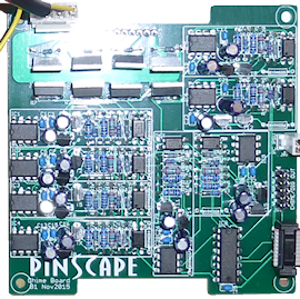
Chime board: This third board is optional. Most people won't need one. This board provides 8 timer-protected outputs. Each one is just like the knocker output on the main board: there's a hardware time limiter that prevents the output from staying on for more than about 2 seconds continuously.
These outputs are MOSFET-powered, exactly like the outputs on the power board, so you can hook up high-current devices directly. Unlike the power board outputs, these outputs are "digital" - they're simple on/off outputs without PWM intensity control.
The main board has the one dedicated knocker output because replay knockers are pretty common in virtual cabs. It has only the one timed output because that's as many as most cabs need, and the circuitry takes up a lot of space. But some virtual cabs do have multiple coil devices, thus this add-on.
As with the power board, the chime board can be doubled up or tripled up if you need more than 8 of these special outputs.
Even though it's called the "chime board", you could use it for other similar outputs that need the same timer protection. The board got this name because chimes seem to be the most common use case in virtual cabs (apart from replay knockers). But if you're using real pinball bumpers or slingshot assemblies, you might want to put them on chime board outputs as well, since they also have coils that aren't designed to be left on for long periods.
You can order everything directly from Mouser using the saved carts linked above, but you might save some money by shopping around for some of the parts.
DigiKey.com is a direct Mouser competitor that has a similarly comprehensive catalog. You won't find any big differences in pricing vs Mouser, but some components will be slightly cheaper at DigiKey and some slightly cheaper at Mouser.
Jameco is a more hobbyist-oriented supplier with a much smaller selection than Mouser and DigiKey, but often has better prices on what they do carry.
Tayda Electronics is another hobbyist-oriented supplier. They're based in Thailand, so shipping to the US might take longer than the domestic options, but their prices are often much lower.
Pololu is a good place to buy your connectors. They sell breakaway strips of pin headers in 1x40 and 2x40 sizes - you can buy a couple of these and break them into the various sizes needed for the boards. If you're building all three boards, you'll need one 1x40 and two 2x40 (you might need one more of each if you're doubling up on the power or chime board). The breakaway strips will save about half the total cost vs buying individual pre-cut pin headers. Pololu also has good prices on packs of the crimp housings, and on the crimp pins that you need to fill them. While you're there, you might pick up their wonderful crimp tool. It makes crimping incredibly easy and reliable. It's about $35, which is pricey for such a specialized tool, but it's a really good quality piece of equipment, and it's cheaper by far than any alternatives I've found (e.g., Mouser's options run upwards of $100).
For most of the components, you don't need to buy the exact same parts. For example, the resistors and capacitors are all generic; just get the same values. Do pay attention to the package sizes, though, since some variations are too big for the space allocated on the boards.
The most expensive parts are the MOSFETs and optocouplers. They're not really that expensive individually, but you need lots of them. You might be able to save a fair bit on these via eBay, especially if you're willing to wait for shipping from China. For the MOSFETs, there are a number of substitute parts that will work, so you can choose by price. At the moment, the cheapest version seems to be the FQP30N06L. Look for sellers offering them in lots of 10 or 20. Anything in the FQPxxN06L series should work equally well.
Note that the Mouser carts don't include the TLC5940NT chips. You'll need two of these for the main board plus two for each power board. (There are none on the chime board.) Mouser doesn't sell them because TI just stopped making them in the PDIP version (that's the chip package type with pins that stick through holes on the circuit board for soldering). TI only makes surface-mount ("SMD") versions now. I stuck with the PDIP version because they're easier for us hobbyists to solder than SMD chips, and for now they're still readily available on eBay. You should be able to get them for about $1 per chip. If they eventually become hard to find, I'll revise the circuit board to use the SMD version, but I'd rather hold off as long as possible to keep the soldering job simple.
Before settling on the modular design above, I was working on two alternative configurations. I'm not going to prototype or test or maintain these going forward, but I thought I'd mention them and make the files available here for anyone who wants to use one of them as a starting point for their own version.
The One Big Board design: The first alternative packed just about everything in the winning design into a single board, 10x16cm. This had a slightly different mix of output power circuits, owing to the slightly smaller overall surface area: 24 MOSFET outputs and 24 Darlington outputs. That would have been enough for most cabinets, but the two-board design had enough space to change the mix to 16 Darlingtons and 32 MOSFET outputs, which is preferable because the MOSFET outs are way more flexible (due to their greater power capacity) and cost about the same per output as the Darlingtons. The slightly smaller footprint of the winning design is also a mark in its favor, as is the lower cost of manufacturing the small boards. Many PCB makers have special hobbyist pricing for boards up to 10x10cm in size, which makes the pricing non-linear: it's cheaper to make two 10x10 boards than one 10x16.
Arduino shield style: The second configuration was another 10x10cm two-board setup, almost identical to the winner, but it had the added feature that the connectors between layers were optimized to allow use of the long-tailed socket headers that Arduino people use to connect stacks of "shield" boards. This had the appeal that it didn't require as many wires, but the trade-off was that it required a somewhat tricky bit of jumper wiring on the boards to make it modular. I didn't like the complexity that added.
The thing that made up my mind was a suggestion on the vpforum thread for adding more timer-protected outputs. That required adding a third board to the mix, which would have been difficult within the more rigid constraints created by the vertical connector tower. It was easier to add the chime board using cable connectors. It also made me realize that it would probably be easier to add other special expansion modules like this in the future, if other needs emerge.