An improved version of this material is available in the second edition of the Pinscape Build Guide, in the Cabinet Body chapter. See "Plunger and Launch button".
The new version in the Build Guide has slightly revised measurements, and is presented in a much easier-to-read format. And the full Cabinet Body chapter provides a lot more context than just the plunger cutout. It includes measurements for all of the other front-face features (the coin door cutout, buttons, leg bolts, and lockbar mounting), as well as advice on the vertical positioning of the plunger and its interaction with the TV placement.
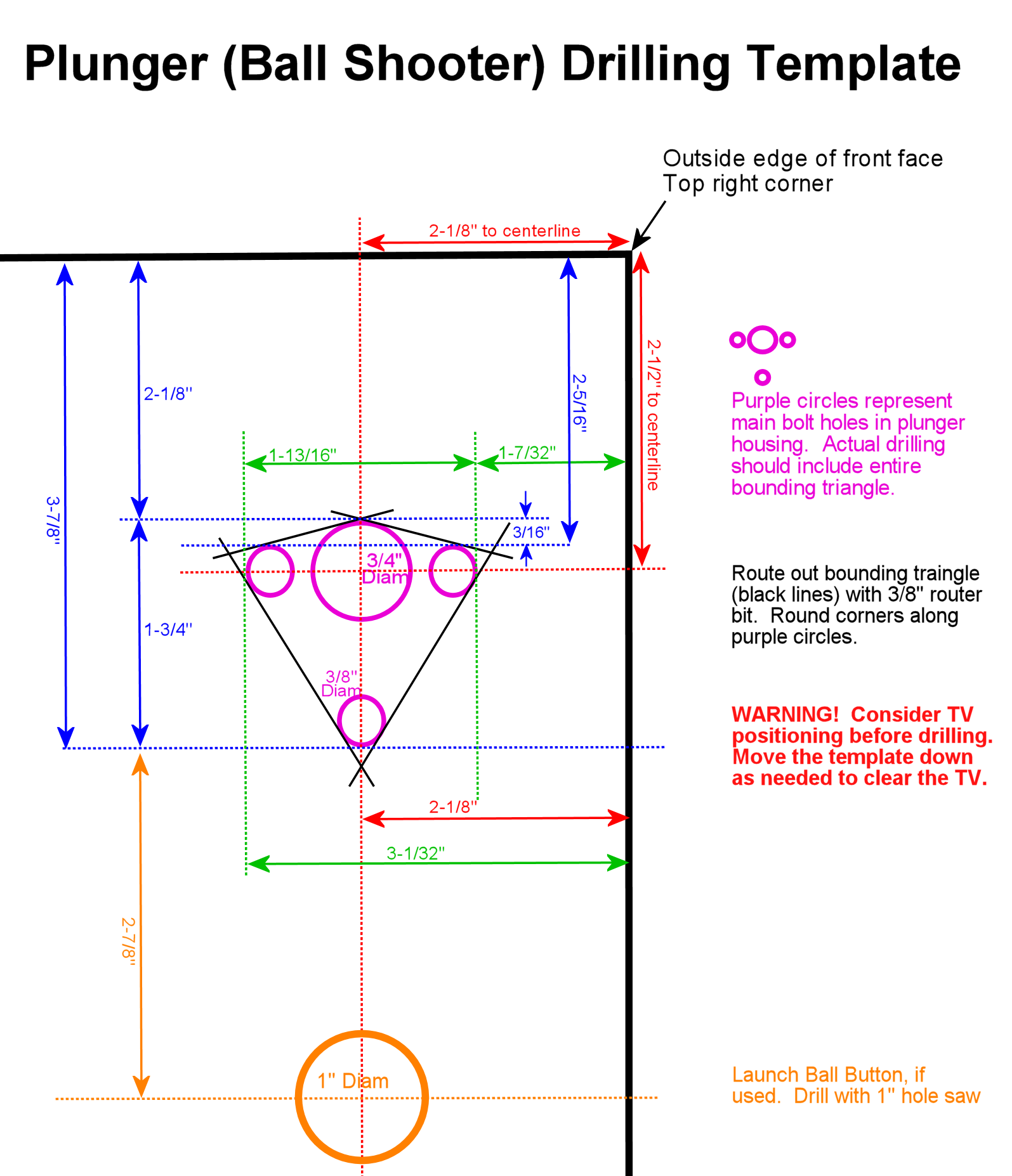
There are a number of plans floating around the interwebs for building a pinball cabinet. One of the little details that seems really hard to find is the drilling pattern and positioning for the plunger housing. I finally gave up looking and solved the problem by taking detailed measurements from a couple of real pinballs with standard plunger configurations. I came up with a template for the standard positioning used on most real pinballs. For virtual cabinet builders, I also included a hole for the Launch Ball button, which you can include or omit as desired.
A word of caution! The standard plunger location on a real pinball lines up with the playfield. This might create problems in a virtual cabinet, because the playfield TV sometimes overlaps with that area. Be sure to consider how you're going to position your TV before drilling for the plunger. If your playfield comes up to the very front of the cabinet, as some people prefer, there won't be any room for the plunger at the standard position. If this is the case on your build, you'll have to lower the plunger enough that it occupies open space below the TV. My preference is to use the standard plunger positioning and accommodate it by moving the playfield TV back about 3 inches from the front wall. I use a custom "apron" with instruction cards to fill the space. I like the resulting look - the plunger is in the right place, and I think the apron makes for a more physical, 3D appearance than filling the entire area with video. But opinions on this are sharply divided; some people just can't stand losing that first 3 inches. You'll have to consider which compromise is more agreeable to you.
The shape of the hole needed for the main housing is basically a triangle with rounded corners. (Yes, it actually has four sides, but the top is flat to a first approximation so I'm going to call it a triangle.) The easiest way to drill this is with a router, using a 3/8" bit to get rounded corners that match the diameters of the bolt sockets on the housing. If you don't have a router, you can drill 3/8" holes at the corners and cut between them with a jigsaw.
A couple of other little details - things that don't seem to be documented anywhere. The bolts needed for a standard Williams or Stern housing are #10-32 x 3/4". There's a special part called a "ball shooter mounting plate" that makes attaching the housing much easier. This goes on the inside and serves as the backing plate for the bolts. It's cheap (about $2) and practically essential, but as far I've seen, none of the commercial plunger kits for virtual pinball include one. Any pinball supplier will have it. Look for Williams part number 01-3535 or Stern/Sega/Data East reference 535-5027-00.
Finally, I'd like to point out that Pinball Life.com sells an amusing plunger accessory that seems perfect for people building custom cabinets. Look for their Knobless Shooter Rod. It's just a standard plunger rod without any knob/handle attached, so you can use your imagination (and perhaps a 3D printer) to create your own custom knob. That and a little epoxy will let you create a completely custom look for your plunger, befitting a hand-crafted virtual cab project.