This is a small printed circuit board design for connecting the TSL1410R optical sensor to the Pinscape expansion boards.
You can have this board fabricated at OSH Park for about $3.50. It's so cheap because it's so small - it's less than one square inch overall. OSH Park charges by the square inch, so it's a very good source for small boards like this. What's more, they make it really easy - you can simply upload the ".brd" (board layout) file to have it made.
Note that this design is for the TSL1410R sensor, but I'm pretty sure it'll also work with the TSL1412S version. I think both sensors have an identical pin layout. I haven't actually tested this claim, so please double-check everything if you're using the TSL1412S. (Also, please let me know how it works, so I can either remove this claim or remove the warning!)
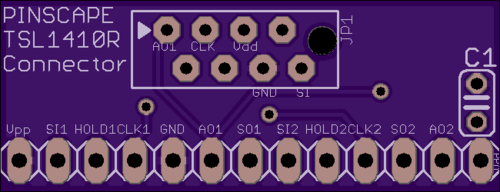
The 13 pin pads along the bottom of the board align with the pin pads on the sensor. The board provides all of the internal connections between different pins on the sensor, so you just have to solder the pin pads on the board to the pin pads on the sensor, and then run a ribbon cable (or five individual wires, if you prefer) from the header at the top (labeled JP1) to the expansion board.
JP1 is designed to connect to a ribbon cable via a PCB to ribbon cable connector. The wires on the jumper are arranged in the same order as the expansion board plunger header, so this makes it really easy to connect everything. Just use an 8-conductor ribbon cable and a standard IDC socket at the other end, and you'll have a neat little connector that you can simply plug into the expansion board header.
If you're using the stand-alone KL25Z rather than the expansion boards, you can still use this connector. In this case, you'll probably want to skip the ribbon cable and instead run individual wires to the five labeled pads on JP1 (AO1, CLK, Vdd, GND, SI). Connect these five wires to the corresponding KL25Z pins as described in the Build Guide.
Note that there's also a slot for a 0.1uF ceramic capacitor. This isn't strictly required, but the data sheet for the TSL1410R recommends it, since it helps reduce any electrical noise on the power connections to the sensor and thus lets the sensor provide a cleaner data signal to the microcontroller.
Full assembly instructions will be in the v2 Pinscape Build Guide, but here's a quick outline. You should attach the capacitor and the JP1 connector or wires first. Trim the wires sticking out of the bottom from those connections so that the bottom of the board is as flat as possible, since that's the side that faces the sensor. Now place the sensor and the board back-to-back with the pin pads aligned. Make sure the sensor's optical window is facing away from the board - you don't want the board to block the window! The pin pads should be aligned on the same edge (board and sensor) so that the board is roughly centered over the back of the sensor. Double-check that the pins are in the right order by cross-referencing with the TSL1410R data sheet. The pins are all visibly labeled on the board, so make sure the labels are aligned with the same pins according to the data sheet. Now you can solder the sensor and board pin pads together. The easiest way is probably to run a short length of stripped 24-gauge wire through each hole, soldering the outside end of each wire to the pin pad on the board and sensor.