This book is licensed under a
Creative Commons
Attribution-ShareAlike 4.0 International License. In brief, this means that
you're free to use, share, and adapt this work for any purpose,
without seeking further permission from the author, as long as you
give appropriate credit and pass along the same permissions in
your adapted material.
The Pinscape Controller firmware and the Expansion Board hardware
designs have similar Open Source license terms. See their respective
license files for details.
No Warranty
Just to be sure there's
no misunderstanding, I want to spell out that this documentation and
the related mechanical and electronic designs and computer software
have NO WARRANTY of any kind. This entire enterprise is a hobby
project, and I don't have a Quality Assurance department to
independently test any of it, so the material undoubtedly contains
numerous errors.
I'm making all of this available at no charge in the hope that it's
useful, but I can't guarantee that it'll work or that you'll be
successful building any of it. Work involving electronic
circuitry has the potential to damage other connected equipment,
including expensive items such as computer motherboards.
Proceed at your own risk.
THIS WORK IS PROVIDED "AS IS", WITHOUT WARRANTY OF ANY KIND,
EXPRESS OR IMPLIED, INCLUDING BUT NOT LIMITED TO THE WARRANTIES OF
MERCHANTABILITY, FITNESS FOR A PARTICULAR PURPOSE AND NONINFRINGEMENT.
IN NO EVENT SHALL THE AUTHOR BE LIABLE FOR ANY CLAIM, DAMAGES OR OTHER
LIABILITY, WHETHER IN AN ACTION OF CONTRACT, TORT OR OTHERWISE,
ARISING FROM, OUT OF OR IN CONNECTION WITH THE WORK OR THE
USE OR OTHER DEALINGS IN THE WORK.
Caution
Building a
virtual pinball machine involves some inherently dangerous equipment
and activities, such as power tools and high voltages. Read the
manufacturer's instruction manuals for your tools and follow their
safety precautions. Wear safety glasses, hearing protection, and
other appropriate safety gear for every task. Don't attempt anything
that you don't understand or don't feel comfortable with.
Exercise extreme caution when working with electricity, especially
with high voltages. Higher voltages can cause electrocution, and even
low voltages can start fires and damage other equipment. Always
disconnect the power at its source before doing work on anything
electrical. Don't just switch it off - unplug it from the wall
outlet.
I first started thinking about building a virtual pinball machine at
least a couple of years before I actually did anything about it. I
was on the fence for so long because I thought it was one of those
ideas that sounds better than it really is. I also thought I might
get bored of it quickly. I loved the idea of a life-sized
pinball simulator, but I didn't think the real thing could live up to
my mental image of it. It didn't help that Visual Pinball always
seemed a little disappointing on my desktop PC. I thought a cabinet
would just make the video game's limitations more obvious by putting it on a bigger
screen. You've probably heard it said that the great thing about a
virtual cab is that it's like having 1,000 pinball machines
packed into the space of just one, but surely the variety is only
of secondary importance: if it weren't fun to play one virtual table,
why would you want 1,000 of them?
But I kept coming back to the idea. I'd check in on the forums from
time to time to see what was new. At some point, people started
talking about putting "feedback toys" in their cabs1.
That's when I finally decided I had to build one. "Toys" are physical
devices that create special effects in sync with the on-screen action.
The thing that grabbed my attention most was the idea of using
solenoids for a tactile thunk when a flipper or bumper fires.
The ability to feel the game action struck me as a whole new
dimension that you can't get in mere video pinball.
It's probably needless to say that all of my early reservations were
turned around once I started building my cab.
If you're reading this guide, you're probably at least curious about
building your own cab. In case you're still undecided, like I was,
let me offer this nudge: I think a cab really is a different
experience from playing pinball simulations on a desktop PC. It's not
just the same thing in a different box. The real controls and the
full-scale physical setup are more than just decorations; they're
transformative.
I should temper that by adding that a virtual cab won't trick you into
thinking you're playing a real pinball machine. It's not that
realistic. But it's not just desktop video pinball in a fancy box,
either. "Virtual" and "real" pinball each have their own advantages,
and they're each fun to play in their own way. I'm fortunate to have
a small collection of real pinball machines at home, and while I'd never
consider the virtual cab to be a replacement for any of those,
it is a great addition to the lineup, adding its own unique play style.
Pin cabs aren't just fun to play; they're fun to build. They make
great DIY projects. As much as I enjoy playing games on my cab, I
also really enjoyed building it, and I'm still coming up with ways to
improve it. Most of that work is on the software side these days,
although I still tinker with the hardware, too. One of the great
things about this hobby is that most of the software involved is open
source, so if there's something you don't like, you can change it.
That's one of my motivations for sharing the Pinscape Controller
project: I wanted to bring the benefits of open source to the hardware
side. When I started my cab, most of the hardware options were
proprietary devices designed more with video arcade projects in
mind, so I'm glad that I've been able to add some more
pinball-oriented designs into the mix.
This is a great time to be building a DIY pin cab, thanks to a
confluence of trends. One is that real pinball continues to thrive
among collectors, which is good for us because it keeps an active
market going for the specialized pinball-machine parts we need for our
projects. Another helpful trend is the popularity of hobby robotics,
which has made lots of advanced electronics accessible to DIYers. A
third is the growing interest in virtual pinball itself, which has
attracted a talented group of people who work on the open-source
software that makes virtual cabs possible. Virtual cabs will keep
getting better as long as people are actively working on the software.
The Pinscape Controller
This guide has grown into a pretty comprehensive set of instructions
for building a pin cab, from the woodworking and trim hardware to the
electronics and the software. It started out with a much smaller
scope, of serving as the user manual for my Pinscape Controller
project, and that remains a significant part of the book. The
Pinscape Controller is an open-source hardware and software project
that can act as the central hub for connecting most of the specialized
input and output electronics unique to virtual pin cabs: buttons,
sensors, and feedback devices like solenoids and lights. The
controller can handle nearly all of the special I/O functions in
a pin cab, including:
Connecting flipper buttons and other pinball-style buttons to the PC
and using them to control the game
Connecting a physical pinball plunger to the software, via a
position sensor that detects its position and motion, so that you can
launch the ball the traditional way, with precise control for tricky
skill shots
Using an accelerometer to sense the motion of the cabinet,
so that you can nudge the cabinet and get a realistic, proportional
response in the simulated game
Connecting feedback devices to the PC, so that the pinball software
can create lighting effects and tactile effects cued to the game action
Physically, the core of the Pinscape project is the Freescale
FRDM-KL25Z, a tiny, self-contained computing device about the size of
a credit card. It costs about $15 and comes fully assembled and ready to
use. You don't need to know anything about electronics to set it up;
you just plug in a USB cable and load some software.
The KL25Z by itself does a lot of the heavy lifting. It has a
built-in accelerometer (a good one), which nicely handles nudge sensing.
You can connect buttons (like the flipper buttons) directly
to the KL25Z, with no more work than running some wires.
Beyond buttons and nudging, the electronics work gets a little more
complicated. If you want to hook up a plunger sensor or connect
feedback devices (lights, motors, solenoids), you have to buy some
electronic components, and do some additional wiring and electronic
assembly work. That's all laid out in detail in this guide, and it's
very scalable - you can do as much or as little of this as you want,
according to your interests and comfort level working with
electronics. And you can add new features over time; it's all pretty
modular. I've tried to make all of the projects approachable even if
you don't already know much about electronics.
For the plunger, several options of varying difficulty are available.
The easiest option only requires buying a particular kind of
potentiometer (about $6) and connecting three wires. A more complex
but more precise option is what I'd call an "intermediate level" DIY
electronics project. All options are documented in detail in this
guide with step-by-step instructions.
If you want to connect feedback devices to the KL25Z, that also
requires some additional electronics work. There are some simple
options involving pre-built circuit boards that you can buy on eBay or
Amazon. The more advanced and more full-featured options involve the
"Expansion Boards", a set of circuit board plans that you can build
yourself. Again, this is all documented in this guide.
The Pinscape Controller is an entirely "open source" project, meaning
that all of the software is free to use, all of the source code and
hardware designs are published, and you're free to change and
customize them in any way. I'm always happy to integrate any
customizations that are generally useful back into the official
version so that everyone can benefit from them, but you're also free
to make private changes for your own use if you prefer.
Cabinet build guide
Beyond the Pinscape-specific material, this guide includes a lot of
information about building virtual pin cabs in general. The goal is
to provide a complete instruction manual for the DIY pin cab builder.
The guide even includes information on the various commercial products
that can fill the same roles as the Pinscape project, for people who
aren't interested in DIY for those aspects and prefer something
that comes ready-made.
I'm including the general virtual cab building material because I
would have really liked something like this when I started on my own
cabinet. There's a lot of information on building these machines on
the Web, mostly in forums and blogs, but it's really scattered and
hard to find and navigate. There is one other full build guide out
there that I'm aware of, though: Major Frenchy's
Mame in a Box, which offers a
big library of video tutorials on pin cab building. If your learning
style favors video presentations, or you just want another resource to
add to this one, check it out.
I can't quite boil things down to a ready-made kit with a master parts
list and easy assembly instructions. There are too many possibilities
and variations for that. Every cab is unique, which is exactly as it
should be for a DIY enterprise like this. So I'll try to go into as
much detail as I can, but in many areas the information is more like
advice than outright instructions.
Currency and updates
The first complete edition of this guide appeared in October, 2019
(after about three years of partial versions that were kept online as
a work-in-progress). "Complete", in the sense of covering all of the
topics I set out to cover at a level of detail that I set out to reach
- but not necessarily "finished", in the sense of the last possible
word being said on every subject, the text set in stone, never to
change again. I still see it as an ongoing project, and I revise and
expand it from time to time as I encounter errors and omissions, and
to keep up with changes in the virtual pinball world. (Most recently
in October 2025, according to the electronic
librarian that keeps track of the text.)
Many parts of this guide have an inherently long shelf life, because
the "real" pinball machines that virtual cabs are based on tend to
look and act much the same year after year. I don't think that's
likely to change, either, because at least a part of pinball's market
demand comes from nostalgia. The pinball makers are aware of this and
know that they can't change things too much before people stop
thinking of their products as "pinball". A lot of the basic design of
a commercial pinball machine (and thus of a virtual cab) is pretty
well anchored in the 1990s. That's good for the longevity of this
guide, because it means the parts about cab building don't need to be
updated every couple of months to chase a new fad. The same is true
of the backgrounder sections on woodworking, soldering, and so forth.
Some things do change rapidly, though, some so quickly that I know
there's no hope of keeping any guide up-to-date with them. The things
that move at warp speed are primarily related to the core electronics
- specifically, the TVs and video displays and the PC hardware specs.
All of that tends to undergo a complete revolution every four to six
months. I know there's no hope of keeping a list of "Best Intel Chips
of 2026" or "The Sharpest TVs Right Now" up to date, so I
don't even try to provide such ephemeral shopping lists. Instead, the
relevant sections provide a more general, and hopefully more lasting,
idea of what to prioritize when shopping. My hope is that this will help
the material remain relevant and useful for at least a little while.
In between those extremes - the Moore's-law churn of consumer
electronics on the one hand, and the timeless arts of woodworking and
soldering on the other - there's another area that changes at a
middling pace: the special software and hardware devices for playing
virtual pinball. Visual Pinball, PinMAME, DOF, etc - these are
generally open-source projects, or in some cases tiny one-person
businesses, that are in active development and that come out with new
versions once in an unpredictable while. I confess that I don't track
every one of those projects closely enough to know immediately when
something I've written about it here needs to be updated, and even if
I did, it would still take me a while to catch everything up. So it's
best to treat the guide as a secondary source of information
for the big software components, and look to the projects themselves, or
forum activity from their contributors, for the latest news.
If you encounter any errors, or anything that's out of date, I'd be
happy if you pointed it out so I could try to fix it. You can contact me on
vpforums.org (my user ID there is mjr.)
An explanation of "section incomplete" warnings
I originally started posting this guide in draft form in October 2016,
when it was just a skeletal outline. Back then, most of the sections
were just placeholders, like this:
This section is incomplete and will be expanded when time permits. Material to be added: (Some notes about what I intended to write would go here)
Those placeholders were there so that I could use the guide as its own
outline, and also so that readers would know that I hadn't forgotten
about the topic in question.
I finally finished filling in all of the planned material in October
2019, so at that point there were exactly zero of those boxes
remaining. You probably won't see any in the current guide - but I
can't rule that out entirely. I'm still revising and updating the guide
on a regular basis, and occasionally a new topic comes up that's big
enough that it will take some time to cover. When that happens, I
might resort to adding a few of those boxes back in. If you see any,
they mean that there's some new material I intend to add when I get a
chance.
1In the vernacular of the Web forums, a virtual pinball
machine is called a pin cab, short for
"pinball cabinet", and most often shortened further still
to simply cab. If you're new to the forums, the
name might seem weirdly generic. But it makes sense in the context
of the forums, because the "cab" groups are only a small part of a broader
community that's interested in computer pinball simulation in general.
Everyone in the broader community plays computer-simulated pinball,
but mostly using ordinary desktop PCs or video game consoles. The thing
that distinguishes the "cab" crowd is that we embed our pinball PCs
in these elaborate housings based on the real machines.
2. What is a pin cab?
I'm not sure who created the first virtual pinball cabinet, but the
seed of the idea is pretty obvious in hindsight. Someone must have
been playing around with a pinball program on their desktop PC, and
wondered what it would be like to turn the monitor sideways, to make
the layout more like a real pinball table's proportions.
Then they thought to lay it down flat, so they could stand over it
like a real pinball playfield. And then what about switching to a big
flat-panel TV that's the same overall size as a real pinball table?
The finishing touch was putting the big TV inside an old cabinet
salvaged from a defunct real pinball, right where the playfield used
to go, for the full life-sized experience.
At its most basic, that pretty much sums up a virtual pin cab. You
take a Windows PC, install Visual Pinball and/or other pinball
simulator software, attach a TV in the 40" range as the primary
monitor, and put the TV inside a pinball cabinet body where the
playfield would normally go. Put another TV in the backbox to display
the backglass artwork. Connect some speakers in the backbox to the PC
sound card, and you have the full audio/visual simulation.
What makes this so special?
Okay, you're thinking, so a pin cab is just a desktop pinball player
in the guise of a real machine. Maybe that sounds somewhat
interesting: the idea of playing on a full-size
playfield is pretty novel if you're used to playing pinball in a
cramped little perspective window on a PC monitor. But in the end,
isn't it just the same game on a bigger screen? Wouldn't the novelty
wear off pretty quickly?
As they say in the infomercials, "but wait, there's more..."
Real flipper buttons! Once we have the displays in a proper
cabinet arrangement, we can't just plop a boring old PC keyboard on
top and go on batting the ball with the Shift keys like on the
desktop. It's a real pin cab, so it needs real flipper buttons.
Yes, you can connect the real buttons to the PC. There's a special
device called a key encoder that lets you do this. Key encoders are
fairly cheap and easy to set up (and the Pinscape Controller can
handle this function, of course). They trick Windows into thinking
you're still just pressing regular keyboard keys, so you can go on
using the same pinball software.
This makes a positively huge difference in playability. If you've
played any desktop pinball or tablet pinball, you probably already
have a sense for how awkward the controls are; you've undoubtedly lost
a good number of balls from having your fingers stray just a little
off the keys at crucial moments. Even so, it'll probably still be a
revelation the first time you play virtual pinball with real flipper
buttons.
You don't have to (and shouldn't) stop at flipper buttons, by the way.
You can hook up all of the standard buttons - the Start button, Magna
Save buttons, the coin chutes, even the service buttons inside the
coin door that let you access the operator menus.
A real plunger! Desktop pinball games all use a "timed" plunger
that pulls back as long as you're pressing a key. Which obviously
doesn't even remotely resemble how you interact with the plunger on a real
machine. On a cabinet, you can install an actual pinball plunger, and
connect it to a sensor that lets the PC read its position. This lets
you launch a ball exactly like in a real game. The Pinscape
Controller offers this capability, and several commercial options are
available as well.
Real nudging! Real pinball games are physical, mechanical
systems. The game action obeys the laws of physics, not the whims of
a video game programmer. I think that's why pinball remains
interesting to so many people even in an age of impossibly
sophisticated video games. Pinball's physicality means you can
interact with the game in a very direct and visceral way.
Desktop pinball offers an imitation of nudging that's half-hearted at
best, letting you "nudge" by pressing a button. Like the timed
plunger, it's nice that they tried, but it's nothing like the real
thing.
A pin cab makes it possible to bring back real physical interaction.
A virtual cab already has the same heft and feel of a real cab, so
you'll find yourself unconsciously nudging it like the real thing,
your brain expecting it to influence the ball. But what if you really
could influence the ball that way? Good news: you can! There's a
device called an accelerometer that can measure exactly the sort of
motion you impart to the cabinet by nudging. Accelerometers are cheap
and ubiquitous these days, thanks to smart phones. The
microcontroller board used in the Pinscape Controller has an
accelerometer built in, and the Pinscape software is set up to read
the acceleration data and send it to the pinball simulator
program. Most of the available commercial plunger kits offer the same
capability. The accelerometer doesn't just sense the fact that you
nudged, but actually measures the amount of force you applied, and
passes that along to the simulator, so that the response in the
simulation is proportional to the strength of the physical nudge.
Mechanical feedback! Blinking lights! Once the early cabinet
builders mastered all of the above, they started coming up with ways
to make the experience even more realistic by adding mechanical
feedback - devices that actually move inside the cab to simulate
flippers, slingshots, and bumpers.
Real pinball is a tactile
experience. The solenoids that whack the ball around are really
powerful, and you can feel them shake the cabinet every time they
fire. Digitized sound effects just aren't the same. For a more
realistic virtual experience, you can put solenoids and other
physical devices inside your cab that produce similar tactile
effects in the virtual game. The pinball software can
trigger these feedback devices in sync with the game play. So when a
bumper fires in the simulation, you can actually feel a solenoid fire
in your cab. You can likewise add bright LEDs and strobes that
flash in sync with game events. This makes for a dramatic light
show, much more interesting than just images on a TV.
The current generation of pinball software makes it fairly
straightforward to attach an array of mechanical devices and external
lights. You need another I/O controller for this capability, known in
this case as an "output controller". The Pinscape Controller can
handle this task, and there are several commercial options as well.
As for the feedback effects, there's a fairly standard set of lights,
solenoids, and motors that most people use, but the control systems
are so flexible that you hook up almost anything you can think of.
That sounds like a lot of work...
If you're new to the virtual cabinet world and you weren't already
acquainted with all of these bells (literally) and whistles, you might
be feeling a little intimidated by all of this. You might have been
picturing just the basics of the Windows PC in the fancy wooden box,
and you might have been thinking in terms of what you could build out
of ordinary PC equipment. But a lot of the stuff I just mentioned
obviously can't be done with ordinary PC parts alone.
That's where the Pinscape Controller comes in. The controller serves
as an interface between the Windows PC and the mechanical environment
of the pin cab - buttons, plunger, lights, mechanical feedback, and
acceleration sensing. We'll explain how to build the controller and
how to set up all of its functions.
When I first started building my own pin cab, I found it hard to get a
handle on all of the pieces involved. I knew I wanted real flipper
buttons, but how do you connect them to the PC? I wanted a plunger,
but how the heck do you make a PC take input from a plunger? I wanted
feedback devices to simulate the flipper solenoids and replay knocker
and so on, and I understood that I needed an LedWiz for that, but
beyond that I didn't really know what it could do or how to
connect anything to it. And knowing how many questions I had,
I shuddered to think about the questions I didn't even know enough
to ask.
The diagram below will, I hope, clear up some of that fog, especially
the unknown unknowns. It's is a comprehensive map of all of the
electronic systems and devices that make up a virtual pinball machine.
It doesn't answer the detailed questions, like exactly how you hook up
the LedWiz or install software, but it offers a bird's-eye view of
everything that goes into one of these machines. It shows what each
component does and how everything fits together. The idea is to let
you see the whole system at a glance. This diagram shows pretty much
everything electronic in a pin cab, so you should be able to
quickly spot any major components that weren't already on your radar,
and decide if you need to add them to your plans.
This is a big-picture view, but it's also loaded with details that
you can view interactively. Roll over any component with the mouse
(or tap it) to learn more about it. There are also some general notes
following the diagram. But don't feel like you have to cram for
a quiz: we'll cover everything in the chart in much
greater depth in later sections.
Roll over/tap features to show details • See notes below
Feature Details
Notes
The machine shown here is fully decked out. A bit more than fully,
in fact: some things are redundant, such having both a "real DMD" and
a "DMD TV". If you're in the planning stages for building a cab, you'll
only need to consider the components related to the features you
plan to include.
This isn't a complete wiring diagram or schematic. For that,
refer to the Build Guide sections on the individual subsystems.
"DOF" (referred to several times in the detail popups) stands for
DirectOutput Framework, one of the key pieces of software you'll want
to install on the PC inside a cab. DOF is the software that handles
the feedback devices.
How the Pinscape Controller fits in
You won't find any one box on the diagram that represents the Pinscape
Controller. That's because Pinscape is only one of several possible
choices for the functions it performs, and because Pinscape can perform
several different functions. So the diagram instead shows boxes for the
individual functions conceptually. If you do decide to use a Pinscape
Controller, it can fill any or all of these roles:
Key encoder
Accelerometer
Plunger interface
Output controller
Even though these functions are shown as separate boxes on the diagram,
a single Pinscape unit can fill all
of these roles simultaneously.
The Pinscape Expansion Boards also serve as the "Power
Booster", which is shown as another separate box.
If you're using the stand-alone KL25Z without
the expansion boards, you'll need something to serve as
the power booster if you want to connect feedback devices. The Build
Guide includes circuit plans.
15,11-337,235 24V power supply
#num top: 40%;
A number of common feedback devices require 24V DC power. These
include the most common type of contactors used to simulate
flippers, slingshots, and bumpers, as well as real pinball
chime coils. If you're using any devices requiring 24V, it's
handy to have a dedicated 24V supply in the cabinet, since this
isn't one of the voltages you can get from the secondary PC power
supply. If you don't have any of the common 24V devices, there's
no need for this extra unit.
390,19-823,236 Secondary PC power supply
#num top: 40%;
This is a second PC-type power supply that isn't connect
to your PC at all, but is used to provide power to the feedback
devices and other devices in your cab. You actually don't need
to use a PC power supply per se here, since we're not using any
of its special PC capabilities but just using it as a source of
5V and 12V DC. But PC power supplies are great for this because
they're an extremely cheap way to get a good high-current source
of 5V and 12V power. The reason we care about having a 5V and 12V
supply is that these two voltage levels are exactly what's needed
for most of the common feedback devices. And for devices requiring
other voltage levels, we can usually use inexpensive step-up
and step-down converters that draw their power from the 5V or
12V lines.
9,426-229,571 RGB flashers
Real pinballs usually have a number of "flasher" lights (bright lamps
under plastic domes) around the playfield. These produce a brilliant
light that's a key part of the show. Emulated tables will of course
include the playfield flashers in the on-screen image, but a video
monitor can't approach the brightness of the real thing. For a better
simulation of the original light show, virtual cabs often include
real flashers, usually a set of 5 positioned inside the cabinet
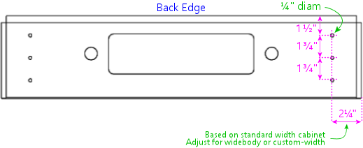
just behind the back edge of the playfield TV, and/or on top of the backbox.
The flashers in virtual cabs usually use clear plastic domes rather than
colored domes, and use RGB LEDs as the lamps, so the software can
use them to display flashes in any color. High-power
RGB LEDs that produce very bright light can be found on eBay: look for
"3W star RGB LED".
Note that this type of LED usually requires a resistor for each
color channel, to limit the electric current that flows through the
LED element. The resistors aren't shown on the diagram, but the
Build Guide section on wiring these devices has full details.
9,593-228,718 Strobe lights
This is another popular lighting effect on virtual cabs. These are simply
bright white lights. You can find the type most pin cab people use by
searching eBay for "22 LED strobe". These are designed
for use on cars and trucks, which means they run on 12VDC, which is
perfect for a pin cab.
9,744-206,913 Contactors/solenoids
The most basic "tactile" effect in a virtual cab is the thunk
made by the flippers, slingshots, knockers, and the like. The best way to
implement this is with something physically similar that actually goes
thunk itself. Digitized sound from the speakers just doesn't have
the same tonal quality or create the same sensation in your fingertips.
One obvious approach is to use real pinball flipper and bumper
assemblies, hidden inside the cab. Some cab builders do go that route, but
these are expensive and take up a lot of space. A good compromise that many
cab builders use is some kind of self-contained solenoid device. The most
popular choice is the Siemens 3RH1140-1BB40 24VDC contactor, which is basically
a beefy relay designed to switch high-power loads; it has a solenoid-driven
switching mechanism inside that makes a decently pinball-like sound. Another
popular option is automotive starter solenoids. Open-frame relays (easily
found on eBay) can also serve.
44,913-180,1100 Replay knocker
The replay knocker is such a distinctive feature of pinball machines that
most virtual cab builders wouldn't dream of being without one. Digitized
audio simply can't do justice to the hammer blast of a real knocker. Most
cab builders opt for an authentic knocker coil assembly, which you can buy
new from any pinball supplier. The real ones aren't very expensive, so hardly
anyone bothers to look for a DIY alternative.
9,1105-216,1246 Shaker motor
If you've ever played a real Earthshaker, or almost any recent
Stern game, you've probably encountered a shaker motor in a real pinball.
Shakers do what the name implies: they shake the machine (and the floor around it)
like a minor earthquake is going on. This is one of the most dramatic feedback
effects you can include in your machine, and it can really add excitement
during play. The implementation is simple: it's just a DC motor with an off-balance
weight attached. It's fairly straightforward and inexpensive to build one
yourself. If you do include one, you'll get a lot of use out of it, because
the standard DOF setup triggers it at well-chosen events in many tables,
even those without shakers originally.
9,1246-195,1398 Gear motor
Lots of real tables have something on the playfield that's controlled
by a little electric motor, which you can hear when it's in action.
These motors are usually linked with gears to the playfield features
they control, and the gears are what make most of the noise. For a more
realistic rendition of this distinctive sound, many cab builders like to
include an actual geared motor in their cab. The software can activate
this in sync with the game action, just like in the real game.
Two main types of motor are popular among cab builders for this role.
The first is the robotics motors available from many sellers on eBay:
small DC motors with a couple of brass gears attached.
They make about the right amount of noise, but some people think
the quality of the noise is too "whiny". The other common type is
auto windshield wiper motors. These are usually quieter and lower
pitched than the robotics motors.
9,1399-194,1564 Fan
A small handful of real pinballs featured fans on the backbox, most notably
Whirlwind. Given the puny number of real machines with fans,
you might wonder why you'd want one for a virtual cab.
But then you'd be surprised at how many virtual cab builders include one.
Like the shaker motor, the standard DOF setup triggers the fan on suitable
events in lots of tables that didn't have one in real life, so you'll get a
lot more use out of it than just playing Whirlwind and Twister.
And like the shaker, it's
a particularly tactile and dramatic effect that can be a lot of fun.
Many cab builders use fans that are designed for automotive or boat use
(since these conveniently run on 12VDC) and mount them on top of the
backbox a la Whirlwind. Some cab builders have created sneaky
hidden fan setups, with the fan inside the cab, blowing air at the player
through an opening in the coin door or a vent under the machine. My own
machine uses a replica of the Whirlwind fan with a custom
enclosure designed to fit the theming of my cabinet art.
29,1599-189,1764 Beacons
This is another popular light-show effect: a police-car rotating beacon
light, or a pair of them, on top of the backbox. A surprising number of
real machines had beacons; police themes are apparently as popular
in pinball as on CBS. (In fact, F-14 Tomcat had three,
and it wasn't even police-themed.) Like the shaker and fan, you'll get
plenty of use out of beacons even in games that never had them originally.
It's fairly easy to find suitably sized rotating lights of this sort
on-line, especially from auto supply stores. A bonus is that anything
designed for cars will conveniently run on 12VDC. There are also novelty
beacon lights designed as party decorations, but those tend to be
poor imitations.
3,1780-268,1986 Chimes & bells
If you're a fan of classic electromechanical pinballs, you might
consider installing some real chimes and/or bells. As with the knocker,
recorded audio doesn't do justice to real percussion instruments.
One option is to install an original pinball "chime unit" from the 1960s
or 70s. These are basically little xylophones, with three or four metal
bars and solenoid-driven hammers. The pinball manufacturers haven't made
these in a long time, so if you want the real equipment from the EM era,
your best bet is to find a salvaged unit on eBay. It might take some
patience since there aren't all that many in circulation. There's also
at least one modern reproduction unit available commercially (look for
"McCullough's Chime Unit"), but reviews are mixed as to whether it
sounds like the originals. The pinball suppliers don't sell full chime
units, but they do sell many of the parts, so you might be
able to cobble one together with a mix of original and improvised parts.
Another option is to find some suitable "shell" type bells, which were
used instead of chimes on many EM machines. You can use a regular knocker
coil to strike them. Bells have their own distinctive sound, so
a serious EM enthusiast might even want both bells and chimes, for more
variety and authenticity in configuring different tables. Yet another
possibility is an alarm-clock type of bell that strikes repeatedly when
energized, since a few real pinballs had these (Taxi, Space
Shuttle). Finally, a working decorative bell can also make a nice
"topper" (something mounted on top of the backbox), as in the original
Fire!.
4,2004-263,2049 LED strips/undercab lighting
Many cab builders like to put RGB LED strips on the bottom of the cabinet
or the back of the backbox. Look for "5050 LED strip" on eBay; these
are adhesive-backed strips with LEDs spaced every couple of centimeters,
designed for accent lighting. These strips only show one color at a
time across the whole strip (unlike the "addressable" strips, which
can show animated effects but require a special controller), so
they're best for ambient lighting effects. This is a popular "mod"
among real pinball owners, too. It creates a pool of light around
the machine, adding to the overall show.
423,823-731,1050 Step-up converter for knocker
#num top: 30%;
Real pinball knockers in modern games are mostly designed to run on 50V.
They'll work on lower voltages, but to get the proper amount of force for
the knocker effect, you need at least 35V or so. There's nothing else in
a typical virtual cab that needs that kind of voltage, so in all likelihood
you'll end up needing a special power supply just for the knocker. A cheap
and easy way to do this is to use a step-up voltage converter. These are
available on eBay for about $15. These take 12V as input (which you can
get from your secondary PC power supply), and let you dial in a higher
voltage for the output up to some limit. Look for a converter that can go
up to at least 35V, and preferably closer to 50V, and one that can supply
about 5A at the highest output voltage.
430,1058-749,1209 Step-down converter for shaker motor
#num top: 35%;
If you build a custom shaker motor, you'll probably want to base it on
a 12V DC motor, which means that you could power it directly from the 12V
line from your secondary power supply. However, many people find that
their shakers are too intense at full power, so they want to be able to
turn down the power a bit. One easy way to do this is by dropping the
voltage slightly with an adjustable step-down voltage converter. You
can find these on eBay for a few dollars. These take 12V as input and
produce an output voltage that you can adjust to any lower voltage.
Connect the output to the motor, and adjust the output (by turning
the control screw on the converter) to get the level of intensity you
find most pleasing.
419,1271-719,1403 Output controller
#num top: 20%;
To control feedback devices, you need an output controller. This is
a special device that you connect to the computer with a USB cable.
The device takes software commands from the PC and translates them to
electrical signals that turn your output devices on and off, in sync
with the on-screen game action, to create feedback effects to enhance
play. Almost any sort of electrical device can be used for feedback:
lights, motors, solenoids, bells, chimes. Some controllers use relays
to switch connected devices on and off (e.g., Sainsmart relay boards).
Others use solid-state (transistor) circuitry (LedWiz, PacLed, Pinscape).
Solid-state controllers almost always require some sort of "power booster"
to connect anything more powerful than an LED or small lamp.
$pinscapeLogo$The Pinscape Controller can serve as an output controller. If you use
the stand-alone KL25Z, the number of outputs is limited: about 20 devices
if you're also using it for any button inputs, or about 30 if not. The
plain KL25Z also requires power booster circuits to power anything, even
small LEDs. With the expansion boards, the number of outputs is practically
unlimited, plus the power boosters are built in, so you can connect
powerful devices like solenoids and motors directly.
419,1445-703,1643 Output power booster
If your output controller has solid-state (transistor) outputs, you'll
probably need some kind of power booster to connect anything beyond
LEDs and small lamps. The LedWiz and PacLed devices
both have this requirement, as does the stand-alone KL25Z with the Pinscape
software.
There are several ad hoc solutions that work with any controller.
One is to use relays; that's a simple solution, but has some drawbacks.
Another is to use the common "LED amplifiers" sold on eBay. These work
for high-current LEDs but might not be suitable for solenoids and motors.
For a more robust solution, you can use a booster designed specifically
for your controller. Zeb's Boards sells specially designed booster boards
for the LedWiz and PacLed devices. That's a more expensive option, but
easy to set up and superior to the ad hoc solutions.
$pinscapeLogo$If you're using the Pinscape Controller with the expansion boards, you
won't need any other boosters, because the expansion boards have powerful
booster circuits built in. If you're using the stand-alone KL25Z, you can
use one of the ad hoc solutions (relays, LED amplifiers), or you can build
your own inexpensive solid-state booster circuits using a simple circuit
design detailed in the Build Guide.
784,839-1056,1191 Addressable LED strips
#num top: 25%;
An addressable LED strip is an adhesive-backed strip about a
centimeter wide with a row of small LEDs down its length.
"Addressable" means that each LED on the strip can be controlled
independently, for animated lighting effects. This is still a
relatively new and rare "toy" in virtual pin cabs. Some cab
builders place these strips along each side of the playfield TV,
where the addressable lights can be tied to flashing lights and
other events on the playfield.
A special controller device is required to connect this type of
light strip to the PC, typically by USB. Free open-source firmware
is available that turns a Teensy 3.1 (an inexpensive Ardunio-type
USB device) into an addressable strip controller that works with
Visual Pinball.
735,1705-1003,1853 Plunger interface
#num left: auto; right: 0px; top: 15%;
This is a USB device that connects the plunger sensor to the PC.
Several options are available, including commercial products from
Zeb's Boards and VirtuaPin. Many of the available plunger devices
also include accelerometers for nudge sensing, and some also
include key encoders for button input. Plunger input is sent to
the PC as joystick input, since that's the format that Visual Pinball
and other emulators use to read the data.
$pinscapeLogo$This is one of the roles the Pinscape Controller can fill.
In fact, plunger sensing was the whole project's original purpose.
548,1746-735,1988 Plunger sensor
#num top: 25%;
To connect a standard pinball plunger to the PC, you need some kind
of sensor that reads the position of the physical plunger and
converts it into an electrical signal. There are many approaches.
The Pinscape Controller can use an optical sensor that
essentially takes rapid pictures of the plunger and finds the
position by scanning the images; it can also work with
a potentiometer that's mechanically linked to the plunger, using
the varying electrical resistance of the pot to determine the position.
The Zeb's Boards kit uses a quadrature sensor,
which senses the motion by counting pulses in a moving magnetic
bar code. The VirtuaPin kit uses an IR proximity sensor, which uses the
brightness of infrared light reflected from the tip of the
plunger to estimate the distance from sensor to tip.
The type of sensor you use will depend primarily on which
controller you choose; if you go with a commercial kit, it will
include the sensor.
Note that virtually all of the sensor options are designed
to work with a standard pinball plunger assembly. The
commercial kits usually include the plunger.
For Pinscape or other DIY options, you can get the
plunger assembly from any pinball parts supplier.
748,2018-973,2134 Accelerometer
#num top: 25%;
Nudging is such an integral and unconscious part of real pinball
play that good emulation demands a way to sense when you nudge,
shake, or shove the cabinet. The best way to do this is with
an accelerometer. A good one can tell the difference between
a slight nudge and a hard shove, allowing the simulation to
react proportionally.
Visual Pinball and other pinball emulators have good support
for accelerometer-based nudging. They take accelerometer
input via the standard USB joystick interface, so you just
need a device that reports acceleration data this way.
$pinscapeLogo$The Pinscape Controller can fill this role
(and the accelerometer on the KL25Z is very good). Most of the
commercial plunger kits also include a nudge feature, so you
probably won't need a separate accelerometer if you have any sort of
plunger device. If you decide not to install a plunger, you can
install a Pinscape Controller or one of the other plunger kits for
its accelerometer features alone if you wish.
960,15-1301,158 Switched power strip
This is a second power strip that provides line power to
all of the secondary devices in your system: the TVs, the
audio amplifiers, and the feedback devices. The line power
coming into this strip is controlled by the power switch
relay, so the strip receives power when the PC is turned
on and is effectively "unplugged" when the PC is off. This
provides nice integration for all of the systems in your
cabinet so that you can control everything with the main
PC soft power button.
An alternative to using the switching relay and a
second power strip here is to combine everything into one
"smart" power strip designed for computers. A smart strip
has a "master" outlet that plugs into the PC, and controls
the other outlets according to whether the PC is turned on
or off. This is simpler to set up than using a separate
relay, but some people have trouble getting these to work
reliably. Some motherboards don't seem to draw enough
power to trigger the "smart" switching function on some
of these strips.
1286,17-1526,247 Power switch relay
#num top: 50%;
This lets the PC control power to all of the secondary
systems in your cabinet: the TVs, the audio amplifiers,
and the feedback devices. This works as follows: when the
PC is turned on, the 12V power supply from the PC turns on,
which activates this relay, supplying power to the second
"switched" power strip. When the PC is off, the 12V line
turns off, which turns off the relay, which cuts power to
the second power strip. This effectively "unplugs" all of
the devices on the second power strip. You'll want to choose
a relay specifically designed for switching high-power loads.
The type designed for air conditioners and water heaters is
perfect. Because of the high voltage going through the
relay terminals, you'll want to be sure to thoroughly enclose
this relay in a protective plastic box so that you don't
ever accidentally touch any exposed wires, and so that
nothing shaking loose in the cabinet can ever come into
contact with the wires.
An alternative to the power switch relay is to use a
"smart" power strip designed for computer use. Smart power
strips do the same thing as the relay, but this action is
built in to the strip, so you don't have to buy extra parts
or do any wiring. Smart power strips are more expensive,
though, and some cab builders have had problems with their
sensitivity. Smart strips are triggered by the amount of
power being drawn through the "master" outlet connected to
the PC, so if your PC doesn't draw enough power, it might
not trigger the smart strip to turn on the other outlets.
An external relay doesn't have this
problem because it's triggered by PC power supply voltage
output rather than its current input, which makes the relay
approach work on every PC. Smart strips can also be
perfectly reliable, but this depends on the combination
of PC and smart strip model you choose.
1536,17-1774,161 Main power strip
#num top: 50%;
For the PC power supply connection, you'll want a simple
power strip that's left plugged in all the time. This lets
you control power to the PC with the "soft" power button.
Most people use a power strip with a built-in surge
suppressor to protect the PC from power spikes in your
house wiring and utility service. For a neat, integrated
look to your cabinet, mount this inside the cabinet, and
run its power cord out through a hole, to serve as the
main power cord that you plug into the wall outlet.
Note that most power strips have a built-in manual switch
to turn power to the outlets on and off. Even though
we're calling this the "unswitched" power strip, it's
perfectly okay to use a power strip with one of these
manual switches. You'll just ignore that switch and
leave it on all the time.
593,336-1045,571 Playfield audio amplifier
This is a secondary audio amplifier, connected to your
extra sound card. This is an optional system; most cab builders
don't bother with it. If you choose to use it, this is simply
another amplifier like the one powering your main speakers.
This one connects to the second sound card in the PC and to the
playfield effects speakers, usually positioned inside
the cabinet under the playfield TV. The purpose of this second
set of speakers is to audibly place the table sounds effects
closer to their simulated sources. The table sounds are things
like the ball rolling around and bumping into things, the flippers,
the bumpers, and so on - sounds that in the real game would
be coming from the playfield area.
One alternative to a separate playfield audio amp is to
use the speakers built in to your playfield TV. Many flat
panel speakers are too small and tinny for this to sound any
good, though. Another alternative is to use a multi-channel
amp for the main audio amplifier, with enough independent
channels to drive the main speakers and the playfield
speakers.
594,575-983,792 Playfield speakers
#num top: 50%;
This is an optional, secondary set of speakers dedicated
to reproducing the playfield sound effects, such as the ball
rolling around and bumping into things, the bumpers, the flippers,
etc. These speakers should be placed inside the main cabinet,
under the playfield. Visual Pinball doesn't currently do
anything to position these sound effects spatially, so a single
speaker is all you really need here. However, you'll probably
want a stereo pair anyway to help spread out the sound so
that it doesn't sound like it's all coming from a single point
on the playfield. You can also use a separate subwoofer for
this set of outputs. Some people use "tactile" subwoofers
here - the type that video gamers and home theater enthusiasts
attach to their chairs to create a Sensurround® effect.
A tactile subwoofer can let you feel the ball rolling and
bumping effects through the cabinet, which can add to the
realism, although you might find that you have to edit some
tables to tone down their effects. Some are too much of a
good thing with a tactile sub.
An alternative to using separate speakers here is to play
these effects through your playfield TV's built-in speakers.
Flat panel TV speakers are often too small and tinny for
this to sound any good, though; many table
effects need good bass reproduction to sound right.
1247,404-1705,556 Main audio amplifier
#num left: -4ex; top: 50%;
The audio amplifier for your main speakers. This connects to your
PC's audio output - the "line out" jack on your motherboard, if
it has one, or on your main sound card - with a standard audio
cable. Many types of amplifiers can be used here. Many people
use car amps, since they're compact and run on 12V, which means
they can be powered from a PC power supply. Another popular
option is to use powered computer speakers. You could even use a
home-audio receiver or amplifier, although these tend to be too
bulky to easily fit in a pin cab. If you use a subwoofer, you'll
want at least a "2.1" channel amp - two stereo channels plus a
mono subwoofer channel. Some 4-channel car amps can be wired
with one pair of channels "bridged" together to serve as the
subwoofer channel.
1211,580-1720,776 Main speakers and subwoofer
#num left: 25%; top: 5%;
If you're building your cab in the style of the real machines from
the 1980s and 90s, the main speakers will consist of a pair of small
(4" to 5") "satellite" style speakers mounted behind the speaker
panel in the backbox, and a separate large (8" to 10") subwoofer
mounted on the floor of the main cabinet, facing down through a
circular opening. Cab builders often use car speakers for these,
since many good options are available in the right size range.
If you're building your cab in the style of an older machine from
the electromechanical era, you'll have to be more creative about
where to put the speakers, since the "sound systems" on those
machines consisted of actual noisemakers (chimes and bells), not
speakers.
1440,821-1972,989 Backglass TV
This is a TV positioned where the translite or backglass would
normally go in a real pinball. This is connected to the PC video
card with HDMI or DVI like an ordinary PC monitor, and Windows sees
it as a second display. If you haven't done this before, it's
easier than it sounds, because Windows has built-in support for multiple
displays that actually works pretty effortlessly. Visual Pinball and other
emulators can easily be set up to display the animated backglass
graphics on this separate monitor for realistic play.
If you build your cab following the 1990s style, with a separate
speaker/DMD panel, most
30" widescreen (16:9) TVs will be a good fit. They're almost
exactly the right width, but they're not quite tall enough, so
there will be about a 1" gap above and below. You can cover
the gap with a painted or decal mask on the translite.
Some cab builders opt for a single
monitor filling the whole backbox area rather than using a
separate speaker panel. That arrangement is even tricker
because the backbox has a nearly square aspect ratio, and
square TVs simply don't exist. The usual solution is to use
a widescreen monitor in portrait mode, and submerge part of
into the cabinet below the backbox. This has disadvantages,
obviously.
1200,839-1378,874 Backglass TV video cable
The backglass TV connects to the PC video card with an ordinary
video cable, usually HDMI on the TV side, and either HDMI or DVI-D
on the PC side.
1482,1095-1951,1165 Real DMD
Most real pinballs from the 1990s and later used Dot Matrix Displays,
or DMDs, positioned in the speaker panel at the bottom of the backbox.
The real DMDs from the 90s were mostly 128x32 plasma displays; these
are extremely bright and have a distinctive amber color. Recent Stern
games have switched to LED displays with the same pixel layout, and still
in monochrome, but with different colors on different games. Visual Pinball
and some other emulators can take advantage of the authentic equipment,
either plasma or LED, to display animated graphics just like the real
machines. You can't get more
authentic for the games that had DMDs originally. For a modern
variation, full-color RGB LED panels are now available with the same
pixel layout, allowing more variations than the traditional monochrome.
A slight drawback to real DMDs is
that their low resolution makes them less flexible for games from the
pre-DMD era, such as the alphanumeric games. Another complication is that
you'll need some extra hardware: namely, a DMD interface board to connect
it to the PC, and in the case of a plasma DMD, a special power supply.
1170,1050-1442,1125 Power supply for real DMD
#num left: -10%;
If you're using a plasma Dot Matrix Display (DMD), you'll need a
special power supply module just for the display, since the plasma
panels require high voltages that you can't get from a regular PC power
supply. Suitable power supplies are available
commercially, or you can build one yourself if you're good with
electronics. Most LED DMDs run on 5V, meaning they don't need
separate power supplies but can use the regular PC PSU.
1170,1131-1442,1240 DMD interface module
#num left: -10%;
If you're using a Dot Matrix Display (DMD), you'll need a special
device to connect the DMD to the PC. This applies to both the
plasma and LED panels. DMD panels won't work directly with a PC,
as they don't have any of the necessary electronics on board to
connect to a regular video source. Fortunately, there are special interface
modules available that bridge this gap. These connect to the PC
via USB cable, and translate the PC software commands to the
electronic signals that control the DMD. One option is a commercial
product called PinDMD (available in verions, PinDMD2 and PinDMD3).
Another option is an open-source DIY project with the confusingly similar
name Pin2DMD.
1479,1221-1951,1344 DMD TV
Most real pinballs from the 1980s and 90s had score displays
positioned in the speaker panel the bottom of the backbox. The
early versions of these panels used 14-segment alphanumeric
displays. More modern games changed to Dot Matrix Displays (DMDs),
which can display full graphics, albeit at
fairly low resolution (usually 128x32 pixels). One
way to simulate both types of display is to use a small TV or a
laptop LCD panel, positioned in the speaker panel where the DMD
would go in a modern machine. Like the playfield and backbox
TVs, this is just another video monitor as far as Windows is concerned.
Visual Pinball and other pinball programs can take advantage of it show
the DMD graphics or alphanumeric score. A 15" laptop screen is
almost exactly the right width for the standard DMD size of real
pinballs; it's taller than the real thing, but you can hide the excess
height behind the speaker panel. An alternative is to use a real
pinball DMD. Another is to leave this out entirely, and overlay the
DMD area onto the bottom of the main backglass TV.
1286,1332-1395,1361 DMD monitor video cable
If you use a TV or video monitor for the DMD area, this connects
to the PC video card with an ordinary video cable. This is usually
VGA for a third monitor, for the simple practical reason that
most video cards don't have three HDMI/DVI ports but do usually
have a spare VGA port left over even after connecting two other
monitors.
1471,1363-1951,1725 Playfield TV
#num left: -3ex;
A large TV or monitor goes where the main playfield sits in a real
pinball. You connect this to the PC video card with an ordinary
video cable, and Windows simply sees the TV as a monitor.
A regular 16:9 widescreen TV is a pretty good approximation
to the aspect ratio of a real playfield when rotated 90° (for
"portrait mode"). You can either choose a TV that fits your cabinet,
or build a custom cabinet around your TV. Before deciding, you should
be aware that all of the pinball cabinet hardware you can buy off-the-shelf
is designed to fit just two size options, known as "standard body"
and "widebody". If you build a cabinet with custom dimensions, you'll
need custom versions of some of the accessory hardware.
The standard body is 20.5" wide on the inside, which
is enough to fit most 39" TVs and some 40". The widebodies are 23.25"
wide on the inside, which will fit up to about a 45" TV. In terms
of the displayed image size, a 39" TV yields about the closest match
to the true object sizes; the image on a larger TV in a widebody is
a bit larger than life. Many people use widebody plans anyway, for
the greater flexibility in choosing a TV, and also because larger-than-life
can also be fun.
1244,1668-1432,1700 Playfield TV video cable
The playfield TV connects to the PC video card with an ordinary
video cable, usually HDMI on the TV side, and either HDMI or DVI-D
on the PC side.
1237,1772-1764,1867 Sound card for secondary audio
#num left: -10%;
Visual Pinball can take advantage of two separate audio systems.
The first is used to play back the original "soundtrack" of the game (the
music, speech, and sound effects that played through the backbox speakers
on the original arcade machine). The second system plays the "table" sound
effects, such as the sound of the ball rolling around the field and hitting
things, and the sounds made by the bumpers, flippers, and other solenoids.
It makes the simulation a little more realistic to play the table
effects from speakers inside the cabinet, under the main TV, closer
to where they'd come from in a real machine. To take full advantage of VP's
ability to separate the sound effects, you have to add a separate sound card.
Most modern motherboards have a "sound card" built in, so all you need is
one add-in sound card to get the second set of channels. This might sound
like it's asking for trouble with Windows device conflicts, but it's
actually no problem, as Windows has good support for using multiple
sound cards. Connect your backbox speakers
to the primary audio output (usually the one on your motherboard),
and connect your in-cabinet "table effects" speakers to the extra
audio card. The second sound card is completely optional, as VP
will play everything through a single set of speakers by default,
but the extra spatial separation from a second set of speakers is a
nice little enhancement.
1214,1889-1618,1963 Video (graphics) card
#num left: -10%;
Pinball emulators are fundamentally video games, so a good video card
is important. Video pinball doesn't lean on the graphics processor
quite as heavily as the most demanding 3D games, so you don't need a super
high-end gaming rig, but you'll definitely want something more powerful
than a basic business-graphics card. Look for a good mid-range gaming card.
An important feature to consider is support for multiple monitors.
If you plan a 3-monitor setup (playfield, backglass, DMD), be sure
your card has at least three outputs, with a set of connectors
compatible with your monitors. The reason that multiple-monitor
support is important is that most people find that you get much
better performance by connecting all monitors to one
video card than splitting monitors across cards.
1223,1990-1382,2211 PC motherboard
#num left: -33%;
The heart of a virtual pinball machine is a standard PC motherboard
running Windows.
1473,2106-1906,2220 PC soft power button
#num left: -5%;
Standard PC motherboards have wiring for connecting a "soft" power
button - push the button to turn the PC on, push it again to tell
Windows to power down. The button wiring can be connected to any
ordinary momentary pushbutton switch. The type of button commonly
used for a real pinball machine's front-panel Start button is a good choice, because
it's easy to install in cabinet and has an integrated microswitch
that's easy to wire. On real pinball machines, it's standard to
place a "hard" on/off switch (which physically connects and
disconnects line power) on the bottom of the cabinet, near the
right edge and a few inches back from the front. This is nicely
hidden away but easy to reach and easy to find by feel. For a
virtual machine, I recommend placing the "soft" power button in
the same spot.
1473,2221-1834,2334 PC reset button
#num left: -5%;
Most PC motherboards have wiring for connecting a reset button,
to forcibly reboot the system in case the operating system crashes.
This can be connected to a simple pushbutton switch, such as the type
used for the soft power button or the front-panel Start button; one
possibility is to place this on the bottom of the cabinet near the
power button. Or you can connect this to something akin to the
"service buttons" inside the coin door. For modern Windows systems,
this type of button isn't all that useful, but some people like to
include one just in case.
1193,2297-1470,2453 PC power supply
An ordinary PC power supply unit (PSU) is needed to power the
motherboard. This should be connected to an unswitched
power inlet, since the PC should always be physically plugged in
to wall power to allow turning it on with the soft power switch.
I recommend powering only the PC components with this PSU,
and using separate power supplies for the feedback devices.
823,2350-1019,2481 Key encoder
#num top: 15%; left: -3ex;
This is a core device that almost every virtual pinball machine needs.
It lets you to connect real pinball buttons (flipper buttons, Start
buttons, etc) to the PC. Most of these devices connect via USB, while
some connect to a PS/2 keyboard port. Depending on the
device, the physical buttons in your cabinet are mapped either to
keyboard input on the PC or joystick button input. Some key encoders
let you program which keyboard keys or joystick buttons are sent to
the PC, and some have pre-set mappings that you can't change.
$pinscapeLogo$The Pinscape Controller can fill this role. It lets you
map buttons to keyboard keys or joystick buttons of your choosing (or a
mix of the two), and lets you program all of the mappings individually.
Pinscape also lets you assign a "Shift" button that gives every other
button a secondary assignment, letting you access more functions
without adding more physical buttons. There are also commercial key encoder
devices available that offer similar features, including the i-Pac and KeyWiz.
Or, if you buy one of the commercial plunger kits, it will probably
provide button input as a bonus feature, although it'll have a limited
number of inputs and probably won't let you choose your own key mappings.
630,2206-1069,2305 6.3V step-down converter
#num top: -3ex;
The most common type of illuminated pushbutton for the front panel
of your machine (e.g., the Start button) uses #555 light bulbs. These
bulbs are designed to run on 6.3V, which is a rather odd voltage that
you won't find anywhere in a PC. These bulbs will also work on 5V
(available from the PC power supply), but they'll look a little
dim at the reduced voltage. If you don't like that, one solution is to replace
your incandescent #555 bulbs with LED equivalents, most of which will
work on 5V without loss of brightness. Another solution is to keep
the incandescent bulbs and supply them with the right voltage, by using an
adjustable step-down voltage converter, which can be found on eBay
for a few dollars. What these do is take a power supply voltage
on their input terminal, say 12V, and let you select a lower
voltage on the output terminal by turning a dial. Get one of
these and set it to 6.3V for your illuminated buttons. A single
converter can supply power to multiple buttons.
25,2125-338,2476 Coin door position switch
Real pinball machines have a switch that senses when the coin door
is open. This is usually implemented with a plunger switch that's
pushed in by a bracket when the coin door is closed, and released
when the door is open. You can get the authentic type of switch
from pinball suppliers. You can also use a regular microswitch,
although it's a little harder to get the mounting geometry right
with such a small switch. You can also just install a manual
"coin door" button, which is simpler to set up but a little
less convenient to use, obviously. In any case, it's useful to
have something to serve this role, since many tables
won't let you access the service menu unless they think the door
is open, which requires that they get the appropriate switch signal.
Whatever type of control you choose for this, you can connect it to
the key encoder like your other buttons.
381,2123-560,2461 Tilt bob & slam tilt
#num top: 25%;
If you have an accelerometer, you'll probably also want a real
tilt bob. This is a really simple device that consists of a freely
hanging metal weight surrounded by a metal ring. When the
weight touches the ring, it makes electrical contact and acts
like a switch. Shaking the machine makes the weight swing; shaking
too much makes it swing far enough to touch the ring. The pinball
software can simulate this at a simplistic level using the accelerometer
data, but real cabinet motion is complex enough that the simulation isn't
usually very convincing. A real tilt bob works better, and it's cheap
enough and easy enough to set up that I think every cab with an
accelerometer should have one. Just wire it to the key encoder
like a button.
There's another type of tilt detector called a "slam tilt". It's
usually built in to real coin doors. It looks like an oversized leaf
switch with a big metal weight at the end of one leaf. This detects
hard shoves on the front of the cabinet, mostly to deter arcade customers
from seriously abusing the equipment or trying to break into the coin box.
It's not very important in
a virtual machine because you're probably going to treat it more kindly
anyway. But if you're a completist, you can connect this to the key
encoder like your other switches. As with other coin door items,
it will probably be wired to the coin door wiring harness.
26,2649-323,2876 Hidden buttons
Some cabinet builders like to add a few extra buttons that aren't
part of a real pinball, but serve some special "virtual" function.
And because the buttons aren't authentic, many builders like to put
such buttons somewhere out of plain sight, so as not to affect the
aesthetics. One good hidden location is the bottom
of the cabinet, near the front edge, where buttons can be
easily reached and identified by feel. This is good for buttons
you might want to access frequently, like a volume control or
a manual "Coin In" button. Another option is to hide buttons inside
the cabinet, close to the coin door or even mounted on the coin door
itself. This option is best for buttons that you'll access
infrequently or that you don't want curious guests messing
around with, like a manual "coin door" button or service
menu buttons.
338,2621-555,2876 Coin acceptor switch
If you have a real coin door, and you choose to install real
coin acceptors (often called "coin mechansims" or just "mechs"),
you can set up your machine so that feeding in a quarter sends
a coin signal to Visual Pinball. This is actually pretty easy,
because the coin mechs use a simple microswitch that's tripped
by the passage of a coin through the acceptor slot. So all you
have to do is wire the switch to your key encoder. The slight
complication (as with the coin door service buttons) is
that the coin switches are usually wired to a connector or wire
harness along with all of the other coin door wires, so you
might have to spend a little time sleuthing out which wires
connect to the coin switches. Once you do, just connect them
to the key encoder. Note that if you also have a manual
"Coin In" button, you can simplify things by wiring the
coin acceptor switch and Coin In button in parallel, so that
either one can be used to add a coin in the simulation.
570,2660-751,2876 Manual coin button
It's handy to have a dedicated button somewhere on your machine
to simulate inserting a coin. You won't need it very often,
because it's fairly easy to set most games to Free Play
mode where coins aren't needed. Some older games are difficult
or impossible to set to Free Play, though; the easiest way
to handle them is to feed them fake coins with a button. Some
cab builders just add a Coin button to the front panel, alongside
the Start and Exit buttons. Others hide a button under the
bottom of the cabinet or inside the coin door. My favorite
solution is to use the Coin Reject buttons on the coin chutes,
assuming you have a standard coin door. You can position
microswitches behind these buttons so that pushing one triggers
a switch. Whatever placement you choose, you can simply wire
this button to your key encoder like the rest.
770,2660-1019,2876 Service buttons
Real pinball machines from the 1980s onward have a set of
"service" buttons inside the coin door. These let the operator
access the machine's setup menus for adjusting game options,
pricing, etc. The same buttons are useful in
your virtual machine because they let you make the same
types of adjustments to the virtual tables you play.
If you have a real coin door on
your machine, it'll come with the standard set of service
buttons for its vintage (older machines usually had three
buttons, newer machines usually have four). You can wire
these to your key encoder just like all of the other buttons.
The only complication is that your real coin door will probably
be pre-wired to some kind of wiring harness or connector, so
you'll have to figure out what each connector terminal is
wired to. An alternative to using the genuine coin door
service buttons is to install some extra buttons of your own,
probably placed out of sight somewhere (see "hidden buttons").
1020,2660-1484,2876 Front panel buttons
Most virtual pinball machine builders include the most
common buttons that real machines have. The only one that's truly
universal is the Start button, but enough machines from the 1990s
also had an "Extra Ball" button (sometimes called "Buy In" or
something else) that many virtual cabs include one. A "Launch Ball" button
is also useful, as a fair number of 1990s pinballs had buttons in lieu of
plungers. Some cab builders even dispense with the plunger entirely and
use only a Launch button, since plungers are more expensive and
more complicated to set up than buttons.
Some cab builders add one or more buttons on top of the lockdown
bar (the bar at the front that holds the top glass in place),
replicating the "Fire" button found on many recent Stern games.
A handful of older games had one or more extra buttons here as well.
These are trickier to install than front-panel buttons
because they need holes in the lock bar.
Virtual pin cabs need at least one extra button that
real games lack: an "Exit" or "Menu" button, to exit the
current table and return to the game picker menu.
Some cab builders add other special-purpose buttons
for other game picker functions, such as
"Instructions" or "Flyer"; others prefer to keep the front panel buttons
to a minimum, to be more like real machines.
A "Coin In" button can also be handy, although this can be
handled more elegantly by using the Coin Reject button on the
coin chute.
The best choice for most of the front panel buttons is the
"button & lamp assembly" that you can find from
pinball and arcade suppliers. These have everything in one nicely
integrated package: pushbutton, trim, microswitch, and lamp.
They easily mount on the panel face through a round drill hole,
and can optionally be set flush with the panel by routing a
recess. ("Launch Ball" buttons have
a larger button face, but these are available in the same
type of combined assembly.)
The buttons have four terminals on the back: two for the
switch, and two for the lamp. Connect the switch terminals to
your key encoder, and connect the lamp terminals to your output
controller. The output controller can then turn the button light
on at appropriate times in the game.
1496,2518-1968,2867 Flipper buttons
If there's a single must-have feature for a virtual pinball machine,
this would be it. There's a certain feel unique to real flipper
buttons, which makes them essential to proper emulation. You can
order standard flipper buttons from a pinball supplier, along with
leaf switches. The leaf switches connect to your Key Encoder the
same way as any other switch.
Most cab builders install two sets of flipper buttons on
each side of the cabinet. The second set is optional, but I'd
recommend them. The front set, as you'd expect, is for
the flippers. The rear set, located just behind these, is used for
other functions that vary by table. Everyone calls these
"Magna Save" buttons, because that's the most widely known
feature on real machines that used extra buttons like these.
But it's a bit of a misnomer, since most of the tables that
had extra buttons like these used them for different purposes
entirely. There are enough tables that take advantage of extra
buttons that most cab builders think it's worthwhile to include
them.
Starting in the mid 1990s, the real pinball manufacturers began
moving from leaf switches to optical-interruptor switches.
You can use optical switches in a virtual cab if you wish, although
they're more expensive, and they don't feel exactly the same. The
main reason they moved to optical switches on real machines is that
they stand up better to heavy arcade use than leaf switches. That's
less of a concern with home use, so most cab builders go with the
cheaper and simpler leaf switches.
Flipper buttons are available in numerous colors, so you can
choose something that coordinates with your cabinet artwork.
Or, for a cool lighting effect, use clear buttons, and place a
pair of small RGB LEDs behind each one. Connect the LEDs to
your output controller. The pinball software will then be able
to light up your flipper buttons in the same color originally used
on the real machine whenever you load a table.
4. Resources
Here are some resources I've found helpful while building my cabinet.
Contacting the author
I encourage you to use the
virtual
cabinet forums for most support-type questions. The forums have
the advantage that other people might be able to answer before I see
the question, so you might get an answer more quickly. The other plus
is that the public discussion might help other people who have similar
questions.
If you don't want to post the question publicly for some reason, you
can send me a private messages (PM) on
vpforums. My ID there is
mjr.
Other build guides
Major Frenchy's Mame in a Box
offers a large set of video tutorials on building pin cabs. Its goal
is to be a comprehensive build guide like this one, including
a lot of material in video format.
Pinball Electrical 101
by Maxxsinner. This is one of the first guides to wiring common I/O devices
in a pin cab, primarily buttons and feedback devices. This guide
is quite old and out of date at this point, and many of its ideas
have been superseded by better and more modern ways of doing things,
so I wouldn't use it as a blueprint for a new build. I'm mentioning it mostly
for historical reference, since it was highly influential in the
early days and had some great ideas that led us to where we are now.
Web forums
There are a number of Web forums dedicated to virtual cab building.
These are good places to seek help with general questions on your
build, and to connect with other virtual pinball enthusiasts.
VP Forums >
Virtual
Pinball Cabinets forum. I read this one regularly and try to help
out with questions when I can (Pinscape-related and otherwise). This
is the most active of the cab-focused forums I frequent. It has a
broad membership, a fair number of whom are long-time members with a
lot of pin cab experience. Technical questions posted here usually
get prompt and helpful replies.
VP Universe >
Cabinet Discussion. This is another good cab
builder forum. It has more of a DIY bent than VP Forums,
which you'd think would make it a better fit for my projects, but I
have to admit that I don't keep up with this one as much as VPF.
Pinside. This is a forum site
for people who collect real pinball machines, so don't go here
for help setting up Visual Pinball or an electronic plunger. Even so,
the real pinball sites can still be interesting to visit, because
virtual cabs do have some things in common with the real ones,
particularly in the physical construction of the cabinet. Pinside can
also be a great resource if you're working on a Visual Pinball
re-creation of a particular table. It's a good bet that you can
connect there with collectors who own the table you're working on, and
they might be able to answer questions about the finer points of that
game's operation, send you closeup photos of playfield parts, etc.
Pinball cabinet bodies, pre-built and kits
VirtuaPin sells everything from
individual replacement parts to complete, fully assembled, fully
operational virtual pinball machines. They have an especially good
selection of parts and kits for DIYers. Notably, they sell "flat
pack" cabinet kits, with all of the wood for a cab pre-cut, routed,
mitered, and ready to assemble: kind of like an Ikea bookshelf without
the ümlauts. They also offer fully assembled (empty) cabinets.
They use quality materials and computer-controlled cutting, and let
you customize the standard plans if you have something unusual in mind
(e.g., non-standard dimensions to fit a specific monitor). Their
standard cab kits are faithful replicas of the Williams/Bally
1990s cabinet design, which in my opinion is the gold standard. I used a
VirtuaPin flat pack as the basis for my own machine and couldn't be
happier with it.
Pinball cabinet artwork - design
Stuzza on
VP Forums has long been designing custom cabinet artwork for other
forum members. You can commission a custom project through him
for a fee. He doesn't do the printing, just the
graphic design work, providing the artwork in digital form ready for
printing. He also has a large collection of past work that he makes
available for free.
VirtuaPin offers custom graphic design
services for a fee. They also offer several ready-made themes of their own
design, as well as licensed reproductions of the original artwork from several
real pinball machines.
Pinball cabinet artwork - printing
Brad Bowman a/k/a Lucian045 on VP Universe
offers custom decal printing for pin cabs. Brad has a unique combination of
skills for this, because he not only runs a print shop, but also happens
to be a long-time virtual cab enthusiast himself.
Brad offers special pricing to pin cab builders in his
VP Universe thread.
Brad printed the decals for my own machine; he was great to work with and
the print work was top notch. I was also greatly impressed by the
materials he uses. I read a lot of horror stories before building my cab
about how difficult it is to install decals properly, but the media that Brad
uses are easy to work with. Brad's
standard package is for the main cabinet and backbox, but he was able to do my
speaker panel and translite art as custom add-ons.
VirtuaPin also offers custom
decal printing. VirtuaPin's standard package is for the main cabinet and
backbox art, and they have add-on options for speaker panels and
translites.
GameOnGrafix.com offers
custom decal printing for arcade machines. They specialize mostly in
video game cabs, but they have a pinball package as well. Look for it
under the "customer designed" section.
Pinball cabinet hardware and other pinball parts
VirtuaPin stocks most of the
essential cabinet hardware used in virtual cabs. They have some nice
bundle kits that are good deals and can save you a lot of time figuring
out which parts you need. Their selection is limited, but they have
good coverage for the most common virtual cab parts.
Pinball Life is a parts
supplier for real pinball owners, which makes them a great place to
find authentic cabinet parts. They sell a wide range of replacement
parts for the real machines. I've ordered from them several times
(both for my real machines and my virtual cab) and have always had
good experiences. PBL's catalog is a good middle ground between
VirtuaPin's very targeted selection and Marco's almost too-big catalog.
Marco Specialties is
another pinball parts supplier. I've ordered from Marco a few
times and recommend them. They have by far the biggest catalog of all of
the suppliers I've encountered. So big that it's almost too big!
It's so big that it can be difficult to find what you're
looking for. But by the same token, if you need something obscure,
this is often the only place to find it. Tip: if a search on
the Marco site turns up so many hits that your eyes are glazing
over scrolling through the results, try a Google search for Marco Specialties
plus what you're looking for. Google tends to be better at finding
the most relevant matches, so it might get you to the right product page
quicker. Also, if possible, search by part number, since more generic
keyword searches can turn up so many hits, and since the Marco product
listings don't always use the same keywords you're expecting.
Planetary Pinball Supply,
yet another pinball parts vendor. PPS mostly stocks specialty parts
for machines from the 1990s and later, with better coverage for later
models. They don't seem to have nearly
the same catalog depth as Marco, but what they have in stock often
seems to be somewhat complementary to Marco: if it's a reasonably
common part and Marco doesn't have it on hand, try PPS, and vice
versa.
SuzoHapp is a giant manufacturer
of parts for all things coin-operated, which incidentally includes
pinball machines. They're the original manufacturer for a lot of the
standard parts that Williams and Stern used. They make a lot of
the basic parts you find in common across machines, such as buttons,
trim, coin doors, and so on. The pinball suppliers above resell a lot
of SuzoHapp's pinball-related parts, but it can be worth checking
SuzoHapp's site as well, because they sometimes offer additional
variations of the parts that the pinball supplier sites don't sell.
Bolt Depot is a great source
for fasteners. If you haven't built a pin cab before, you're probably
thinking that nuts and bolts are just an afterthought and that you can
pick up what you need at Home Depot. But pin cabs actually use a lot
of weird specialty fasteners that can be tough to find.
There's nothing pinball-specific about Bolt Depot, but I'm including
them in the Cabinet Hardware section because they turned out to be a
great source for most of the obscure nuts and bolts I couldn't find
at my local big-box stores.
eBay is great for some things,
but it's definitely not the first place I'd look for pinball parts.
The main reason is price. There seem to be a lot of price gougers
on eBay when it comes to pinball parts. I've seen many cases where the
price for a shiny, brand-new part from Pinball Life or Marco
Specialties is less than the eBay price for the same part in a rusty,
beat-up, old used version. Even so, some virtual cab builders have
gotten lucky with great deals on eBay, so it can be worth doing some
comparison shopping there as you compile your parts lists. eBay
is a good option - sometimes the only option - for out-of-production parts that the suppliers
no longer carry. For example, chime units from the 1970s are all but
impossible to find anywhere else.
Special-purpose electronics for virtual pinball
Given how obscure a hobby this is, it's kind of amazing how many
commercial products are available for it. Here are some of the specialized
products that cab builders often find useful.
Zeb's Boards makes a number
of electronic devices specifically for virtual pin cabs, ranging from
add-ons and accessories for DIYers (LedWiz booster board, voltage
converters) to complete turn-key solutions for input and output
(plunger kit, feedback kit). Zeb's is well regarded for great
products and excellent customer service. (I'm a delighted customer of
Zeb's myself.)
VirtuaPin sells a number of specialized
pin cab devices, including a plunger kit and DMD (dot matrix display) kits.
Groovy Game Gear makes the
LedWiz, which is probably the most widely used device in pin cabs for
connecting feedback devices. They also make a key encoder device, and
sell lots of arcade game accessories like joysticks and buttons. Their
focus is actually DIY video arcade games rather than pinballs, but there's
obviously a lot of overlap between the two.
Ultimarc is another company that
makes products for DIY video games that can cross over to
virtual pinball. Notable Ultimarc products include the PacLed output
controller devices (similar to the LedWiz) and the i-Pac key
encoder. They also sell controls like joysticks and buttons.
Arnoz sells a number of
fully built circuit boards based loosely on the Pinscape Expansion Boards designs.
His system is modular, so you can buy what you need and add onto it as
you go. This is a great option if you want some of the
Expansion Board features but you don't want to build the boards yourself.
TVs and other general consumer electronics
I probably don't need to mention any of these unless you
time-traveled here from 1972, but then again, maybe you did; pinball is an anachronistic
sort of hobby... Very briefly, a few places to look for your
cabinet TVs and other basic consumer electronics:
Mouser Electronics is my go-to
Web retailer for electronics. Mouser is a major electronics
distributor that carries a staggering range of components. They have just
about everything electronic you could ever need, and their product
pages have excellent technical detail and links to manufacturer
data sheets and documentation. Their
prices are moderate: generally lower than buying the same thing from a
general retailer like Amazon (when you can find it there
at all), but generally higher then buying from the cheapest sellers on
eBay (again, if you can even find it there). One of Mouser's great
features is their careful packaging for loose parts: everything gets
wrapped in clearly labeled zip-lock bags, so you can easily tell the
100-ohm resistors from the 1K resistors without having to read the
color-stripe codes. Mouser's only downside is also one of their big
virtues: that their catalog is so huge. The vast number of parts they
stock can make it hard to find things, even with their excellent
parametric search system. Fortunately, you won't have
to do your own searches for most of the Pinscape parts, since we give
you exact part numbers for just about everything.
DigiKey is another major
electronics distributor very much like Mouser. They have a similar
selection and similar prices.
Newark is yet another
distributor. They also run the element14
community for electrical engineers and hobbyists, which has forums
and online articles related to electronics.
eBay is a good place to find
some electronics. Anything you need in large quantities can be
a real bargain on eBay compared to buying from a regular retailer,
especially if you can find a Chinese warehouser selling it. The
downsides of eBay are (a) that eBay's search engine is just miserable
at finding generic parts like "100 ohm resistors", (b) only a very
limited selection of electronic parts are available at all, (c)
there's often no way to know the manufacturer or source of the parts,
so quality can be unpredictable, and (d) the listings don't tend to
give you the same level of detail you get on Mouser (e.g., the exact
size of the part). Despite all of those drawbacks, I've had good luck with generic parts
like MOSFETs and resistors - those can be much cheaper than buying
the equivalent name-brand parts from Mouser.
Custom circuit boards
OSH Park is a US PCB maker that
specifically caters to hobbyists like us. They charge by square inch
of board space - as of this writing, $5/sq in, for three copies of the
board, with shipping included. That makes them a fantastic bargain
for small prototype boards. They also make it extremely easy to
order, by letting you upload an EAGLE .brd (board layout) file
directly (most of the other guys make you do some extra steps to
generate special CAD/CAM formats). And they're in the US, so if
you're also in the US, turnaround tends to be quick - you don't have
to wait for international shipping or customs clearance. The only
snag is that the per-square-inch pricing gets really expensive for
larger boards.
elecrow.com is a Chinese
company that makes custom circuit boards in small batches (lots of 5
to 10 pieces) at bargain prices. Look under "Services" and "PCB
Prototyping" in their category list. I've been using them for group
orders of the Pinscape Expansion Boards, and all of the batches have
turned out well. The downside, if you're not in China, is that the
international shipping is expensive - more expensive than the
manufacturing cost in most cases. But the boards are cheap enough
that the overall price usually comes out to only about $2 to $3 per
board when ordering minimum lot sizes. Like most PCB makers, Elecrow
requires you to generate "Gerber" files (a special file format for
manufacturing use) rather than uploading the EAGLE design files
directly. That takes a little extra work and probably seems very
intimidating if you haven't done it before, but it's not actually all
that hard; the process is explained step-by-step in
.
PCB Shopper is a great
comparison site for PCB manufacturers. The site lets you enter
the details of your order, then provides quotes from a wide
range of vendors.
3D printing
If you don't plan to buy a 3D printer at home, there are several
excellent online 3D-print services that you can send your design out
to.
All3DP is a shopping service for 3D
printing. Upload your design, and it'll give you price quotes from
multiple vendors for different materials and process options, with
direct ordering links. This has become the first place I check
because of the excellent price comparison engine.
Shapeways has been my top
vendor for a long time because of their excellent materials and
reasonable prices for small jobs. I've had several items made here
with good results.
3D Hubs is another on-line 3D
print service. In the past, they were the "Über for 3D printing"
(connecting buyers with local sellers offering 3D printing services),
but lately (2019) they seem to have dropped that model and switched
to simply offering their own fabrication services.
The online services cost more than home printing in terms of
materials, but of course that doesn't count the cost of buying the
printer itself. Plus, the commercial vendors offer far superior
materials to what you can use in a home printer. Home printers mostly
use ABS and PLA, which are fine for prototyping, but not for
functional parts, since they're brittle and tend to disintegrate if
exposed to any friction. The commercial services offer nylon
materials (such as PA12 and PA11) that are much more durable. Many
also offer the newer MJF (multi-jet fusion) process, which seems to
produce particularly tough and durable parts. I'd highly recommend
considering MJF for any functional mechanical parts.
Custom laser cutting and CNC fabrication
SendCutSend offers precision
laser cutting for metals, plastics, and other materials, and CNC
cutting for wood. They can also do custom bending of metal parts.
They do a really great job and their prices are
quite reasonable.
Ponoko does custom laser
cutting of a wide range of materials, including plastics and metals. This is
a good option for custom flat plastic parts that require precision
cutting. I've used Ponoko for several projects, including the acrylic
face plate for my speaker/DMD panel, all with good results.
TAP Plastics does laser
cutting, and they can also do straight cuts with conventional
equipment. The latter is a cheaper option for basic rectangular
pieces like a translite cover or apron cover. TAP has numerous store
locations on the west coast - if there's one in your area, you can
avoid shipping costs by visiting in person.
Software source code
Many of the core software components in a virtual pinball machine are
open source, meaning that the source code is published for anyone to
inspect, customize, and contribute to.
Visual Pinball.
The leading open-source pinball simulator and table design tool.
DirectOutput Framework (DOF).
System software that allows applications (Visual Pinball, PinballX)
to control feedback devices in the cabinet (lights, solenoids, etc).
B2S Backglass.
Software that works with Visual Pinball to display animated backglass artwork,
with the animations synchronized to the game play.
Pinscape controller.
KL25Z firmware for an all-in-one virtual pinball I/O controller, with
plunger sensing, button input, accelerometer nudge sensing, and feedback
device control.
PinballY. A menu
system and game launcher (also known as a "front end") for virtual
pin cabs. This lets you browse your games, start games, and switch
between games using a graphical arcade-style UI rather than the
Windows desktop, to give your cab more of a finished arcade machine
feel and disguise the fact that it's a Windows PC under the covers.
In case you're wondering about some obvious omissions in the list
above, the following are not open-source: PinballX, HyperPin,
Future Pinball, and the online DOF config tool. Those are "freeware",
meaning there's no charge to use them, but their creators chose to
keep the source code secret. That might not matter to you if you
didn't want to see the source code, but I generally prefer using
open-source programs even then, because of the greater assurance that
the project can keep going if and when the original developer gets
bored of it and stops working on it.
Pinball table information
IPDB (the Internet Pinball
Database) has detailed information on, and photos of, nearly all of
the commercial pinball machines ever made.
vpforums has a collection of
resources useful for creating new virtual pinball tables,
such as playfield graphics, sound effect recordings, and 3D models of
playfield parts. Click "Design Resources" in the top navigation bar
for links to the various collections.
Part Two. Planning and Building the Cabinet
5. I/O Controllers
One of the big things that elevates the virtual cabinet experience
above ordinary desktop computer pinball is the ability to use real
pinball controls: flipper buttons, coin slots, a plunger, "nudging" by
actually nudging the cabinet. An equally big enhancement is feedback
devices that create tactile effects, lighting effects, and mechanical
sound effects that aren't just coming from a speaker.
If you're new to virtual pinball, you might wonder how all of this is
possible, since normal PCs don't have any provisions for connecting
any of these unusual devices. There's no "flipper button" connector
on a Dell desktop. The secret ingredient is something called an I/O
Controller ("I/O" for "Input/Output"). These are special hardware
devices that plug in to the standard PC ports (usually USB) and
provide the special wiring needed to connect buttons, accelerometers,
plunger sensors, solenoids, lights, and so on. They provide the
physical bridge between the PC and the unique pinball hardware.
This chapter gets into the details of what these devices do, and
offers some suggestions for what to buy. The subject can seem
overwhelming at first, because there are lots of product options, and
they all have different combinations of features and functions. We'll
try to make it easier by breaking things down by function, and giving
you a comprehensive list of the products available and which functions
they offer. Towards the end of the chapter, you'll find a
product/feature matrix that shows everything at a glance.
I/O controller functions
Let's start by looking at the main categories of functions that these
devices can handle.
Button input: A device that lets you wire regular pinball
buttons to the PC is called a "key encoder". These devices are pretty
easy to set up. You just run a pair of wires to each button (flipper,
Start, etc) and connect them to the encoder. The encoder attaches to
the PC with a USB cable. When you press a connected button, the
encoder emulates either a keyboard key press or a joystick button
press. As far as the PC software is concerned, you're just typing
on the keyboard or using a joystick.
Nudge input: This type of device uses an electronic
accelerometer to sense the motion of the cabinet. Good accelerometers
are sensitive enough and accurate enough to detect when you nudge the
cabinet and to measure how hard each nudge is. The pinball software
can use this information to apply a corresponding acceleration to the
virtual ball - in proportion to the strength of the nudge, so you can
get realistic reactions for soft nudges, hard nudges, and a continuum
in between. Nudge devices usually connect to the PC via a USB cable
and emulate joysticks, so a physical nudge looks to the PC software
like a momentary deflection on a joystick handle. The strength of the
nudge is indicated by the magnitude of the deflection, which is what
allows the software to differentiate between soft nudges and hard
nudges.
Plunger input: This is a very specialized type of input device,
because it has to use some type of position sensor to track the motion
of the plunger, and then translate the readings from that sensor into
a format that the PC can understand. Plunger devices usually attach
to the PC via a USB cable and emulate joystick input. This is the
same way most nudge sensors work, so we need a way for the PC to tell
the two apart. This is usually accomplished by using different
"joystick axis" assignments for each device.
Feedback output: Output controllers let you connect
feedback devices to the PC so that the software can control them. As
with the other devices, these usually use USB connections to the PC.
Unlike the various input controllers, which all emulate ordinary PC
input devices (mainly keyboards and joysticks), output controllers all
need special software on the PC. Fortunately, the required special
software is already integrated with the main pinball player programs.
Available devices
Now let's look at the available devices. Some of the devices fall
neatly into single categories, and others can perform multiple functions.
Pinscape Controller, running on just the KL25Z (no expansion boards).
Open source software, DIY hardware; about $15 for the main microcontroller board.
Key encoder, plunger input, nudge input, feedback device control.
This is an open source project that can handle all of the I/O
controller functions with a single device. The main hardware required
is a KL25Z, which is a $15 microcontroller that comes fully assembled
and ready to use. By itself, the KL25Z can handle button input and
nudging (it has an excellent built-in accelerometer). Plunger input
and feedback device control require additional hardware that's
described later in this Build Guide. The Pinscape software does just
about everything the various single-function commercial devices do,
with some added bells and whistles of its own. It includes fully
assignable button inputs (using keyboard keys and/or joystick
buttons), a "shift button" feature, LedWiz emulation for universal
software compatibility, "night mode", high-precision nudge input,
high-precision plunger input, and numerous other features. It's
highly configurable via its setup program (which runs on Windows,
and is free and open-source), and the firmware itself is
open-source, so you're free to customize it if you need to do
anything beyond what the configuration options allow, or if
you want to add whole new features. The firmware includes
built-in support for several types of plunger sensor technologies,
so you have a choice of different plunger setups.
The standalone KL25Z can handle button, nudge, and plunger input
with little more work than attaching wires. It gets a little more
complicated if you want to use it with feedback devices, because
it needs some additional electronics to do that, as explained
in .
Pinscape Controller with expansion boards. Open source
software and hardware design; components cost about $100 for
a full build. Key encoder, plunger input, nudge input, feedback
device control.
This is an extension of the basic Pinscape Controller project that
adds a set of circuit boards, primarily to provide more
feedback device outputs. The boards make it possible to
control a much larger number of feedback devices than the KL25Z can
control on its own. The boards also provide built-in handling for
high-power devices, so that you can connect things like motors,
solenoids, replay knockers, fans, and flashers without any
additional booster circuits. The hardware design is open-source,
so you can build everything yourself from components, which add up to
about $100 for a full-featured build. You can also opt to build only
sections of the boards if you only need a subset of the features,
which reduces the cost accordingly.
Zeb's Boards plunger kit. Commercial, about $140 from
zebsboards.com. Plunger
input, nudge sensor, key encoder.
This kit comes with the control board and plunger sensor that attaches
to a standard pinball plunger (available separately for about $30).
In addition to plunger input, Zeb's kit also handles nudging via an
on-board accelerometer, and provides key encoding for up to 20 buttons
(with fixed key mappings). Zeb's plunger gets the best user
reviews of the commercial plunger options. It uses a high-precision
sensor for the plunger that provides realistic plunger motion in
the pinball simulation.
VirtuaPin plunger kit. Commercial, $140 to $160 from
virtuapin.net. Plunger input,
nudge sensor, key encoder.
The VirtuaPin kit comes with a control board and plunger sensor, and
optionally includes the physical plunger assembly. Like other
commercial plunger kits, the VP kit is very easy to set up, with
little assembly required beyond attaching the sensor to the plunger.
The control board has an excellent on-board accelerometer for nudge
sensing, and has wiring for up to 16 button inputs. Button inputs are
hard-coded as joystick buttons and can't be assigned to keyboard keys.
If you're picky about realism in the plunger, be aware that this kit
uses an IR proximity sensor to detect plunger position, and these
sensors have relatively poor distance resolution. Some users have
reported that the plunger animation can be choppy.
i-Pac 2 and i-Pac 4. Commercial, $39/$59 from
ultimarc.com. Key encoder.
The i-Pac devices are full-featured key encoders. Their target market
is video game cabinet builders, but they work equally well for virtual
pinball, since the needs are basically the same. Buttons are fully
assignable (via a setup program on the PC) to keyboard keys and
joystick buttons. The devices have a "shift button" feature that lets
you assign two meanings to each physical button by holding down a
designated shift button to activate the second meaning.
This is a hybrid of the i-Pac and PacLED devices that provides button
input encoding and feedback device control. The key encoder features
are just like the i-Pac devices, with 48 button inputs. The feedback
output controller is designed specifically for attaching 32 small
(20mA) RGB LEDs. For a virtual pinball cabinet, you'll want to attach
other devices that require higher power, so you'll need external
booster circuitry, such as Zeb's booster board. One warning: as of
this writing, this device's output controller feature isn't as well
supported in the standard virtual pinball software as the LedWiz and
PacLed devices, so you might encounter some difficulty setting up the
software to take advantage of it. The button input feature will work
seamlessly, though.
LedWiz. Commercial, $45 from GroovyGameGear.com.
Feedback device control.
The LedWiz was the first output controller widely adopted among
virtual pinball cabinet builders, and as a result, it's the most
universally supported option. This device is aimed at video game
cabinet builders, so it was designed especially for controlling LEDs
(thus the name), but it's not limited to LEDs. It can control just
about any type of device. The caveat is that it has a low limit
on how much current it can control per device (500mA), so you can't
connect high-power devices directly. You can work around that by
adding an external booster board to increase its power limits.
That 500mA limit is adequate for most types of lights, including
flasher LEDs and button lamps. A booster is needed for most
mechanical devices, like knockers, motors, and solenoids.
PacLed-64. Commercial, $59 from
ultimarc.com. Feedback
device control.
This device is well supported by the newer open-source pinball
software systems (including Visual Pinball and PinballX), but it's not
as compatible with older systems like Future Pinball as the LedWiz is.
It provides 64 outputs for small LEDs. Like the LedWiz, this device
was designed for video game cabinet builders, but its power handling
is even more limited and isn't sufficient for high-powered lights like
flashers and strobes. So you'll need to combine this with a booster
board for almost anything in a virtual pinball cabinet.
SainSmart USB relay boards. Commercial, about $20-$40. Feedback
device control.
SainSmart makes USB-controlled relay board with 8 relay outputs.
Software on the PC can send USB commands to turn attached devices on
and off through relay switches. The relays can be used to control
devices that use high power levels, so they're good for devices
like solenoids, contactors, and replay knockers. However, these
boards aren't a good choice for lighting devices, since relays
on simple on/off switches and thus can't control brightness. For
lights (especially flashers and button lights), you'll want to be
able to control the intensity level of each output. The other
slight disadvantage of relays is that they add a small lag time
for switching devices on and off, which can make the device response
slightly out of sync with the game action. Most people don't find
this noticeable, though.
Warning! DOF is currently only compatible with the 8-relay Sainsmart
boards. Sainsmart makes the boards in different sizes, from 4 to 16
channels, but DOF only works with the 8-relay version.
Warning! There seem to be some no-brand devices out there that
look ridiculously similar to the Sainsmarts, with the same blue
lays laid out the same way, but which aren't compatible at the software level.
That means they won't work with the existing pinball software,
unless you can do some additional programming to add support
yourself. I'd avoid look-alike boards that aren't clearly branded
as Sainsmart products.
This board lets boost the power from 16 outputs on an LedWiz or PacLed
output controller. The booster board itself isn't an output
controller, so you can't use it alone; it has to be used in
conjunction with one of the output controllers. The booster board
raises the power level on 16 of the output controller's ports to 6A,
which is enough to control anything in a pin cab, including high-power
devices like replay knockers, shaker motors, gear motors, fans,
beacons, and solenoids. If you need more than 16 boosted ports, you
can add more of these boards to boost an additional 16 ports per
board.
These boards are similar to the SainSmart USB relay boards, but they're not
controlled by USB. Instead, they're controlled by individual inputs
to the relays. You can connect the relay control inputs to the
output ports of an LedWiz or PacLed unit to boost the power
handling capability of the controller via the relays. You can
then attach a high-power device, such as a replay knocker or
solenoid, to the relay. The controller unit will switch the relay on
and off, and the relay will in turn switch your high-power device
on and off. This is a simple way to boost the power handling of
an LedWiz or PacLed unit. Note that the relay switching adds a
small amount of lag time, which can make the feedback response
slightly out of sync with the game action, although most people
who have set these up don't find this to be noticeable.
Zeb's Boards output kits. Commercial, $550 to $900 from
zebsboards.com. Feedback
system including controller and feedback devices.
These kits offer turnkey feedback setups that include not only the
output controller device but also all of the feedback devices
themselves, all fully assembled and wired. Everything comes
pre-mounted to a couple of modular panels for easy installation in a
cabinet.
Recommendations
For the DIYer: I'm biased, obviously, but if you like building
things yourself, my pick would be Pinscape. For a fully decked-out
system with all the feedback devices, go with the expansion boards.
For the input features only (buttons, plunger, nudging), the
standalone KL25Z is all you need. I'm pretty sure Pinscape has all of
the features of the best-of-breed commercial products
(plus some extra features they don't have), equal or better
performance, and a lower price tag. And the open-source design
puts you in complete control. You can change anything that's not
to your exact liking; and if you take "DIY" especially seriously,
you can use my code as a starting point and rewrite as much of
it as you want from scratch.
If you want "no compromises": Again, I'm biased, but I think
the answer here is Pinscape. It has the most full-featured and
highest performance implementation I'm aware of for each of the
components. It's highly configurable through its Config Tool, so you
can set it up exactly how you want it. And again, it's open-source,
so if there is anything you want it to do that it doesn't already do,
you can add it; or if there's anything it does do that's not quite the
way you want it, you can change it.
If you're uncomfortable with DIY: You'll probably be happier
with the commercial options if you're not comfortable building this
sort of thing yourself. The commercial products come ready to
install, with only some basic setup required. The big challenge is
figuring out which devices you need, since their functions overlap in
somewhat confusing ways. Here are my recommendations for some common
scenarios:
For a simple feedback system with lights only: If the only
feedback devices you want are lighting devices (flashers, strobes, and
button lights, for example), I'd recommend an LedWiz as the output
controller. The LedWiz is inexpensive, and for just lights, it's
simple to set up, since that's exactly what it's designed for. A
single LedWiz has plenty of ports for a pin cab's lighting needs. The
LedWiz is a good choice for lighting devices because it can display a
range of brightness levels, which allows for fades, flash patterns,
and RGB color mixing effects. The LedWiz isn't as ideal for
high-power devices like solenoids and motors, since it can only handle
limited power to each port; while it's possible to use it for these
devices, you need additional hardware add-ons, which largely negates
the whole "it's simple" advantage.
For a simple feedback system with solenoids and motors only: If
you want a feedback system consisting only of tactile effects (replay
knocker, flipper and bumper solenoids, shaker motor), get a SainSmart
USB relay board. I'd get the 16-output type so that you have plenty
of outputs for extras you might want to add later. The SainSmart
board is the easiest thing to set up for high-power devices. The
downside is that relays are strictly On/Off switches, so the SainSmart
can't display different brightness levels if you use it to control
lights - it can only turn them fully on and fully off. That makes it
good for devices like solenoids and motors, but not so good for lamps
and LEDs, where you need brightness control to get the full range of
effects. The other disadvantage is that the relays are mechanical, so
they can eventually wear out; some people on the forums have reported
having to replace their SainSmart boards every couple of years due
to relay failure.
For a plunger-less system: If you don't want to include a
plunger in your setup, use a KL25Z running Pinscape as the input
device. You don't need the expansion boards if you're just using the
input features. The installation work for buttons and nudge input is
pretty much the same as for any of the commercial options, and
Pinscape is a lot cheaper and has more features.
For a turn-key plunger: If you want a plunger but don't want to
build the electronics yourself, buy Zeb's plunger kit. It's easy to
set up and gets generally good reviews from users.
For a turn-key feedback system: If you're the opposite of a
DIYer, and you don't want to do a lot of planning or parts sourcing or
assembly work, buy one of Zeb's pre-built feedback kits. They're
expensive, but they'll save you a lot of work, and they'll eliminate
any anxiety you might feel about the things going wrong if you build
it yourself.
Feature matrix
Here's a summary of the key features of the available controllers,
to help you decide on a combination of devices for your system based
on the features you plan to include.
1. The 4 Amp limit applies to the
general purpose outputs on the power board. There are 32 of these on
each power board. In addition, the main board has 16 flasher/strobe
outputs that can handle 1.5A each, and 16 outputs for button LEDs that
can handle 20-50mA each. The typical setup uses one main board and
one power board, which gives you 65 total outputs, plenty for a
decked-out cab. If you need more, you can add extra power boards for
another 32 of the high-power outputs per, up to the software limit of
128 total outputs.
2. This device's outputs are
designed to drive low-power LEDs, which it can do without any extra
booster circuitry. A booster board is needed to drive anything
needing higher power, such as flasher LEDs or mechanical feedback
devices.
3. The LedWiz can handle 500mA per
output, which is sufficient for most types of lights, including LED
flashers and button lamps. A booster board is required for most
non-lighting devices, such as contactors, replay knockers, solenoids,
fans, shakers, and gear motors.
4. This device works in conjunction
with one of the output controllers (LedWiz, PacLed-64, etc). It
can't be used alone; it has to be used in combination with an output
controller.
6. Cabinet Buttons
One of the top ten questions that every new cab builder asks on
the forums is:
"Which buttons should I include?"
I think most of us start off thinking the answer is so obvious that
it's not even worth asking the question: why, the same buttons they
put on real pinball machines, of course! But as soon as you
start actually designing your cab, it becomes apparent that it's not
as simple as it seems. Some of the complications:
Real machines don't all have the same buttons. There are three
buttons that are pretty much universal: the two flipper buttons and
the Start button. Beyond that, different machines have their own
extra buttons, some common and some unique. Some common buttons that
appear on many machines are the Magna Save buttons (alongside the
flipper buttons), an "Action" button on top of the lock bar (a
flipper-style pushbutton, often labeled "Fire"), an Extra Ball or "Buy
In" button on the front of the cabinet, and a Launch Ball button in
place of the plunger. If you want to be able to play re-creations of
tables with those extra buttons, you'll need some equivalent of the
extra buttons on your cab.
Modern pinball machines have some additional, hidden buttons, inside
the coin door, that let the operator access the game's setup menus.
It's useful to have these on a virtual cab, too, because you're going
to be the operator and will want to be able to access the setup menus.
Virtual pinball needs some additional controls for the "virtual"
aspect, such as inserting virtual coins, navigating the game selection
menus, viewing game instruction cards, viewing flyers, exiting an
active game and returning to the game selection menu, and controlling
the PC audio volume. Many of these functions can be comfortably
assigned to the regular pinball buttons (flippers, Start, etc), so you
don't actually need a big array of extra controls, but most people
find it necessary to have at least one extra button, for the special
function unique to virtual pinball of exiting out of the current
table.
This section will try to help you answer that big question about which
buttons to include. I don't want to presume to dictate a single slate
of buttons that everyone should use. Tastes vary about whether you
should have lots of buttons or as few as possible, and some cabs have
more space than others available for buttons. So instead of trying to
answer the question with a list of "these are the buttons you should
include", we'll go over all of the buttons commonly used on virtual
cabs, even the ones only rarely seen, and we'll explain each
one's purpose and offer an opinion on each one's importance.
(There is, however, a summary of recommendations
below, in case you want
to cut to the case.)
Later in the section, after surveying all of the button functions,
we'll get into the details of the equipment to use for each type of
button, including what to buy and how to install it.
Minimalist vs. maximalist
When you add up all of the buttons used across different real pinball
machines, plus all of the special buttons for virtual pinball needs,
you get a pretty long list.
One way to cover all the bases is to simply include every button you
can think of. It's impractical to include every unique button on
every machine - there are just too many of those - but you can include
all of the special buttons for all of the games you think you might
want to play. This "maximalist" approach gives you the best chance of
replicating the original playing experience for all of the different
games. It also gives you lots of blinking lights, and we all like
shiny things.
Some cab builders prefer a more "minimalist" approach, with the aim of
replicating the appearance of a real pinball machine more closely.
Most real pinballs have only a few buttons, so a cabinet with too many
extra buttons can start to look conspicuously "virtual". The
minimalist tries to limit exterior buttons to about the same number
found on most real machine, for a more authentic appearance.
Fortunately for the minimalists, the modern software environment makes
it possible to access all of the important functions with only a few
extra buttons beyond the core set found on all real pinballs.
If you're a determined maximalist, note that the practical limits of
available space might cramp your style a bit. A standard cabinet with
a coin door can really only fit a maximum of four buttons on the front
panel, in addition to the plunger, the Launch Ball button, and the
coin door controls.
I personally favor a middle path, closer to the minimalist side, but
allowing a few extra buttons for the sake of the broadest
playability. With this in mind, the list below has my recommendations
for which buttons to include and which to skip, or at least find a way
to hide.
Master list of buttons
To help you decide which buttons you need, whichever camp you're in,
here's a list of all of the common and less common virtual cab
buttons, how important they are (in my opinion), and where they're
usually situated. The list is roughly in order of importance, from
most important to least.
Power button:Essential. Pushbutton, bottom of cab, front right side.
On the real machines, the power is controlled with a toggle switch
wired to the main power supply line, located in a little recess
on the bottom of the cab at the front right corner. In a virtual
cab, we usually replace this with a "soft" power button in the same
location, wired to the PC motherboard's power control header.
See "Floor" in for details on installing a
pushbutton in the proper spot, and for
more on setting up the PC soft power controls.
Start:Essential. Round pushbutton, front panel, top left.
This is a core button found on every real pinball. Push it to start the game.
Most "front ends" (the game menu software that lets you select games to play)
also use this as a "select" button when navigating through menus.
Flippers:Essential. Standard flipper buttons, sides of cab.
These are core buttons found on every real pinball.
Exit:Essential. Round pushbutton, front panel, below Start. You
won't find this button on real pinballs; you "exit" a real pinball
game by walking away. But it's a must for a virtual cab. This button
exits the current game and returns to the "front end" game selection
menu. Front ends typically also use this to navigate within their
menu structure (to back out of a menu or acknowledge a pop-up message, for example).
Coin In:Essential. No standard location, but commonly either
a round pushbutton on the front panel, or repurposing the Coin Reject buttons on the coin door slots.
This button lets you simulate inserting a coin to add credits to the current game.
Even though you'll probably be setting most of your games on Free Play via the
operator menus, a Coin button is still needed in some cases, since some older
tables simply don't have a Free Play option.
If you have a full coin door with coin slots, you don't absolutely need
a separate button for this, since you can use actual coins instead, just like in a
real arcade machine. Most coin doors don't come with coin mechs installed, so
you'll probably have to separately purchase the mechs (about $10 each for US
quarter acceptors) and install them yourself. You'll also have to wire the
coin slot microswitches to your key encoder, which is just like wiring
a button switch. This is all covered in detail in Chapter 12, Coin Door.
Even if you do install and wire physical coin acceptors, you might still
want to add a separate Coin In button, since a lot of people find it tedious
to feed in quarters once the novelty wears off. The most obvious way to
add a Coin In function is to simply add one more round pushbutton to the
front panel. If you don't like the added visual clutter of another button,
though, there's a neat way to hide it in plain sight. Specifically,
you can use the "Reject Coin" buttons in your coin slots as your virtual
coin buttons. To do that, you have to
add microswitches behind the buttons, as explained in Chapter 12, Coin Door.
My favorite option
is to include both the real coin mechanisms and the Reject button
switches. That way you can use real coins when you're in the mood for
the full arcade experience, and just push the buttons when you're not.
Magna Save:Essential-ish. Standard flipper buttons, sides of cab.
This is a second set of buttons on the sides of the cabinet, just behind or
below the flipper buttons, using the same
button style as the flipper buttons.
Everyone calls these "Magna Save" buttons, because a few games in the 1980s
famously used such buttons for a magnetic ball-save feature with that
trademarked name. Calling them Magna Save buttons is a little misleading,
because similar buttons were used on many other pinball machines over the
years for all sorts of different special features, but we really don't have
a better name, so Magna Save it is.
I'm grading these "Essential-ish", because you can get by without them in
the majority of games. But if you omit them, you'll give up some important
features in a lot of games - many more games than you'd think based on the
Magna Save name. Dozens of real tables featured similar buttons.
Even if you're a hard-core minimalist about buttons on your cab, there's a
case to be made that these buttons appear on enough real pinball machines to
be considered part of the basic set of authentic pinball controls. But the
real reason to include them is that an even greater number of Visual Pinball
tables rely on them for special game-specific features, because these
buttons have become the standard fallback for emulating unique controls.
You really need these buttons on your cab if you want to enjoy full playability
for many Visual Pinball tables. To see what I mean, take a look at the
lists in Appendix 4, Tables with MagnaSave Buttons.
Tilt bob:Essential-ish. Inside the cab.
The tilt bob is a little mechanical pendulum that detects excess
cabinet motion. This isn't exactly a button, but it acts like one in almost
every way - you connect it to the key encoder like a button,
and it provides input to the software as though it were a button.
Don't confuse the tilt bob with a nudge sensor. The purpose
of a tilt bob isn't to simulate nudges in the software, but rather
to detect when you're nudging too much. The tilt bob serves
exactly the same function in a virtual cab that it serves in a
real pinball machine. See Chapter 8, Nudge & Tilt
for a full discussion of the distinction between "nudging" and
"tilting", and the tilt bob's role in this.
Visual Pinball has its own simulated tilt bob, but I strongly
recommend installing a physical tilt bob anyway. VP's version just
isn't very realistic. The interaction between
a real cabinet's motion and the tilt bob's motion is complex; it's one
of those compound pendulums that's rather difficult to model,
and VP doesn't really try. And I don't see why it should, when
we can so easily get exactly the right handling by just hooking
up a real tilt bob! That's why I rank this as practically essential.
And it doesn't affect aesthetics, since it goes inside the cab.
Launch Ball:Nice to have if you have a plunger; essential if not.
Large round pushbutton, front panel, right.
A fair number of games from the 1990s used a Launch Ball button in place of a
regular plunger. This was usually a large round pushbutton, but some games
used unique devices instead, such as a gun trigger on Terminator 2: Judgment Day
or a gear shift lever on The Getaway: High Speed 2. On
the real machines that use such a thing, the button
or device is typically positioned exactly where the plunger would
normally go, at the top right corner of the front panel.
For a virtual cab, this button is optional if you're going to
install a plunger using the Pinscape Controller or the plunger kit
from Zeb's Boards. Both of those let you simulate the Launch Ball
button using the plunger, so you don't absolutely need the button.
Even so, I still recommend including the button in addition to the
plunger, since it replicates the original playing experience more
faithfully for Launch Ball tables.
Alternatively, you can use a Launch button instead of a
regular plunger. All of the PC pinball simulators are designed
with desktop use in mind, so they all let you control the on-screen
plunger with a key press. You can simply map the Launch Ball button
to the software plunger key and dispense with the real plunger. This
saves front panel space and the complexity and cost of a real plunger.
In my opinion, the best option is to have both a regular
plunger and a Launch Ball button. Controlling the on-screen plunger
with a button is possible, but it's a really poor substitute for
a genuine plunger. Besides, the plunger is a defining feature of
pinball; for me it's simply a must in a virtual cab. If you do choose
to include both the plunger and the button, the button can go just
above or just below the plunger. I prefer to put the plunger in
its standard location on a real pinball, which means the button has
to go below it. But some people prefer putting the button above the
plunger to make it easier to see and reach, which requires lowering
the plunger by a couple of inches from the standard position to make
room for the button. I'm not wild about the unusual appearance of
the lowered plunger, but some cab builders have to lower the plunger
anyway because the normal position is blocked by the playfield TV.
Audio volume:Recommended. No standard location; preferably hidden.
I find that I adjust the audio volume quite frequently on my cab,
so I very much like have a way to do this conveniently.
Getting out the keyboard or mouse or opening up the cab
don't count as convenient, so some kind of external control
for this is recommended.
Some people like to use the straightforward
approach of adjusting the volume via the amplifier's volume
knob, so they locate the amp somewhere easily accessible.
My preference is to control the audio volume via external cabinet
buttons for Volume Up and Volume Down. This is possible if you
use some software to provide a keyboard interface to the
Windows master line-out volume level, such as my
PinVol
utility.
If your keyboard encoder has the concept of a "Shift" button (Pinscape
and the i-Pac encoders do), you don't need separate physical buttons
for volume. You can instead double up some of the regular
buttons, using them as volume controls in addition to their
normal functions. This is the approach I
use myself, and I like it because it makes the volume controls
easily accessible without requiring any extra physical buttons.
I use the right MagnaSave/flipper buttons as Volume Up/Down
buttons, in combination with my Extra Ball button as the Shift
button. That is, when I press and hold Extra Ball, I can
use the right buttons to adjust the volume. Easy, convenient,
and requires no extra buttons.
If you prefer separate, physical Volume Up/Down buttons, where do they go?
There's no standard location for these, but even the maximalists
seem to agree that these particular buttons should be hidden.
Some cab builders accomplish this by putting them inside the
coin door. That's a little too inconvenient, in my opinion,
for something I access so often. A better option is the bottom
of the cabinet, near the front edge: that puts them out of sight,
but they're easily accessible and you can find them by feel.
Another option that you might prefer is a knob that sends volume up/down
keystrokes to the PC. See the vpforums thread
Coin Door Volume Control
for a way to build such a knob and mount it on the coin door.
Coin door position switch:Recommended. Inside the
coin door. The real machines have a switch inside the coin door
that senses whether the door is open or closed, like the switch in a
refrigerator that turns on the light when you open the door. I'm sure
this seems like a ridiculously nitpicky detail, but it's actually
important, because a lot of the ROM software on the modern games
requires the signal from this switch to access the service menus.
(They're so insistent about it because they use it as a safety
measure, to cut off the high voltage power supply when the operator is
working inside the machine.) Installing the switch to match the
software's expectations just makes things easier, and it's not
difficult or expensive to install. For full details, see "Coin door
position switch" in Chapter 12, Coin Door.
Lockbar Action button ("Fire" button):Nice to have; essential for Stern fans. Top center of lockdown bar.
Many newer Stern games (2005 to present) feature this extra button on
top of the lockdown bar, usually centered side to side. (The lockdown
bar is the metal trim piece at the front edge of the machine, so
named because it locks the glass playfield cover into place.) The
button itself is usually a clear flipper button, and usually has a lamp
inside, which lights up when the button can be used to activate a special
feature in the game.
Up until recently, I think many cab builders considered this button
to be one of those special, game-specific buttons that isn't widely
enough used to justify including it as a physical button. But it's
not that game-specific any more, given that nearly every newer
Stern title has one. I think it's on its way to becoming a new core
button on the strength of Stern's consistent use, and because it's
just a good location for an extra button. It's visually appealing
even if you're in the minimalist camp, and it's easy to reach
during play.
The complication is that you need a special (and more expensive)
version of both the lockbar and receiver, since both have to be equipped
with drill holes to accept the button and its associated electronics
(the switch and the lamp). You can also modify a standard
lockbar and receiver by drilling your own holes, but that requires a
drill press and suitable metal-boring bits - the receiver in particular
is quite thick metal that will take a fair amount of effort to drill.
See "Action (Fire) button" in
for more on finding the required parts.
Service
buttons:Nice to have. Inside the coin door. If you're
using a real coin door, it will probably come with a little "service
button" panel pre-installed on the inside of the door. Modern coin
doors for WPC and Stern machines have four buttons here; older
1980s games usually had three buttons.
On a real machine, these let the operator access the setup menus for
the game, which are used adjust pricing and feature settings and to
access self-diagnostics. These menus are where you set up Free Play,
for example, or change from 3-ball to 5-ball play. In a virtual cab,
you can access the same menus via the authentic buttons if you have
them, by connecting the buttons to your key encoder.
If you don't
have a real coin door, or it doesn't include the service buttons, you
can access the service menus via your PC keyboard. This isn't
something you have to do very often, so I don't consider these buttons
to be essential. But I do consider them to be a big convenience that
I wouldn't want to do without on my own machine. Assuming you have a
coin door, these buttons don't affect the aesthetics,
since they're hidden inside the machine.
Extra Ball/Buy-In:Nice to have. Round pushbutton, below Start.
A few games from the 1990s feature an extra front-panel button labeled
"Extra Ball", "Buy-In", or in a few cases something marketing-ese like
"Super Ball". The button on the real machines is either below the
Start button or below the plunger. It lets you
buy an extra ball for a credit after the last ball ends (which can be
a decent deal if you're close to a replay or close to beating the
high score). Realistically, for virtual play, you'll probably never use
it: why bother "buying" an extra ball when every game is free? Even so,
I included one on my machine mostly for completeness, because I like
a lot of games from the era where this button was common. If you
do include it, it also gives you one more option for mapping special
functions in games with unique buttons.
Night Mode:Nice to have. Hidden; no standard location.
If your cabinet has mechanical feedback devices (contactors,
solenoids, replay knocker, etc), you might want to include a button or
switch to activate "Night Mode", which turns off the noisy devices for
quieter play in the wee hours. The wiring depends on your
output device controller; if you're using a Pinscape Controller for
feedback devices, you can assign any button input to serve as the
Night Mode button. The generic arcade controllers (LedWiz, PacLed)
don't have this feature at all, but you can improvise something
with a switch that cuts off power to the noisy devices.
See . Like the audio volume controls,
this button is an "operator" button that you'll probably want to
place somewhere out of view, such as on the bottom of the machine
or inside the coin door. With Pinscape, you can assign it
as a secondary ("shifted") function of one of your other buttons.
Slam tilt switch:
Neutral. If you have a WPC-style coin door, it will probably have a
slam tilt switch pre-installed. The slam tilt looks like a leaf switch
with a big metal slug attached to the end of the main leaf. It's usually
mounted on the inside of the coin door.
This is related to the tilt bob, but rather than detecting
excess motion, it detects excess force. It's triggered by very hard jolts to the front
of the cabinet. That big round slug at the end of the main leaf has
a lot of inertia, which is what makes the switch work. A hard enough
slam will propel the slug by sheer inertia far enough to close the
switch and trigger the alarm.
I don't find the slam tilt to be all that necessary on a virtual
cab, since its main purpose is to deter the sort of extreme abuse
that a coin-op machine in a public place can be subjected to.
It's unlikely you'd ever trigger it in regular play, even if you're
an aggressive nudger. So I wouldn't go out of my way to add
this device if your coin door doesn't already have one. But if
it's already there, I'd go ahead and wire it up, since VPinMAME
does recognize it as a standard input. The WPC doors usually do
come with a slam tilt switch; the Stern and SuzoHapp doors don't.
See Chapter 12, Coin Door for more on wiring a pre-installed
slam tilt switch and information about how it's treated in the
software.
Virtual service buttons:Kinda nice to have. Inside the coin door.
There are a few miscellaneous "operator" functions specific
to virtual pinball that might merit their own buttons inside
the coin door, such as engaging night mode, doing a hard reboot of the PC or
activating plunger calibration mode. One way to do this
is to add your own bank of additional service buttons somewhere
inside the coin door. See "Adding an extra service panel"
in Chapter 12, Coin Door for ideas.
Flyer, Instructions, Info:For the maximalist only.
Below Start. Some front ends (game selection menu programs) use
keys to select selection certain functions within the UI, such as
viewing a game's promotional flyer, viewing its instruction card, or
displaying other information about the game. Some cab builders
include a bunch of cabinet buttons dedicated to these front-end
functions. Functionally, you don't really need a bunch of special
buttons for the menu program, since the newer front ends let you
access everything through the basic keys. You can include them if you
like the aesthetics of lots of buttons, though, and they do give you
more options for mapping special functions in tables that had unique
extra buttons of their own.
Nudge:Not recommended. No standard location. In the
early days of virtual cabs, some cab builders added special extra
buttons for nudging. This simply transplanted one of the bad features
of desktop play (the lack of real physical interaction) into the
cabinet, which is the opposite of our ultimate goal of emulating the
elements of real pinball play in software. But it was the only option
back then, so people did it to have some kind of nudge interaction,
even if it wasn't very good. Fortunately, there's a much better way
to handle nudging now: use an accelerometer. That lets you
virtually nudge the simulated game by actually nudging
the physical cabinet. Unlike the bad old days of push-button nudging,
where the nudge command was one-size-fits-all, the accelerometer
registers the amount and direction of the force you apply, so
that the software response can be proportional.
It makes the play much more natural and immersive than trying to
fumble for buttons at critical moments. See Chapter 8, Nudge & Tilt.
Recommendations
Here's a summary of my recommendations, in descending order of
importance.
Essential (all cabs need these):
Power button
Start
Flippers
Exit
Coin In
All but essential:
Magna Save
Tilt bob
Recommended:
Audio volume up/down/mute
Coin door position switch
Nice to have:
Launch ball (essential if you don't have a plunger)
Service buttons
Extra Ball/Buy-In
Night Mode
Stern-style lockbar Fire button
Neutral:
Slam Tilt
Virtual service buttons
For the maximalist only:
Flyer
Instructions
Info
Not recommended:
Nudge buttons (use an accelerometer instead!)
Illuminated buttons
Most people want illuminated buttons for the common front panel
buttons - Start, Exit, Launch Ball, Extra Ball, Coin In, etc.
This is fortunately really easy to do, because you can buy
pre-assembled button-plus-lamp assemblies in the "small round
pushbutton" style used on modern pinball machines.
Most people further want to have the software control the button
lights, so that the Start button flashes when the game is ready to
start and the Launch Ball button flashes when a ball is ready to
launch, and so on. This is also easily done, as long as you have
a feedback controller like an LedWiz or Pinscape Controller.
A lot of first-time cab builders find this idea little confusing at
first. The big question a lot of people ask is how you're supposed to
connect a button lamp to your keyboard encoder. The answer is that
you're not supposed to connect the lamp to your encoder.
You're supposed to connect it to your feedback controller.
This becomes a lot easier to grasp if you think about the
switch and the lamp as two separate devices. What
throws people is that the two are built into a single plastic housing.
But, electronically, they're not connected at all. Think about it
like this:
there's a switch, which you connect to your keyboard encoder
and there's a lamp, which you connect to your feedback controller
But then you might wonder: How does the feedback controller know that
the lamp goes with the button, and how does the keyboard encoder know
that the switch goes with the lamp? Well, they don't. And they don't
have to. The key input and the feedback output port are separate
entities in the software as well. So you don't have to worry about
coordinating between the two physical devices in terms of the wiring;
it's all handled in the software.
Most of the button-with-lamp assemblies that you can buy from the
pinball vendors come with incandescent lamps. The standard lamp type
for most of these is called a #555 bulb. These are longish cylindrical
bulbs with wedge-shaped bases. They run on 6.3V power and draw about
250mA of current.
Plug-and-play LED replacement bulbs are available for the #555
incandescents. You can find these at the pinball vendors as well as
from Amazon or eBay. The LED versions draw considerably less power
than the incandescent versions and run at full brightness on 5V
(the incandescents need the unusual voltage of 6.3V for full
brightness).
If you do opt for LED replacements, pay attention to color. White
LEDs are actually composed of separate red/green/blue elements, so if
you put a white LED behind a blue-tinted button cover, two-thirds of
the light (the red and green parts) will be blocked out, so the light
will only look 1/3 as bright as it should. What you should do instead
is match the color of the LED to the button color as closely as you
can: for a yellow button face, buy a yellow LED.
Regular vs. "non-ghosting" LEDs: Many of the pinball vendors
offer two types of LED replacement bulbs: regular and "non-ghosting".
The non-ghosting kind is marketed as a premium upgrade, so at first
glance you might think it's worth spending a few extra dollars to get
the "best". But beware! For virtual cab use, the non-ghosting type
are actually a downgrade. A non-ghosting LED has a little
capacitor inside that makes it switch on and off slowly. This is
specifically designed to work around a strobing problem that can occur
if you plug regular LEDs into older pinball machines. That strobing
effect was a result of the design of the older machines, and it
doesn't happen with the modern PWM controllers we use in
virtual pin cabs. In fact, the delayed switching is actively harmful
in pin cabs, because it interferes with PWM brightness control. So
you should avoid non-ghosting LEDs for your virtual pin cab -
use the regular kind instead. In most cases, if the vendor doesn't
specifically say they're non-ghosting, they're probably not, because
non-ghosting is inherently more expensive and so the seller will want
to call attention to it as a selling point.
(An aside, for those interested in the technical details of the
strobing effect. The pinball machines of the 1980s and 1990s used
what they called a "lamp matrix" to operate the controlled lamps - the
lamps that the controller could switch on and off individually during
the game, such as an "Extra Ball When Lit" light. The lamp matrix was
a way of reducing the amount of wiring and the number of transistors
needed in the main control board. Rather than dedicating a transistor
switching circuit to each lamp individually, the lamp matrix placed
each lamp at the intersection of a "row" and "column" in the matrix,
so that they only needed one transistor per row and one per column.
This let them control 64 lamps with 8 row transistors and 8 column
transistors. Transistors were more expensive in those days, so
controlling 64 lamps with 16 transistors was a significant cost
savings. Because of the shared transistors, though, the controller
could only turn on one column at a time, so it had to rapidly cycle
through the columns to make all of the lamps light up. This worked
fine with incandescent bulbs, because incandescent filaments take a
fairly long time to heat up and cool down. Even though each lamp was
energized only briefly as the controller cycled through the columns,
the filaments stayed hot enough between pulses that the bulbs kept
glowing, with only a slight dip in brightness between pulses, too
slight for the eye to see. When people started replacing the bulbs
with LEDs, the column cycling became visible, because LEDs turn on and
off almost instantly. They don't have filaments that retain heat
between pulses. The column strobing was slow enough that the human
eye could easily see it with an LED. So that's where non-ghosting
LEDs come in. They have capacitors inside that replicate the slow
switching times of incandescents, so that each lamp stays on long
enough that it doesn't flash between column cycles. This is actively
harmful with modern PWM controllers, because PWM also uses rapid
flashing, to control brightness. In the case of PWM, the flashing is
so fast that the human eye can't see it, so we don't need to
filter it out, and we don't want to filter it out, since that
would cancel out the brightness controls. If you put in the
non-ghosting capacitors, the PWM controller won't be able to create
the brightness fading effects that we want.)
Common pinball button types
Small round pushbutton
Most cab builders use the SuzoHapp "small round pushbutton" for the
Start, Exit, and (if present) Extra Ball buttons. These can also be
used for any other front-panel buttons you're including, such as Coin
In, Instructions, Flyer, etc.
This is the same type used on most real machines made from the 1990s
to present, including the WPC machines and newer Stern machine, so it
looks exactly like the real article. It's convenient to install
because it combines the plastic housing, a microswitch, and a lamp in
a self-contained package. No other parts are needed for installation;
you just pop it through a 1" diameter hole and fasten it with the
included nut.
You can buy these buttons in assorted face colors, with no labels
installed, directly from the manufacturer,
SuzoHapp. Search for part
D54-0004-2.
They're also available from pinball suppliers with various
pre-installed labels used on real machines (Start, Extra Ball, Super
Ball, Buy In). Search for part numbers 20-9663, 500-6388-02.
I'd buy the pre-labeled buttons to the extent you can, since they're
easier, but you won't find pre-labeled buttons for virtual cab
functions like Exit, Coin In, etc. You'll have to make your own
labels for those. Fortunately, it's pretty easy; see "Custom
labels" below.
Installation
To install with the button flush with the outside surface:
First, route a 1⅜" diameter inset, ⅜" deep
Then, drill the rest of the way though with a 1" hole saw bit or
Forstner bit (don't use a spade bit - they cause too much chipping
with plywood)
The routed inset recesses the button enough that it'll be roughly
flush with the outside wall. If you want to keep it simpler and you
don't mind having the button stick out a bit, you can skip the
inset, and instead just drill a single hole straight through with
the 1" hole saw bit or Forstner bit.
Gently twist the microswitch base 1/8 turn to release it
Pull the base out
Remove the nut
Fit the button into the hole you drilled for it. Insert the
button from the outside of the cabinet.
Fit the nut over the shaft and tighten
Fit the microswitch base back into the main body; when you find
the spot where it fits, press it in slightly and give it a 1/8
turn to lock it back in place.
Wiring
Wiring these illuminated buttons is like wiring two completely
separate devices: the switch, which you connect to your keyboard
encoder; and the lamp, which you connect to your feedback device
controller.
For how to wire the lamp to the feedback controller, see .
If you don't care about controlling the lamp through software, you can
just wire the lamp directly to a power supply so that it's always
illuminated. Some cabinet buttons (such as Exit and Coin In) don't
really have any interesting software effects anyway, so you can save a
little effort this way (and conserve ports on your feedback
controller). See for how to identify the lamp
terminals, then just connect those terminals directly to the
appropriate power supply. #555 incandescent bulbs are designed to run
on 6.3V (they'll work on 5V as well, but they'll be a little dimmer
than intended). #555 LED bulbs are a little more forgiving about
voltage and should look fully bright at 5V.
Typical key assignments
Here are the usual key assignments for the front-panel buttons:
Start = "1" (the digit "1" key)
Extra Ball = "2" (the digit "2" key)
Coin In = "3" (the digit "3" key; "5" represents the second or right-hand
coin chute in a door with two chutes with different denominations, such as
dimes and quarters; "4" represents the middle chute for three-denomination
doors, which are rarely seen in the US but are more common abroad; "6"
represents a fourth chute, which is typically a dollar bill acceptor in the US)
Exit = "Esc" (the Escape key)
Custom labels
You can install a custom label in these buttons by prying the lens cap
off (see the step-by-step instructions below) and inserting a new
label printed on transparency film.
If you want to customize the label, it's best to start with a
blank button, rather than one that's already labeled "Start"
(or whatever). The pre-labeled ones from the pinball vendors usually
have the label text printed directly on the little plastic diffuser
inside the lens that gives the button face its color. I don't know of
a way to remove the pre-printed text. So the best bet is to buy
buttons that don't have any labels in them at all.
You can buy blank buttons from SuzoHapp.
They're the original manufacturer of the buttons the pinball vendors
sell, so you're getting exactly the same button, directly from the
source. They also offer the buttons in more colors than you can
usually find at the pinball vendors. Search on the SuzoHapp site for
D54-0004-2 to get the list of available colors.
Design your labels to fit a 7/8" circle, as illustrated below.
These are just some random examples for you to use as templates
for your own custom buttons, but feel free to use any of these
you like.
This image is rasterized at 300 dpi for print reproduction.
Right-click and "Save As" to save the PNG.
Some tips for printing:
Use a laser printer only, not an ink-jet printer. Ink-jet inks
aren't opaque enough
Print onto transparency film
Use film that's specifically designed for laser printers - it has
a special coating that makes the laser toner stick properly
You can use white paper in a pinch, but it's a poor substitute; the
paper grain will be visible, and the text won't be opaque enough
After printing, use an X-Acto knife to cut out the label just inside
the circle
To install the label in the button:
Twist the squarish micro-switch base about 1/8 of a turn to release it,
then pull it out of the housing
On the bottom of the housing, pinch the white prongs together and
push them into the housing. This will free the movable part of the
pushbutton and let you pull it out the front.
Now the slightly hard part: pry the lens off the top. This isn't
actually that difficult, except that it'll seem at first like it's
stuck on there with super-glue and won't come off without shattering.
It's actually just snapped on. Use a very small screwdriver, like
the type for fixing eyeglasses, and slip it under the lip. Aim
for the little notches in the perimeter of the white piece underneath.
Pry the lens a little bit at a time at quarter turns until it comes loose;
once it's loose, you can just pull it off.
You'll now have three pieces: the button body, the clear plastic lens,
and the colored diffuser.
It's easiest to get the label aligned if you start by fitting into the
lens, printing side facing out through the lens.
Fit the diffuser back over the button body, place the lens (with your
new custom label) over the diffuser. Note that orientation: the text
should be oriented so that the prongs are "vertical" relative to the text.
Fit the spring back into the button body between the prongs
Compress the spring enough that you can pinch the prongs together and
fit them back into the main housing. Push the prongs all the way through
the other side.
Launch Ball button
The standard Launch Ball button is the SuzoHapp "large round
pushbutton" (the red one is SuzoHapp part number D54-0004-10; other
colors are available with the same prefix, D54-0004-1). This is the
type used on several Williams machines from the 1990s that used launch
buttons in place of the standard plunger, so it's the one to use for
an authentic appearance.
The SuzoHapp version is sold with a blank face with no printed label.
Pinball vendors sell these with pre-printed "Launch Ball" labels in
various font styles - look for Williams/Bally part number 20-9663-B-4.
As with the small round pushbuttons, it's possible to use custom
labels if you don't like any of the pre-printed options. The process
is the same as for the small buttons, as described above.
These buttons are in almost every respect exactly like the "small
round pushbuttons" described above. The only real differences are
that the outer button face is larger, and the drilling pattern is
slightly different.
Here's the drilling pattern for these buttons. The small holes above
and below the main 1" drill are for little "nubs" on the back of the
button face that help align the button and prevent it from rotating
freely once installed. These don't have to be drilled all the way
through; the nubs are only a couple of millimeters deep.
The typical keyboard assignment for the Launch Ball button is the
"Enter" key.
Unique ball launchers
The Big Red Button above was used on several real machines from the
1990s (Medieval Madness, Attack from Mars, Monster
Bash, Champion Pub, among others), so it's a perfectly
authentic choice.
But there's another option that provides an opportunity for extending
your artwork theme. A few games that had auto-launchers used unique
theme-based toys for the launch controls. Functionally, most of these
were no different from plain buttons, but they added novelty and
echoed the game's theme. Some examples:
The gun grip launcher on Terminator 2: Judgment Day (Williams, 1991)
The phaser pistol launcher on Star Trek: The Next Generation (Williams, 1993)
(which was substantially the same equipment as T2's gun launcher)
The gun launcher on Indiana Jones: The Pinball Adventure (Williams, 1993)
(exactly the same idea as the ST:TNG and T2 launchers,
but new equipment, styled to look like an antique pistol)
The fishing reel launcher on Fish Tales (Williams, 1992)
The gear shifter lever on The Getaway: High Speed II (Williams, 1992)
(which, unlike most of the other unique launchers, is more than just a dressed-up
button: it has two actions, Shift Up and Shift Down, which are used throughout
the game)
Many of these unique controls are available as replacement parts from
the pinball vendors, so if one of them fits your theme, you could buy
one and use it in place of the generic round button.
Or, if you want to get more creative, you could design your own and
fabricate it with 3D printing. Most of the unique launchers on the
real machines were just fancy plastic housings with a small pushbutton
embedded. You can find suitable pushbuttons from Mouser or DigiKey,
and embed one in your own custom plastic housing to create
theme-specific launcher toy.
Rectangular pushbuttons
Some cab builders prefer a rectangular or square shape for some of
their buttons. These are particularly popular among the "maximalists"
who want the Mission Control look for the cab's front face. These
also work well as hidden buttons on the bottom of a cab, since
they're large enough that you can easily operate them by feel.
I recommend the large square button below for the main power button,
for example.
Variations of the SuzoHapp pushbuttons are available to fit these
needs, such as their "large rectangular pushbutton":
Search for SuzoHapp part number prefix D54-0004-5 for this button in
assorted face colors, without any pre-printed labels. You can add
custom labels to these using the same procedure described for the
small round pushbuttons above.
To prepare for installation for the large rectangular buttons pictured
above, use a hole saw bit or Forstner bit to drill a 1" center hole.
You also have to drill shallow indents, about 3/16" diameter and 3/8"
deep, at either side of the button. The indents are for small "nubs"
that keep the button from rotating when installed.
A variation with a square button face is also available; search for
part number prefix D54-0004-4. These only require a simple 1" diameter
hole for mounting.
In every other respect apart from the shape of the face, these buttons
are identical to the "small round pushbuttons" detailed above.
Installation and wiring are the same.
Flipper buttons
Here's the thing you have to know about flipper buttons: only leaf
switches will do.
Some first-time cab builders want to use arcade buttons with built-in
microswitches, like the SuzoHapp pushbuttons above or similar buttons
from DIY arcade cabinet companies. You might be especially inclined
in this direction if you've built a MAME video game cabinet in the
past, since you've probably already bought buttons from these DIY
arcade places before and it's easier to go with what you know. Even
if you're not a MAME cab veteran, the the assembled pushbuttons can
seem attractive just because they're easier, being self-contained.
And indeed, they're great for Start buttons, Exit buttons, and pretty
much all of the other buttons - but not for flipper buttons.
The problem with the assembled buttons is that they don't have the
right feel for the flippers. Flipper buttons have a very specific
mechanical and electrical action that comes from the leaf
switch inside. The microswitches used in most of the
self-contained buttons have a mechanical snap action instead, which
feels very different and doesn't have the same fast and precise
response you get with a leaf switch.
I also think it's important to use standard flipper buttons as the
pushbutton part, also to get the feel right. They have a specific
size, shape, and spring weight. The arcade buttons are designed for
video games; they don't try to match the mechanical feel of a flipper
button.
My advice is to just do this the right way: Go to a pinball supply
vendor (Pinball Life, Marco Specialties, VirtuaPin) and get a set of
the real pinball flipper flippers and the matching leaf switches.
Don't waste your time trying to find "close enough" products from the
MAME gadget Web stores; the exact right buttons are easy to find at
any of the pinball vendors.
Here's the full menu of parts:
Flipper buttons:
Standard length (1-1/8"); Williams/Bally part A-16883
You don't need all of these - for each button position, you just need
one of the buttons (shorter or longer), one of the leaf switches, one
Pal nut, and, if desired, the switch bracket. Read on for details of
the variations and how to choose.
Which color?
If you're going to illuminate your flipper buttons (which is a nice
effect - see "Flipper Buttons" in ),
get them in clear transparent. That lets you light them up in any
color under software control.
If you don't want lighted flipper buttons, choose whatever color you
like with your cabinet artwork. You can buy transparent or opaque
buttons in a wide range of colors in the standard 1-1/8" length (the
longer 1-3/8" buttons are more limited in this regard). I personally
prefer the appearance of the transparent ones over the opaque buttons,
even when they're not illuminated, but that's just an arbitrary
preference.
Longer or shorter button length?
Nearly all of the machines made from the 1980s onward used the shorter
1-1/8" flipper buttons, so I consider these the "standard" length, and
they're the easiest to find and have the most color variations
available.
Many older machines used the longer 1-3/8" flippers, so this longer
length is still being made, but it's not in as much demand so they
don't make them in as many colors. The only options I've seen are
opaque red, opaque white, and clear transparent. Clear transparent is
all you need if you're lighting the buttons, but if not, I suppose
the limited color choices might be a reason to use the shorter ones.
Reasons to use the longer buttons:
They work with the VirtuaPin switch brackets
Reasons to use the shorter buttons:
They're available in more colors
They're easier to fit into the limited space next to the plunger
(especially if you're using a plunger position sensor that needs extra
space)
I personally use the shorter ones, but mostly because the longer ones
weren't available in clear transparent when I built my cab, and I
needed transparent buttons so I could illuminate them. A transparent
version of the longer button is now available now, so that's no longer
a limiting factor. I might still use the shorter ones anyway, though,
because they really do fit better on the plunger side.
Installing the button
For the recommended drilling locations, see the "Flipper buttons" in
.
On the real machines, they usually drill a three-level structure
for each flipper button:
Using a 1⅛" diameter hole saw, Forstner bit, or straight router bit, drill 5/16" deep from the outside
Using the same 1⅛" diameter bit, drill 3/16" deep from the inside,
on the same center
Drill the rest of the way through, on the same center, with a ⅝" drill bit
This three-level structure creates a narrow "neck" that the central
shaft of the flipper button fits through, with a recess on the outside
for the bezel and a recess on the inside for the Pal nut.
I recommend a simpler approach: just drill all the way
through with the 1⅛" diameter bit. This method
is better in two cases:
You're using the VirtuaPin bracket. That bracket provides its own
collar on the inside, so you don't need the "neck".
You're using the LightMite boards to illuminate the button. You
don't want the narrower neck in this case, because it gets in the way
of the LEDs. The wider opening lets you fit the LEDs into the opening
alongside the button. And the LightMite board serves as the collar on
the inside.
For either type of drill, fit the flipper buttons through the holes
from the outside, and attach the Pal nut on the inside.
Leaf switch - VirtuaPin holder
The VirtuaPin switch brackets make it easy to install the leaf switches.
They come pre-assembled with leaf switches properly aligned for the
longer 1-3/8" buttons. To install them:
Fit the flipper button into the cabinet hole
On the inside, fit the switch bracket over the button shaft
Slip the Pal nut onto the end of the button shaft and tighten
They look like this when assembled:
These only work with 1-3/8" flipper buttons (the "longer" length
buttons).
These won't fit with the LightMite boards for illuminating the
buttons. You'll have to use the wall mounting (below) for that.
Leaf switch - cabinet wall mount
If you're using the standard 1-1/8" flipper buttons, or if you want to
use the LightMite board to illuminate the buttons, you can't use the
VirtuaPin switch holders. Fortunately, it's fairly easy to mount the
switches directly to the cabinet wall instead.
For the installation procedure, see "Flipper buttons" in
.
Switch gap adjustment
Leaf switches can be finicky about the size of the gap
between the contact points. If you see any flaky behavior from your
flipper buttons, such as weird auto-repeats, or flippers flipping
randomly while you're holding the button down, you might need to
make some adjustments to the switches. See "Adjusting the leaf switch gap" in
.
Single or double leaf switch?
Single-contact leaf switch (left) and double-contact switch (right)
For most people, the single-contact leaf switch is all you need.
The double-contact switches are used in real machines with extra
flippers on one or both sides, such as the upper flipper on
Funhouse (Williams, 1990) or the double right flippers on
Aladdin's Castle (Bally, 1976). On those machines, they wired
each flipper to a separate switch contact. This lets you control each
flipper separately with the single button, by carefully
modulating how far you press in the button.
I don't think most pinball players are aware that this is possible.
So most people would never miss it on a virtual cab. But if you're
one of those super-skillful players who knows how to take advantage of
this feature - or maybe if you just aspire to get there someday -
you'll undoubtedly want to re-create this feature on your cab. It'll
certainly impress your pinball nerd friends if you include it.
As a practical matter for virtual cabs, the double-contact feature is
not an inherent part of Visual Pinball or other simulators.
Visual Pinball tables can take advantage of it, but they have
to be specially programmed to do so on a table-by-table basis. This
is an uncommon feature even among cab builders, so most table authors
have no idea it's even possible, and it's not widely implemented in
existing tables. If you're a big fan of the feature, and you know
your way around Visual Pinball and its scripting language, you can
add the feature to tables yourself with a little work.
In Visual Pinball tables that don't specially implement the
double-contact feature, as well as in most other simulators, extra
flippers will usually just be tied to the main flipper button input,
so you'll see the same effect as if you had a regular single-contact
switch. In other words, both flippers on each side will fire when
you press the button far enough for the first level of the double
switch to make contact, and the second level won't do anything
at all.
Flipper feedback effects
Most cab builders these days want some kind of feedback effect for the
flippers, usually with contactors or solenoids, to reproduce the
palpable "thunk" that the flippers produce on a real pinball machine.
Some new cab builders imagine that it's necessary to add some extra
wiring between the flipper buttons and the contactors or solenoids in
order to achieve the feedback effect.
If you're planning to include DOF in your setup, no
extra wiring is necessary to achieve flipper feedback effects. DOF
will automatically fire your flipper solenoids at the appropriate
times to match the flipper action in the software simulators. This is
the best way to handle flipper feedback effects, because it will make
the flipper effects exactly match the on-screen effects in the
simulation.
If you're not using DOF, though, you can add some rudimentary feedback
effects by hard-wiring your flipper buttons to flipper solenoids or
contactors. This requires some extra parts, because of the high
voltages needed for the flipper solenoids. You can't just directly
wire both the solenoids and the key encoder to your flipper switches,
because the solenoid voltage will damage the key encoder. The extra
wiring is described under Flipper button feedback control
in .
Wiring
For a single-contact leaf switch, wire one contact to the "common" or "ground"
terminal your key encoder, and wire the other to a unique input for
the button. The order of the terminals doesn't matter.
For a double-contact switch:
Connect the "common" or "ground" key encoder input to the
middle blade of the switch
Connect the regular "Flipper Button" input to the blade
closest to the button
Connect the "Second Flipper Button" input to the blade
farthest from the button
Typical key assignments
Left flipper: the left "Shift" key
Right flipper: the right "Shift" key
Left MagnaSave: the left "Control" (Ctrl) key
Right MagnaSave: the right "Control" (Ctrl) key
Second-level contact in a double leaf switch, left side: "L" key
Second-level contact in a double leaf switch, left side: "R" key
Optical interrupter switch
Okay, this is going to seem crazy after all of that lecturing and
haranguing earlier about how you must use leaf switches, but...
The pinball manufacturers stopped using leaf switches in the early
1990s.
That's when they switched to "opto-interrupter" switches. An
opto-interrupter is basically an "electric eye" type of switch, with a
light beam and a receiver that detects if anything is in the way of
the beam. In the case of the new flipper switches, this is all packed
into a compact little unit about a centimeter wide, with a thin gap
between the light source and receiver. There's also a little piece of
plastic that sits in the gap, blocking the light from hitting the
receiver. When you press the flipper button, it moves the little
plastic shield out of the way and lets the light hit the receiver.
That's what activates the switch, taking the place of the direct
electrical contact between the two metal blades in the old leaf
switches.
The first question is, why did they make this change? Reliability,
mostly. The metal contact points on a conventional switch tend to get
dirty over time from dust and grime in the air, plus the metal can
oxidize and abrade. This all makes the contacts become less
conductive as they age, which can weaken the flippers or make them
operate sporadically. The leaf switch blades also tend to lose some
of their elasticity and bend out of alignment from the constant
back-and-forth flexing. Arcade operators always had to spend lots of
time cleaning and re-aligning flipper leaf switches to keep their
machines working properly. The optical switches, in contrast, are
essentially maintenance-free. Arcade operators like that feature
because it keeps their machines working and earning money more of the
time, and reduces their repair budgets. Since arcade operators were
their main customers, the pinball makers often designed around what
the arcade owners wanted, and in this case, opto switches were
desirable because of their improved reliability.
Second question: do the opto switches "feel right"? In other words,
do they have the same force feedback properties and switching action
as traditional leaf switches? In my opinion, yes. Some people
disagree and believe the opto switches have a different and inferior
feel compared with leaf switches, but I can't personally perceive a
difference. I have real machines with both kinds of flipper switches,
and they feel about the same to me. In fact, I owned both kinds of
machines for many years before I even knew about the different switch
types. If you look at the innards of the opto switches, you'll see
that their construction is very much like that of leaf switches,
physically: a flexible plastic blade takes the place of the metal
leaf, and the motion of that blade controls the motion of the light
shield in the optical portion of the switch. The mechanical action is
essentially the same as for a leaf switch. The electronics are
different, obviously, but I don't think that was ever much part of the
feel; the mechanical action is what matters.
Third question: can I use these in my virtual cab? Yes,
with some extra work getting the wiring right.
Fourth question: should I use these in my virtual cab?
Probably not. They're more expensive and more complex to install, and
I don't think there's enough of a benefit for a virtual cab. Remember
that the main benefit of the optos is that they're low maintenance.
That's a big deal for an arcade machine that's getting played all day
every day. It's less of a concern for a home machine, though, since
we don't put nearly as much mileage on it. The electronics in a
virtual cab aren't as hard on the switch, either, since we're using
low voltages. The leaf switches on the old pinball machines directly
switched the 50V coil power, and that high power caused much more
rapid oxidation of the switch contacts than you get with the 3V logic
switching we use. What's more, you can get leaf switches with
gold-plated contact points, and since gold doesn't oxidize, the
contact points won't degrade from age alone.
Fifth question: how can I use these in my virtual cab? If you really
want to use them despite the dubious benefits for home use, it's not
too complicated. The part to buy is the WPC Fliptronic opto board and
switch assembly, Williams/Bally A-17316. (The components are also
available separately.) The opto switches should be compatible with
most keyboard encoder devices; wire them as normal, connecting the
Ground (GND) pins on the opto board to the Ground or Common terminal
of the encoder, and connecting the SW1 (switch 1) and SW2 (switch 2)
pins of the opto board to the flipper button inputs on the encoder.
These boards have two optos to provide the same effect as a
double-contact leaf switch; if you only want a single-contact switch,
connect SW1 and leave SW2 unconnnected. You also have to supply the
board with a +12V power supply connection to the labeled pin; this
powers the light source for the optical switch.
Tilt bob
The easiest option is to buy a complete tilt bob assembly; look for part
A-15361 at the pinball vendors. You can also buy the parts separately:
Mounting plate A-15360
Upper bracket 01-3444
Lower bracket 01-3445
Pendulum 03-8668
Plumb bob wire 535-5319-02
Plumb bob 535-5029-00
You'll also need two #6-32 x 3/8" machine screws to assemble the pieces to the
mounting plate, and two #6 x 1" wood screws to mount it to the cab wall.
You can skip the mounting plate if desired and simply screw the two brackets
directly into the cab wall. The mounting plate just makes it easier to get
everything aligned properly.
In the real machines, the tilt bob is usually installed on the left
side wall near the front of the cab.
When installing, you should have the machine set up with its legs
attached and leveled, so that the machine is sitting at the same angle
that it'll have in regular use. Angle the tilt bob so that the
pendulum is centered in the ring when at rest.
Adjust the sensitivity of the tilt by moving the plumb bob up or down
on the hanger wire. (Loosen the thumb screws to free the plumb bob to
move up and down; tighten them again when the plumb bob is at the
desired position.) A tilt is signaled when the plumb bob comes into
contact with the surrounding ring, so it increases the tilt
sensitivity when you move the bob upwards on the wire (reducing the
margin between the bob and the ring). You can always come back and
adjust the sensitivity after play-testing if it's too sensitive or too
permissive.
To wire the tilt bob, connect one wire from the keyboard encoder to
the terminal on the upper bracket, and connect the other wire to the
terminal on the ring bracket.
The standard keyboard assignment for the tilt bob in Visual Pinball is
the letter "T" key. But some extra configuration is required! See
"How to configure VP for a tilt bob" in Chapter 8, Nudge & Tilt.
Slam tilt
A slam tilt switch is a leaf switch with a big weight slug attached to
the main leaf. This detects excessive jolts to the cabinet via the
mechanical inertia of the slug.
WPC coin doors normally have a slam tilt switch pre-installed, so all you
have to do is connect its wires to your keyboard controller.
See Chapter 12, Coin Door for details on how to access the pre-installed
wiring in the WPC door.
Slam tilt switch in a WPC coin door (interior side of coin door shown).
The WPC doors typically have the switch pre-installed.
If your coin door doesn't already have a built-in slam tilt switch,
and you want to install one separately, look for these parts at the
pinball vendors:
Slam tilt switch with bracket, mounted to cabinet floor.
It'll also work mounted to the front or side walls. Install
near the front of the cab.
Mount the switch to any convenient spot on the cab floor, front wall,
or one of the side walls, close to the front end. It should be within
a foot or so of the front so that it'll be triggered if the front is
lifted and dropped.
To wire, simply connect the wires from your keyboard encoder to the
two leaf switch terminals.
The standard keyboard assignment for a slam tilt in VPinMAME is the
"Home" key (the cursor navigation key).
Service buttons
If you have a WPC coin door with built-in service buttons, the buttons
can be connected through the coin door's wiring harness.
See "Wiring to the key encoder" in Chapter 12, Coin Door
for details.
The Stern/SuzoHapp coin doors don't typically come with service
buttons installed. You can separately buy a Stern 4-button service
assembly (Stern part number 515-1963-00) that fits these doors. These
come with four pushbuttons that you have to wire yourself. Connect a
wire from the Common/Ground of your keyboard encoder to one terminal
of each button (you can daisy-chain this connection across the buttons
- there's no need to run a separate wire for each button back to the
encoder). Connect the other terminal of each button to a unique
key input on the encoder.
The standard key assignments for these buttons are:
Green button = Cancel = "7" (the "7" keyboard key)
Left red button = -/Down = "8" (the "8" keyboard key)
Right red button = +/Up = "9" (the "9" keyboard key)
Black button = Enter = "0" (the "0" keyboard key)
If you're not using a standard coin door, but you want a service
button panel somewhere, you might be able to adapt the Stern 4-button
panel above to another mounting location. Or you could just get some
small pushbuttons and attach them somewhere convenient with an
improvised mounting. Wire them and assign keys the same way
described above.
Coin door position switch
This is covered in detail under "Coin door position switch" in
Chapter 12, Coin Door.
7. Button Wiring
In the previous section (Chapter 6, Cabinet Buttons), we looked at all the
types of buttons that you might include in a virtual cab, and how to
do the basic installation and wiring for each type. Now we'll look at
the other end of the wiring: how you connect these buttons to your PC
so that they can interact with the software.
If you're using a Pinscape Controller (either standalone or with
the expansion boards), you might want to skip straight to
Chapter 43, Pinscape Button Inputs, since that's a more streamlined How To guide
for the Pinscape controller specifically. Likewise, if you're using
one of the commercial encoders, read through its documentation for
a quick start with its wiring setup.
The basic approach that we use to connect the buttons to the PC is to
make them act like keyboard keys. To do this, we need a device known
as a "key encoder", which is essentially the same circuitry that's
inside an actual PC keyboard to convert physical key presses into USB
signals that Windows can read.
In fact, in the early days of virtual cabinets, a lot of people
literally used the circuitry from PC keyboards, disassembling
an old keyboard and soldering their button wiring to the key switches
inside. That was clever, but it was also rather difficult. If you've
ever opened up any modern electronics, you know how microscopic and
delicate everything inside is these days.
Fortunately, we no longer have to resort to such jury-rigged salvage
jobs. There's a much easier way now: you can buy or build a dedicated
key encoder built specifically for wiring arcade buttons. There are
several turn-key commercial products available, or you can fairly
easily build your own using the Pinscape Controller plans.
Joystick encoders vs keyboard encoders
Note that some encoders send button presses to the PC as joystick
button commands instead of keyboard keys. These work exactly like
keyboard encoders in terms of all of the physical setup and wiring, so
everything in this chapter applies equally well to joystick encoders.
For the most part, we use the term "keyboard encoder" to refer to both
types, since they're really no different other than the USB commands
they send.
(In fact, some controllers use both types of commands. The Zeb's
Boards plunger controller uses a mix of keyboard and joystick keys for
its button inputs. The Pinscape Controller lets you use either type
for any button, letting you configure the selection for each button
individually.)
Key encoder options
Several good commercial and DIY options are available. The commercial
products are more expensive, but require little to no work to assemble
or configure. The DIY options are cheaper but require some setup
work.
Standalone KL25Z: DIY. If you only need keyboard input (and not any
feedback controller features), a bare KL25Z loaded with the Pinscape
software is all you need. Fairly easy DIY setup and configuration,
with no electronics assembly involved. The default configuration
has 24 button inputs that can be mapped to any keys or joystick
buttons, but you can assign more ports as button inputs (up to about
50 maximum) if you're not using them for other purposes.
Pinscape expansion boards: DIY (very). The same Pinscape key
controller functions as with the standalone KL25Z version are also
there if you're using the expansion boards. 24 button inputs by
default, with four more unassigned pins available. Requires extensive
electronics assembly work and fairly easy software setup.
Zeb's Boards plunger kit: Commercial. Provides
inputs for 20 buttons.
VirtuaPin plunger kit: Commercial. Provides
inputs for 16 buttons.
As with all wiring, make sure all power plugs are completely
disconnected while you're working.
All of the key encoders (commercial and DIY) use the same basic wiring
plan, so we'll show you how this works in general. You'll have to
look at the instructions for your specific device to identify the
actual physical terminals that we're talking about.
Here's the basic plan:
At one end, you have the button. Electrically, each button is
really just a switch that connects two wires together when pressed.
So at the button end, we're connecting two wires, one to each
terminal of the switch.
What about buttons with more than two terminals? No problem:
you still only connect two wires. It's just a matter of figuring out
which two terminals to connect. See "How to identify button
terminals" below for help
figuring out which two terminals to use.
(Any additional terminals on a button have other purposes that
we don't care about when connecting the key encoder, so you
can just ignore them for now. We might connect them to something
else later, though. For example, an illuminated button with a
lamp inside has terminals for powering the lamp, which we'd want
to connect to the feedback device controller. But that's a
separate matter for another chapter! For now, you can just
leave any extra terminals disconnected.)
At the other end, you have the keyboard encoder. We take
those two wires that we connected to the button, and connect the
other end of each wire to a terminal on the keyboard encoder.
One wire to every button always connects to the "Common" terminal on
the key encoder. Depending on which encoder you're using, this might
be labeled GROUND, GND, COMMON, CMN, or C. Check your device's
documentation if you're not sure which one that is.
Some key encoders have two or more Common terminals. If so, you
an use any of them. They're all wired together internally so it
doesn't matter which one you choose. Some of the controllers
provide multiple Common terminals as a matter of convenience,
to give you more flexible in how you wire everything.
The other wire to each button connects to a unique button
port on the key encoder. On dedicated key encoders like the
i-Pac, these are often labeled with pre-assigned arcade button
functions, so you might see labels like "Start", "Player 1", "Coin 1",
and so on. You should check your encoder's documentation to figure
out which input is appropriate for which pin cab function. If you're
using a Pinscape Controller, see Chapter 43, Pinscape Button Inputs.
If your
encoder lets you customize the keyboard mapping (the i-Pac and
Pinscape allow this), it really doesn't matter which button you wire
to which unique input terminal, because you can assign any key to any
button later in the software setup. The function labels on the i-Pac
are just the defaults.
If you're using a controller with a fixed set of key assignments
(like the Zeb's Boards plunger kit), you'll need to wire each key
to the port that matches the function. Your encoder's documentation
should list the pre-defined keyboard assignments. See "Common key
assignments" below for
a list of the keyboard keys normally used in pinball software -
that should help you match up each button to its appropriate
port on your encoder.
Every unique button port terminal can only connect to one
button. That's why we call it "unique"!
The COMMON or GROUND terminal will connect to every button
in your system.
You don't have to connect a separate wire from every button all
the way back to the Common/Ground terminal on the encoder, though!
It's often easier to "daisy chain" the common, by connecting it
from button to button:
All of the commons are connected together electrically, so it
doesn't matter whether they connect back to the encoder with a
separate wire or if they connect to each other in a daisy chain
like this. You can mix and match the two approaches, too!
Just connect each button's Common/Ground terminal to whatever's
closest physically in the cab. If there's another button nearby,
connect to the other button's Common/Ground. If the key encoder
is closer than any button, run a wire back to the key encoder.
What type of wire should I use?
Any ordinary stranded hookup wire will work fine here. These are all
low-voltage, very low-power connections, so you don't need anything
beefy. 24 AWG is fine. (Thicker wire is more expensive; there's no
reason to waste money on thicker wires here.)
I like to use a mix of insulation colors to make it easier to trace
wires through the cab when necessary. I'd use one color for all of
the Common/Ground wires - black, if you want to follow the normal
conventions - and a mix of other colors (never the same as the
Common/Ground color) for the unique button port wires.
All of the key encoders emulate either a keyboard or a joystick, so
there's no need for Windows device drivers. Windows should
automatically recognize them as soon as you plug them in to the USB
port or keyboard port.
If you're using a Pinscape Controller, you can configure how the
buttons are mapped to keyboard keys or joystick buttons. Refer to
Chapter 43, Pinscape Button Inputs.
Some of the commercial controllers (such as the i-Pac) also have
their own setup programs that let you configure the keyboard mappings.
Refer to your controller's documentation.
If your controller uses joystick buttons instead of keyboard keys,
you'll have to configure Visual Pinball and any other pinball software
you use to recognize the joystick buttons. For VP:
Run VP without loading a table (just open the blank editor)
On the menu, select Preferences > Keys in VP 9, or
Preferences > Configure Keys, Nudge, and DOF in VP 10
In the Button Assignments section, set the drop list for each
button function to match the joystick button number of the corresponding
button, as you wired it to the key encoder. For example, if you
wired the left flipper button to your key encoder port that sends
Joystick Button 3 as its input, you'd set the drop list under
Left Flipper to "Button 3".
Common key assignments
Here's a list of the key assignments that most of the PC pinball
simulators uses by default. Most of the software gives you a way to
change the key assignments, but it's always easier to use the defaults
as much as possible. Fortunately, almost all of the PC pinball
simulators have used the same core key assignments for decades, so you
won't have fight with the software too much if you stick to the
standard keys.
Function
Key
Notes
Start
1
Exit
Esc
Extra Ball
2
Left Flipper
Left Shift
Right Flipper
Right Shift
Left MagnaSave
Left Ctrl
Right MagnaSave
Right Ctrl
Launch Ball
Enter
Left 2nd flipper
L
For double-contact leaf switches, rarely used; see "Single or double leaf switch" in Chapter 6, Cabinet Buttons
Right 2nd flipper
R
For double-contact leaf switches rarely used; see "Single or double leaf switch" in Chapter 6, Cabinet Buttons
Coin In (main/left slot)
3
Used in VP/VPinMAME; "5" is more typical in other games
Note that the VP Volume Up/Down key assignments really aren't very
useful. Those just adjust the relative volume of VP's table effects,
and VP doesn't remember the settings across games, so you have to keep
adjusting them over and over if you want to use them. It's pretty
worthless. If you want general volume control buttons, I'd recommend
skipping VP's keys and assigning the "Media Volume Up" and "Media
Volume Down" keys instead, which Windows will use to adjust the master
system volume level. That at least sticks across program sessions.
Or better yet, use something like
PinVol, which gives you finer
controls that let you set per-game volume levels that are restored
each time you return to a game.
How to identify button terminals
Electronically, every button is just a switch - basically a little gap
between two pieces of wire that you can open and close. When the gap
is open, the two wires are disconnected from each other, so no
electricity can travel between them. When the gap is closed, the
wires touch, conducting electricity through the switch.
So for each button, you need to start by identifying the two terminals
for its switch.
This is trivial for some buttons, because two terminals is all they
have! But a number of common arcade button types have multiple
terminals, which makes it a little harder.
Let's take a look at some common button types and how to identify
their switch terminals.
Arcade pushbuttons
This is the type you'll probably use for the front panel buttons on
your machine. These combine a microswitch and a light bulb socket
into a small plastic base. The complication is that they add two
extra terminals for the lamp power wires, so you have to figure out
which wires go to the lamp and which go to the switch.
Most of these have five terminals, arranged like this:
You should be able to find markings on the plastic body for at least
two of the switch terminals, one labeled "C or "COM", and the other
labeled "NO" or "NC". Match the markings to the diagram above, and
take into account any changes.
Connect the Ground/Common wire from your key encoder to the "C"
or "COM" terminal on the button
Connect the other wire to the "NO" (Normally Open) terminal
If there aren't any markings, or the terminals are laid out
differently, you might have to resort to the
experimental method described below.
What about the lamp terminals? That's a whole separate subject,
because even though the lamp is part of the button assembly, it's
controlled by a whole separate electrical system on your virtual cab.
That's covered in .
Microswitches
These come in small black plastic cases with two or three terminals.
There's usually a metal lever on the top that actuates the switch, but
sometimes the switch paddle is just a little bump on top.
These usually have some kind of markings on the case near the terminal
legs telling you how the terminals are wired inside the switch. The
markings might only be raised or embossed in the plastic rather than
inked, so they can be hard to see. Try looking at the switch under
a strong light if no markings are apparent.
NO, NC, C (or COM). Look for these markings next to
the terminal legs. These stand for Normally Open,
Normally Closed, and Common. The C or COM
label might not be there at all, but if the other two are marked
NC and NO respectively, the unmarked leg must be the Common.
For this type of marking, connect the Ground/Common wire from
your key encoder to the C or COM terminal,
and connect the other wire to NO.
Numbered terminals. Look for a small "1", "2", and "3"
near each terminal leg. If you find these, you should also find
a diagram printed (or embossed) on the case that looks something
like this:
The "1", "2", and "3" lines represent the terminals. The diagonal
line in the middle represents the moving contact in the switch.
The diagram is telling you that normally, the moving contact
connects between 1 and 2, but that when you press the switch,
the moving part tilts the other way so that it connects 1 and 3.
Connect the Ground/Common wire from your key encoder
to terminal "1", and connect the unique button input on the encoder
to terminal "3".
Note that the numbers themselves aren't what's important here:
your switch might use different numbering or different labels
entirely. The relationship between the terminals is what's
important.
Coin door buttons: If you're using a real pinball coin door, it
probably has several buttons and switches built in:
Service panel buttons. A set of 3 or 4 pushbuttons inside
the door. On a real machine, these access the operator menu.
Slam tilt switch. This is a secondary tilt switch that's
activated by hard jabs to the front of the machine.
Coin chute switches. Each coin chute has a microswitch
that's triggered when a coin is accepted.
You can connect all of these switches to your key encoder in the same
way as other buttons. Visual Pinball has keyboard equivalents for all
of these functions, so connecting these switches lets you access each
function the same way you'd do it on a real machine.
Things get a little complicated at this point, though. The snag is
that there are several types and several generations of coin doors
available, and each one is wired differently. In particular, each
type has its own special type of connector. You can find more details
on the common types of connectors in Chapter 12, Coin Door.
If you can't find a wiring diagram for your specific coin door type,
you can use the experimental
method described below to trace the wires.
Once you identify the button and switch wires, connect them to the
controller just like any other buttons. The coin door wiring usually
includes a single common wire that connects to one terminal on each
switch, plus one unique wire per switch. That's exactly how the basic
key encoder wiring is set up, so just connect the coin door common
wire to the key encoder's Ground/Common wire, and connect each unique
switch wire to a separate button port on the encoder.
Coin door open switch: On a real pinball machine, there's a
switch that detects when the coin door is open. Pinball ROMs use this
to control access to the operator menus, so I'd recommend including
one in your build if you're using a coin door. The
Chapter 12, Coin Door chapter has suggestions for what
kind of switch to use and how to mount it.
Once you have a switch set up, wire its "Common" terminal to the key
encoder Ground/Common, and wire its NC or Normally
Closed to a button port on the encoder. Note that this is
backwards from most buttons, where you wire the Normally Open
terminal. The reason for the reversal is that the geometry of the
installation is kind of backwards: when the door is closed, it pushes
down on the switch paddle, so the switch is "on". When the door is
open, it releases the paddle, so the switch is "off". But we want
Closed to read as "off" and Open to read as "on". The easy way to
accomplish this reversal is to use the Normally Closed half of the
switch, which reports the opposite status of the Normally Open side.
The coin door open button needs a little bit of special treatment in
the software setup. On a real pinball, the coin door switch is just a
switch: it's ON when the door is open and OFF when the door is closed.
But Visual Pinball, by default, treats it as a toggle button, not a
switch: push the button to open the door, push the button again to
close the door. You can change this handling in VP with a little
scripting work - see "Setting up the coin door switch in VP" in
Chapter 12, Coin Door.
Tilt bob
You can connect a tilt bob to a button input, to detect TILT
conditions the same way a real machine does.
Note that the tilt bob isn't there for "nudging" in the
simulation. It's far too blunt an instrument for that. The tilt bob
is there to serve the same purpose it does in a real machine, which is
detect the overly aggressive nudging that counts as cheating. For the
kind of nudging where you want to influence the ball motion in the
simulation, use an accelerometer. That can differentiate between
gentle nudges and hard nudges and everything in between. See
Chapter 8, Nudge & Tilt for more.
To connect a tilt bob, simply connect the two usual wires from the key
encoder (Ground/Common and a unique button input) to the two ends of
the bob: one to the hanger hook, the other to the ring at the bottom.
Standard pinball tilt bob assemblies have screw terminals where you
can attach the wires - the arrows below show where.
Where to attach the switch wires to a tilt bob.
Note that this is the tilt bob in a real pinball machine. If you're
wondering about the diode visible in the photo, that's only there
because of the "matrix" switching used on the real machines. It's not
needed in a virtual cab.
Switches with four or six terminals
A switch with more than three terminals is probably a "double pole"
switch, meaning that it has two separate switches inside, mechanically
linked so that they turn on and off together. These can come with
four terminals or six terminals.
If the terminals are marked, they should indicate some kind of
grouping to let you know which terminals belong to which switch. For
example, you might see something like "1NC - 1NO - 1COM / 2NC - 2NO -
2COM". All of the "1" terminals are part of the first switch, and the
"2" terminals are part of the second. Alternatively, you might see a
little switch diagram like the "numbered terminals" diagram above, but
with two copies of that circuit. The two circuits represent the two
switches.
This type of switch connects to your keyboard controller with two
wires (Ground/Common and a unique button input), just like any simpler
switch or button. The trick is just to ignore that second switch,
acting like the extra terminals don't even exist. As before, you just
need to identify one pair of Normally Open contacts. You can leave
the other terminals unconnected.
Identifying button terminals experimentally
If you have an unusual button that doesn't fit any of the styles
above, and you can't find any markings, you can always use a voltmeter
to identify the terminals.
In fact, even if you've identified a button's terminals based on
markings, it's not a bad idea to double-check your findings with a
voltmeter to make sure you read correctly.
If your voltmeter has a Continuity Tester setting, select that. On
this setting, the meter should emit a beep when it detects a good
connection. If you don't have a Continuity setting, use the Ohms
setting instead, and read it like this: INFINITY (∞) Ohms means
no connection, 0 Ohms (or close to 0 Ohms) means there's a good
connection.
If you already think you know which pair of terminals to use, touch
the meter's leads to the two terminals. It should read as infinity
Ohms (no beeping if you're in continuity tester mode). Keeping the
leads on the terminals, press the button. The meter should change to
0 Ohms or should beep in continuity mode.
If you have no idea which terminals are which, simply try each pair in
turn until you identify the pair that behaves as just described.
8. Nudge & Tilt
Nudging and tilting are essential aspects of real pinball for any
serious player. A simulation has to do these well to be convincing.
It's easy to set up good nudge and tilt handling on a virtual cabinet,
thanks to a type of sensor known as an accelerometer. We'll explain
the specifics of setting everything up shortly. First, though, some
background information to explain why you want this.
Nudging vs tilting
Nudging and tilting are two separate things to pinball
people, but this can be a little confusing because casual players often
use them interchangeably. To be sure we're all talking about the same
thing, let's define our terms.
Nudging is an attempt to influence the motion of the ball by
pushing, bumping, wiggling, shaking, lifting, and otherwise moving the
pinball machine. A reasonable amount of nudging is fair play. It's
one more way of interacting with the game. It's integral to pinball's
uniquely mechanical nature; it's part of what makes pinball different
from video games.
Tilting is the result of too much nudging. A tilt occurs when
the machine decides that the player is nudging too aggressively. The
machine penalizes the player by immediately ending the current ball
and canceling any bonus.
On real machines
It's hardly worth explaining how nudging works on a real machine,
since it's intuitive everyday physics. However, if your past
experience with pinball is entirely virtual, your intuition about it
might be a bit distorted, since the PC pinball simulators tend to
exaggerate it quite a bit compared to reality. You really should find
a physical pinball machine and play around with it to calibrate
yourself. The real thing is rather subdued and subtle compared to PC
simulations, mostly because real balls and cabinets are a lot heavier
than they act in most PC pinball games.
Tilting is a more
interesting topic, since most people haven't had a chance to look
inside a real machine to see exactly how it works. A real machine enforces
the tilt limits with something called a "tilt bob". This is a simple
mechanical sensor that goes back to the early days of pinball.
A tilt bob is a free-swinging pendulum surrounded by a metal
ring. Both the pendulum and the ring are connected to opposite ends
of an electric circuit, so if the two come into contact, it closes the
circuit, just like tripping a switch. Shoving or lifting the machine
makes the pendulum swing, and if it swings enough to come into contact
with the ring, it triggers the tilt switch. The sensitivity of the
tilt can be changed by adjusting the spacing between the pendulum and
ring. The weight at the end of the pendulum is usually cone-shaped,
so the distance can be adjusted by moving the weight up or down on the
pendulum arm. This lets operators make tilting easier or harder
according to how much abuse they want their machines to put up with.
Newer electronic games usually give you warnings for the first couple
of contacts between pendulum and ring, and tilt if you exceed the
warning limit. The warning count is adjustable in the operator menu
on newer games, giving the operator another way to adjust the tilt
sensitivity. Older EM machines usually tilted immediately on the
first contact.
The tilt bob is the standard on modern machines, but if you look at
older machines you'll sometimes find other types of tilt switches, in
addition to or instead of a tilt bob. For example, some 1960s
machines had a ball that could roll up and down a track inside the
cabinet, to detect if someone tried to lift up the front of the
machine.
Slam tilt
In addition to the tilt bob, most real machines also have something
called a "slam tilt" switch. This is a weighted leaf switch inside
the coin door, which can be set off by sudden forward accelerations,
such as someone kicking the front of the machine. It's really more of
a "slam" detector than a "tilt" detector; you wouldn't set one off
with any amount of nudging. The real machines include them mostly to
deter excessive abuse by frustrated players.
I personally wouldn't go out of my way to include a slam tilt switch
on a virtual cabinet, but if you install a real coin door, it'll
probably have one built-in. Visual Pinball and PinMAME have support
for this switch as an input, so you can attach it if you wish.
See Chapter 12, Coin Door for more on that.
Virtual nudging, part 1: the sensor
In my opinion, there's
only one type of nudge sensor worth considering: a digital
accelerometer. If you're planning to buy one of the commercial
plunger kits, it'll have one built in. Otherwise, I recommend buying
a Freescale KL25Z (which costs about $15) and installing the Pinscape
software (free). The KL25Z comes fully assembled; all you have to do
is plug in a USB cable. It has an excellent on-board accelerometer,
and the Pinscape software is compatible with VP's nudge input system.
In the early days of virtual pinball cabs, digital accelerometers
weren't readily available, so people came up with various other
schemes. I wouldn't recommend any of these for a new build, but for
the sake of historical interest, I've included a
summary of older methods at the end of the
chapter.
Virtual nudging, part 2: the software
Visual Pinball has two completely different ways of handling nudge input,
to accommodate the two main ways VP is used: desktops and cabinets.
For desktop users, VP accepts "digital" nudges via the keyboard. VP
lets you enter three types of keyboard nudges: forward (by pressing
the space bar), left (by pressing /), and right (by pressing Z). This
keyboard convention was invented by the earliest desktop PC pinball
games, long before VP's time, and has been the universal standard ever
since. When you press one of these keys, VP simulates a single sharp
nudge in the corresponding direction.
I call these keyboard nudges "digital" because you can't control the
intensity or duration. VP at least gives you a small amount of
control over the direction, but even that's severely limited, in that
there are just the three fixed directions to choose from.
For cabinet users, VP accepts "analog" nudges, via the joystick
USB interface. VP doesn't expect you to hook up an actual joystick;
it just uses the joystick interface because it's a simple, standard
device type on Windows. The way you use this is to connect a device
that pretends to be a joystick, but actually sends
accelerometer readings.
VP interprets joystick nudge input by reading the X and Y axes from
the joystick, and treating them as the amount of X and Y
acceleration. Importantly, this allows for varying degrees of
strength in the nudging. It also allows VP to detect the direction
of the motion - side-to-side and front-to-back. Since each axis
is analog, these can combine to represent nudging in any direction
and at any strength.
Virtual tilting
As with nudging, VP has two different approaches to tilting, geared
respectively to desktop and cabinet users.
VP's default approach is geared towards desktop users, who use only
simulated nudging via the keyboard. In this case, nothing "real" is
moving, so VP has to judge when enough is enough entirely within the
simulation. This is usually handled in the scripting (programming)
code for each individual table, and it's usually based on a timing
model where you're limited to a certain number of nudges within a
certain time frame. If you press the nudge keys faster than allowed
by this limit, the table tilts.
The scripted approach doesn't work for accelerometers, because the
accelerometer input comes in through the joystick, not the keyboard.
The accelerometer doesn't press the keys no matter how hard you shake
the machine. To make up for this, VP has its own internal simulation
of a tilt bob. Whenever the physical accelerometer detects motion, VP
feeds the motion into its simulated tilt bob. When the simulated bob
swings too wildly, VP sends a "center tilt" key press to the game
script so that it can register the tilt.
There's a third approach that I prefer to either of these, which is to
install a real tilt bob in your cabinet. This is the most realistic
solution because it detects the physical motion of the cabinet exactly
like the real machines do. This captures all of the nuances of your
cabinet's actual motion, which is too complex for VP's simple model to
simulate realistically.
Installing an accelerometer
The Pinscape controller software and the commercial plunger kits are
programmed to feed their accelerometer readings to VP using exactly
this joystick interface. The whole setup is almost entirely
plug-and-play with any of these devices. Just plug the device into
your PC with a USB cable. Windows and VP should recognize it as a
joystick.
The commercial plunger kits come ready to use out of the box. For the
Pinscape controller, you'll have to install the Pinscape firmware,
described in Chapter 35, KL25Z Software Setup.
For best results, you'll want to attach your device to the floor of
your cabinet. The device should be fixed firmly in place, because you
want it to move with the cabinet and experience the same accelerations
that the cabinet does when the player nudges the machine.
If you're using a commercial plunger kit, check its documentation for
the recommended positioning and orientation.
For the KL25Z, you should mount it flat on the cabinet floor,
preferably near the middle front, with the edges of the KL25Z card
parallel to the sides of the cabinet. As long as it's parallel to the
sides, the orientation is up to you. You can position it with the USB
cable connectors at the front, back, left, or right, whichever is most
convenient. You just have to tell the software which way it's
positioned so that it can adjust the readings accordingly.
Valid orientations for the KL25Z, as viewed
from above. Position with the edges of the card parallel to
the sides of the cabinet, around the front middle of the cab.
Do I need to add rubber foam to isolate it from vibration?
Probably not. I've seen a lot of posts on the forums suggesting that
you need some kind of soft padding to isolate the accelerometer from
vibrations coming from the speakers, solenoids, and so on, as though
it were an LP player in an audiophile's stereo system. But I think
that advice is based on the mistaken idea that the accelerometer is
"triggered" by motion. That might have been true of the older,
kludgier nudge devices that people used before accelerometers became
popular, but it's not true with accelerometers. An accelerometer is a
measuring instrument, not an alarm. It isn't triggered by
motion - it measures motion, quantitatively. It distinguishes
between a little motion and a lot of motion, and all points in
between, and the data it sends to the pinball simulator reflects the
amount of motion measured, on a linear scale. It's not an all-of-nothing,
on-or-off sort of thing. If the accelerometer picks up the tiny
sub-millimeter motions of the cabinet from the speakers, it sends
correspondingly tiny signals to the pinball game, and the pinball game
responds with proportionally tiny effects on the ball's motion,
which (when things are adjusted properly) are so small that they're
invisible. There shouldn't be any need to filter them out. If you
think about it, the steel balls in a physical pinball machine are
themselves affected by all of the same sorts of cabinet vibrations -
they're not wrapped in foam. If
you install an accelerometer and find that speaker vibrations are in
fact causing anomalous nudge input, my first impulse would be to
reduce the "gain" setting in the pinball simulator. Small vibrations
causing big effects suggests more than anything that the pinball
simulator is amplifying the input way too much.
How to configure Visual Pinball for an accelerometer
Visual Pinball handles accelerometer input via the joystick interface.
All of the pinball nudge devices (including Pinscape and all of the
commercial plunger kits) are set up to work this way by default, so
there's usually nothing you have to do with the device other than plug
it in to a USB port. The only configuration you have to do is to VP
itself.
Quick device test: Before firing up VP, it's a good idea to
make sure your accelerometer device is working properly. VP doesn't
give you any feedback at all about whether there's even a device
present, let alone if it's working, so you can save yourself some
frustration by checking to make sure Windows recognizes the device
and can see the acceleration input.
First, make sure the device is plugged in to a USB port. Now press
Windows+R to bring up the Windows "run program" box, type in
joy.cpl, and press Enter. This should launch the USB joystick
control panel, which should show a list of attached joystick devices.
Find your accelerometer device in the list. For example, if you're
using Pinscape, you should see a "Pinscape Controller" entry in the
list.
If you don't see your device listed, Windows didn't recognize it as a
joystick. Check your device's documentation or contact the vendor for
advice, or ask on one of the forums (e.g., the vpforums
cab builders group). I'd advise against messing around with Device Manager
or trying to install or update device drivers. Joysticks don't usually
need device drivers in the first place, so that's almost never
the problem (unless your device's documentation specifically says otherwise).
Double-click the list entry for your device. This will bring up the
"Test" window, which lets you see the raw joystick input the device is
sending to Windows.
Warning! DON'T use the "calibration" feature.
Windows calibration isn't suitable for nudge devices; it'll
distort the readings and cause erratic behavior in VP.
See below for more information.
For nudging, the thing to pay attention to is the "X Axis / Y Axis"
box with the little "+" inside. The "+" shows the current X/Y axis
reading from the joystick, which is where the nudge device reports the
accelerometer data.
If you haven't yet installed your device in the cabinet, you can pick
up the device and tilt it in different directions. Gravity is a type
of acceleration, so as you tilt the device, it should report an
acceleration in whichever direction is pointing up. (That sounds
backwards, I know. But you can thank Einstein for this bit of
disillusionment in the name of science. It turns out that the
right way to think about it isn't that gravity is pulling us down, but
that the ground is pushing us up. That contradicts our subjective
experience of it, I know, but only in the same way that the Earth
going around the sun contradicts our subjective experience of that
everyday phenomenon.)
If you've already bolted down the device inside your cab, you can test
it simply by nudging the cabinet. You should see the "+" dance around
when you push the cabinet, and the distance it moves from the center
should be proportional to the strength of the push.
Don't worry too much about the particulars of the motion. The
important thing is that you can make the "+" move left, right, up, and
down in response to tilting the device. Note that many accelerometers
are sensitive enough to pick up rather minute vibrations, so you'll
probably see the "+" jiggling around a little bit even when you're
not nudging the cabinet or tilting the device. As long as it's
staying very close to the center, a little random motion is normal.
However, the difference between the random motion at rest and the
response to a nudge should be large and obvious: you shouldn't be
seeing a lot of motion when the device is at rest, just a little
random jiggling.
If the "+" is moving around as expected, the accelerometer is working,
and you can move on to setting up Visual Pinball. If you're not
seeing any motion on the X/Y axis display, or the motion doesn't
correlate with physical accelerations you apply to the device,
something's not working properly. You might need to contact the
vendor or ask on one of the forums for help.
Ren tries to impress upon Stimpy the importance
of not pressing the joystick calibration button
Warning: DON'T use Windows
calibration! The Windows joystick setup dialog has a "Calibrate"
button, and if you're like most people, clicking it will be all but
irresistible. But resist! The Windows calibration is designed for
actual joysticks. It's all wrong for nudge devices. If you run the
calibration on a nudge device, it will screw up the nudge readings,
and you'll see erratic behavior in VP.1
But don't worry, there's no permanent harm if you did click the button
at some point. You can easily undo it. Go to the Settings tab in the
joystick dialog (the one pictured above), then click "Reset to
default". That'll erase the Windows calibration data.
Setting up Visual Pinball: Start by bringing up the VP editor.
(In some versions, you have to cancel out of the initial file selector
dialog to reach the editor.) In the Preferences menu, select Keys to
bring up the keyboard dialog. The accelerometer settings are in
the "Global Options" area.
Here are the key things to set:
Enable Analog Nudge: Check this box to enable accelerometer
input. VP ignores the joystick input if this box isn't checked.
X-Gain and Y-Gain: These determine the strength of
the nudge effect in the simulation for a given physical acceleration.
Higher numbers make the effect of the same nudge stronger, lower numbers
make it weaker. In most cases, the X-Gain and Y-Gain numbers should
match. Finding the ideal settings for your system requires experimentation.
For now, start with the defaults and finish setting up the rest of the
options. We'll explain how to find ideal settings below.
Enable Nudge Filter: Check this box to tell VP to "filter"
the raw accelerometer data to make the nudge effect more consistent and
stable. The filter tries to cancel out certain types of systematic
measurement errors that are common with these devices. Without the
filter, the raw accelerometer data can make the ball "drift" as
though the playfield were slightly tilted. The filter is optional,
though, since any type of processing like this can introduce artifacts
of its own. I recommend enabling the filter initially; you can
always experiment with it later once you have the basic setup working
to see if you prefer the unfiltered input.
Tilt sensitivity: If you check the box, it enables a
simulated tilt bob within VP, with the number specifying how
easily it triggers a tilt. Higher numbers make tilts easier to
trigger. Disable this if you're using a real tilt bob, since
the simulated tilt bob is redundant.
Axis assignments: In the Axis Assignments box, there's
a drop list next to each of "X Axis (L/R)" and "Y Axis (U/D)"
that lets you assign a different joystick control to the axis.
In most cases, you should leave these at the default settings,
unless your nudge device's documentation tells you otherwise.
The defaults are the obvious mappings: "X Axis (L/R)" = "X Axis"
and "Y Axis (U/D)" = "Y Axis". Make sure the Reverse boxes are
un-checked.
After you set all of the options, click OK to close the dialog,
then close all VP windows to exit VP. It's important to
completely close VP after changing these settings, since VP
won't reload the new settings until you close the program and
launch a brand new session.
VP 9 vs VP 10: Before going on, one really important thing to
be aware of is that VP 9 and VP 10 require radically different Gain
settings. If you're using both versions on your system, you'll have
to find the right gain settings for each version separately, because
they don't translate across the versions. The rule of thumb is that
VP 9 settings should be approximately 10 times higher than VP 10
settings.
For example, if a Gain of 100 works well for you in VP 10, you'll
probably set the VP 9 Gain to about 1000. The ratio might not end up
being exactly 10 to 1 on your machine, since the ideal settings vary
by system and according to your taste, but it should be in that
ballpark.
Finding the ideal X/Y Gain settings: I'm afraid I can't just
give you one-size-fits-all numbers to plug in to the X/Y Gain boxes.
The ideal settings for your system depend on the particulars of your
machine: which nudge device you're using, your CPU speed, your
graphics card, your personal taste, and even which games you're
playing.
The way to find the right settings is by experimenting, by running a
game and testing different nudges to see what kind of effect they have
on the ball. It's easiest to do this when a ball is sitting in the
plunger chute or captured with a flipper. Give the cabinet a push and
see how strong the reaction is. Try different strengths of pushes and
see if the reaction seems natural or not.
Follow this procedure to adjust settings:
Open a game of your choice in the VP editor
Run the game
Test some nudges and see if the effect feels natural
If the effect feels too strong (the simulation overreacts
to slight nudges), you'll need to reduce the gain settings
If the effect feels too weak, you'll need to increase the
gain settings
Quit out of the game and return to the editor
Bring up the Keys dialog via the Preferences menu
Increase or decrease the Gain settings as you decided above: try
large changes at first (double or halve the settings, perhaps),
and make smaller changes as you zero in on the sweet spot
Click OK to close the dialog
Close all VP windows. This step is crucial because
VP won't load the new settings until you completely exit
the program and restart it.
Re-launch VP from the desktop and start over
While you're testing the nudge strength, also observe the
direction of the ball's response and make sure it seems
appropriate. A forward push should make the ball move up/down, not
side-to-side, and a sideways push should make the ball move
side-to-side rather than up/down. If these seem backwards, you might
either have your device oriented incorrectly, or you might need to
adjust the "Axis Assignments" in the VP setup.
Remove other joysticks:
Visual Pinball won't work correctly for nudging if you
have multiple joystick devices connected to your system.
Some game controllers that don't physically look like
joysticks act like joysticks as far as VP is
concerned, so if you're having any problems getting
nudge working, try disconnecting all USB game
controllers apart from your nudge device.
What's realistic?
The ideal strength of the effect is of course up to you. One of the
great things about virtual pinball is that it doesn't have to be
perfectly realistic: parts don't have to break, the playfield paint
never has to get worn down, and nudge reactions can be as wild as you
want.
If you want to calibrate for realism, though, it's a really good idea
to find a real machine and play a few games, paying special attention
to the way a real ball reacts to nudges. Run the same kinds of tests
suggested above, such as nudging with a ball sitting in the plunger
chute or trapped on a flipper. Gauge how much force it takes to make
the ball jump a noticeable distance off the flipper when trapped. If
you're accustomed to desktop pinball, you'll probably be surprised at
how much force is required to get even a slight reaction on a real
machine, let alone sending the ball flying an inch or two off the
flipper the way a keyboard nudge does in desktop play.
One thing that can be hard to get accustomed to if you're coming from
a desktop pinball background is the idea that accelerometers are
analog devices. In desktop pinball, nudging is a "digital" action:
you push a button and the ball jumps a certain fixed amount. In a
virtual cab with an accelerometer, though, a nudge doesn't have a
single fixed amount of force in the game. The simulated response
should be proportional to the physical force you apply. Don't think
of the cabinet as a giant space bar that you press to get that digital
nudge. You shouldn't expect or want the ball to make that same fixed
digital jump every time you give the cabinet the slightest touch. The
reaction should be proportional to how hard you nudged. It's okay if
there's no obvious reaction to a very slight nudge; go back to the
real machine and see how much force it takes before you see any
reaction at all.
It's fine to calibrate for an exaggerated version of reality if that's
what you prefer, but it's still worthwhile to get a visceral idea of
what the real thing looks like, as a reference point. I personally
find that a slightly exaggerated degree of reaction feels about right
on VP; calibrating for reality leaves things a little too flat in the
virtual version.
What about interference from the shaker or subwoofer?
One of the frequently asked questions by new cab builders is whether
cabinet vibrations from the game itself, such as from the audio system
or from the shaker motor, will cause unwanted accelerometer feedback.
This seems like a reasonable worry when you consider that
accelerometers are designed to pick up tiny motions.
Here's a sanity-check question to ask yourself. Do real pinball
machines have the same sources of vibration? Obviously they do. Do
these same vibrations on a real pinball affect the ball noticeably?
Obviously they don't. So, should vibrations that don't affect the
ball in a real game affect the ball in a virtual game? Or put another
way: is the simulation accurate if it responds differently from a
real game to the same vibrations?
This brings us back to the point above in "What's realistic?", that
virtual pinball tends to exaggerate the effect of nudging. If you
do see interference from your shaker motor or audio system,
it's a very good sign that you have the Gain settings turned up
well above realistic levels. Go back to the
accelerometer settings in VP and make further adjustments to find a
happy medium for the Gain level: high enough that the ball responds to
your intentional nudges, but low enough that the ball doesn't go
veering off every time the music plays loud.
In practice, some cab builders do have problems finding this happy
medium in Gain settings. In my opinion, the accuracy of the
accelerometer is the crucial factor here. I've found the KL25Z
accelerometer to be excellent for virtual cab use, so if you're using
a different nudge device and simply can't find the happy medium, you
might consider adding a KL25Z with the Pinscape software. The KL25Z
is inexpensive (about $15), and the nudge feature is easy to set up,
just a matter of plugging in the USB cable and installing the Pinscape
software. The Pinscape software happily coexists with other I/O
devices (LedWiz, PacLed, other plunger kits, button encoders, etc), so
you can use it for its nudge features alone even if you've already
decided on other devices for other functions.
Setting up FX2/FX3 to work with an accelerometer
Pinball FX2 and FX3 can also simulate nudging using an accelerometer,
but they don't use the joystick interface that the Pinscape Controller
and most other nudge devices use.
Instead, they require input through the XBox controller interface.
To bridge the gap, there's a program called
x360ce that can make a
joystick device emulate an XBox controller. That can reportedly
be used to make a joystick-based accelerometer work in FX2/FX3.
I don't use this in my own system, so I don't have any details about
how to set it up. If anyone wants to write up instructions, I'll
be happy to include them here.
Installing a real tilt bob
The best option for a tilt bob is to buy a real one from a pinball
parts supplier (see Chapter 4, Resources). They cost about $10 to $20.
You could also fashion one yourself, but the real ones are cheap
enough that it's probably not worth the added effort.
On a real machine, the tilt bob is usually installed on the left side
wall near the front of the machine. This is the best place for it
because the player will primarily be nudging the machine near the
front. If you haven't already installed your playfield TV and flipper
buttons, be careful to pick a spot that won't get in the way of
anything.
Electrically, wire the tilt bob just like a button or switch. As with
all buttons, you'll run two wires between the bob and your key encoder
device: the "common" or "ground" wire, and a wire connected to the
input port you'll use for the tilt key. On the bob, one wire connects
to top of the pendulum, and the other connects to the ring. It
doesn't matter which wire goes to which end. The bob parts are
usually all metallic, so you can attach the wires anywhere that's
convenient. The standard tilt bob assemblies for real machines
include screw terminals for the wires.
Screw terminals (arrows) for connecting switch wires
to a standard pinball tilt bob assembly
If your key encoder has a pre-programmed port for "tilt" or "T" key,
use that. If your encoder is programmable, attach it to any port, and
program that port to send the "T" key.
As far as Visual Pinball is concerned, the tilt bob is simply another
keyboard input. If you installed a physical tilt bob as described
above, it will send a "T" key press to the PC whenever the tilt bob
makes contact, as though you typed "T" on the keyboard.
VP didn't originally support real tilt bobs at all, since VP was
initially designed for desktop PCs, before anyone even thought of
virtual pin cabs. Support for tilt bobs had to be retrofitted into VP
later in its evolution, and like most retrofits, the support isn't
quite seamless. But with a little tweaking, we can fix that and make
it work right for virtual cabs.
The way that VP handles the "T" key input is simply to pass it through
to the Visual Basic script that controls the table. That's really
what's "not quite seamless" about VP's handling of tilt bobs: most
table scripts are programmed for desktop play, so they don't expect
a real tilt bob to be present.
Fortunately, most table scripts use a single, shared script file for
the nudge key handling. That means we can modify most of our
installed tables simply by updating this one shared script file.
What's more, we don't even have to edit the main shared script file by
hand. The shared script has a "plug-in" design that lets us change
some of its behavior by placing a script file with a certain name in a
certain VP folder.
Just for reference, here's what the standard shared script does. When
the "T" key is pressed, the default script performs a "fake" keyboard
nudge, applying a brief acceleration to the physics model so that the
ball's motion is deflected a little bit. The script also keeps a
count of "T" key presses, and uses a timer to keep track of when they
occur. If several "T" key presses occur within a few seconds, the
script sends a "tilt switch" signal to the game's ROM. The counter
and timer serve as a crude approximation of a real tilt bob: the idea
is that too many of these fake nudges too quickly should count as a
tilt.
Here's what we want to happen instead. Since we're using a
real accelerometer, we don't need or want the fake nudges. And since
we're using a real tilt bob, we don't need the crude approximation of
the tilt bob provided by that counter/timer system. Our real
tilt bob already registered a real tilt, so we don't need the script
to make any further decisions about it - we just want to send the tilt
switch signal directly to the game's ROM. That's what would happen
in the real version of the game, so it's what we want to happen in
the simulation, too.
Here's how you can fix the shared script to accomplish this:
For VP 10.4 and later:
Go to your Visual Pinball program folder
Open the Scripts folder you find there
Find the file NudgePlugIn_mjrAccelAndTilt.vbs, and rename
it to NudgePlugIn.vbs
For VP versions before 10.4:
Go to your Visual Pinball program folder
Open the Tables folder you find there
Download NudgePlugIn.vbs and
place it in the Tables folder (make sure the filename is NudgePlugIn.vbs)
Double-check your keyboard encoder device setup to make sure
that your tilt bob is set to generate T key presses
In Visual Pinball, go to Settings > Keyboard, and make
sure that the keyboard key for "Mech Tilt" is set to "T". That's
the default, but it's worth checking that it didn't get changed
accidentally.
If you read through ,
you might recall my advice about setting up a text file where you
record your customizations. This would be a good thing to add to
that file now, so you'll remember it if you have to set up VP
again at some point.
You should now have proper tilt bob handling for most tables.
Virtually all modern tables with electronic displays should work with
this, because the VP versions of those tables almost always use the
shared scripts.
You'll probably run into some exceptions - tables that don't use the
shared scripts, and so don't benefit from this custom version of the
shared script. This is especially likely for older "EM" or
"electro-mechanical" tables from the 1960s and earlier, the type with
mechanical score reels. The VP versions of these older tables often
use custom scripts for tilt handling, because the shared scripts are
designed with more modern games in mind. The symptom you'll see in
these older tables is that they behave in the weird "default" way
described earlier. That is, when your tilt bob fires, you'll see
a "fake nudge" in the game rather than a Tilt condition.
Whenever you run into an older table that behaves like this, you'll
have to do some hand-editing of its script. That'll require a
little sleuthing work on your part, since you'll find the right
section in the table's custom script code and replace it by hand.
Here's the basic procedure:
Open the table in the VP editor
Open the script window (View > Script in VP 10, Edit > Script
in VP 9)
Search for the text "KeyDown". You should find some code that
looks something like this:
Sub Table1_KeyDown(ByVal keycode)
if keycode = 20 Then
Nudge 90,2
TiltIt
end if
End Sub
If you can find code like that with a test for if keycode = 20
then or if keycode = keyBangBack then, then all you
have to do is delete the line that starts with "Nudge".
If you can't find a line exactly like that, but you find similar
lines with tests like if keycode = CenterTiltKey, you should
simply add a new block of code like this just after the Sub line:
if keycode = 20 then
TiltIt
end if
This is where some sleuthing comes in. You'll have to replace
the line that reads "TiltIt" in the example above with whatever
the equivalent in the actual script is. Look for the code that
handles the similar cases, such if keycode = CenterTiltKey, and
copy what it does, except that you should omit any lines
that start with Nudge.
If you can't find code that looks like this, or you can't make
enough sense of the code to see how to make these changes, try
asking in the forums. Lots of people on the forums are adept
at coding these scripts, so someone should be able to help you
figure out the necessary changes.
How to configure VP for a "virtual" tilt bob
What if you don't want to install a physical tilt bob, but you still
want VP to detect tilt conditions when players get too aggressive with
nudging? In this case, you can enable VP's simulated software tilt
bob. The simulated tilt bob will monitor the accelerometer nudge
input, and will generate a press of the space bar key when the
simulated tilt bob swings too far.
We're talking about this situation:
You're using an accelerometer
But you're not using a physical tilt bob
This is really easy to configure, since the simulated tilt bob is a
built-in feature in VP.
Follow the the procedure to configure VP for a mechanical tilt bob,
even though you're not actually using one - this will make VP treat the
software tilt bob the same way it would treat a mechanical one, which
is just what we want when using an accelerometer
Go to the VP Keys dialog, and check the box
to enable the Tilt sensitivity setting
The last step is what enables the simulated tilt bob - the dialog
refers to it rather obliquely as "Tilt Sensitivity".
The number in the Tilt Sensitivity setting lets you control how much
nudging it takes to trigger a tilt condition. Higher numbers make it
more sensitive. There's no rule for what this setting has to be -
it's just a matter of experimenting with it to get the feel you
prefer, by playing games and testing how much nudging it takes to
trigger a tilt. If it feels too easy to trigger a tilt, increase
the number.
Older nudging schemes
In the early days of virtual pinball cabinets, it wasn't as easy to
find digital accelerometers as it is today. So early cab builders had
to resort to other approaches for nudging. There's no reason to think
about any of these for a new build: digital accelerometers are simply
the right tool for the job, plus they're cheap and easy to use. But
for the sake of historical interest, we'll survey the schemes that
older cabinet builders used.
Buttons. It's not exactly subtle, but one way of telling the
machine you want to nudge it is to provide a button that inputs a
"nudge" command to the software.
This is a direct carry-over from
desktop pinball games, where you nudge by pressing a keyboard key
(usually the space bar). Early cabinet builders just ported this idea
to the cabinet by including nudge buttons.
Button nudging is simple, but it's not very satisfying in a cabinet,
because it's not anything like how you play real pinball. So cab
builders started looking for ways to detect cabinet motion.
Mercury switches. It's not common these days, but at one time
there was a popular kind of light switch (the kind on the wall in your
house) that had a little capsule of liquid mercury inside. The switch
wires stuck into the capsule at one end. Moving the switch lever up
would tilt the capsule so that the mercury ran to the end with the
wires. Mercury is of course a conductive metal, so when the mercury
spilled over the wires, it closed the connection and turned on the
light. Moving the switch lever down made the mercury run to the other
end, away from the wires, breaking the connection and turning off the
light.
The point of these switches was to be quieter than regular
mechanical light switches, since there was nothing inside to go CLICK.
But cabinet designers realized they had another use. Because of the
flowing mercury inside, you can use them as simple motion detectors.
If you position one of these switches with the mercury capsule almost
horizontal, with just at a slight tilt, a little push will send the
mercury inside sloshing and make a momentary switch connection. If
you wire one of these to the nudge key input on the PC, you can
simulate a "nudge" key press by giving the cabinet a shove.
This approach eliminates the need for pressing buttons, so it acts a
bit more like real nudging. But it's still pretty crude in that it
can't detect how hard each nudge is. It's purely binary: nudge or no
nudge.
Weighted joysticks. What we're really after is a way to detect
not just when the cabinet is nudged, but how hard the nudge is. One
way to do this is to use a joystick as a pendulum: hang the joystick
upside down, so that the stick is pointing straight down. Put a
weight on the end of the stick to give it some inertia. When you
nudge the machine, the inertia of the weight will make the stick want
to stay in place, which means that it appears to move in the opposite
direction of the nudge, relative to the machine. By reading the
joystick position, we can see how far it moves from center, which is a
rough analog to the amount of force in the nudge.
This gives us the comparative strength of the nudge that we're after,
so it's the best idea yet. But it's a fairly complex mechanical
system. Most people who set these up find it difficult to get them to
behave consistently. It's hard to keep the joystick precisely
centered when everything's at rest, and the weight tends to swing back
and forth after a nudge, which can generate spurious aftershocks.
It's also hard to control the sensitivity, since the spring force and
damping friction in the joystick aren't usually adjustable.
Old video game motion controllers. The next better approach
is to use a motion controller from an old video game. These generally
look like joysticks to the PC, and inside they have an electronic
accelerometer that senses when the controller is tilted or moved.
This is very similar in principle to the weighted joystick, but it's
easier to set up mechanically.
This approach came closest to the modern accelerometer solution.
The downsides are that you had to find an old video game to scavenge,
and that the accelerometers in these old controllers weren't very good
by modern standards. In addition, many were designed for proprietary
video game consoles rather than PCs, so you need additional software
to make them emulate joysticks. More software, more problems.
1Some technical details on why Windows joystick calibration
is bad for accelerometers. The purpose of the Windows
joystick calibration is to normalize the input range of a
mechanical joystick so that it matches Windows's internal
definition of the range. Joysticks send position data to
Windows saying how far left-to-right they are and how far
front-to-back they are. The joystick defines the range of
those readings in whatever quirky unit system it wants
to use. For example, it might say that fully left
equals -1000 units and fully right equals +1000 units.
But many mechanical joysticks
can't actually reach the limits of their defined ranges,
simply because the stick hits the physical stops
before getting all the way to +/-1000 units.
The point of the Windows calibration
is to measure the actual range that the mechanal
stick can traverse, by asking you to move your joystick to each
limit point and observing the reading. Windows then stores
those min/max measurements, and applies a correction factor
to all subsequent readings so that whatever reading the
joystick reported at the maximum position is translated
into the nominal -1000/+1000 maximum point of the joystick's
desired unit system. This works great with real joysticks,
but it's both unnecessary and harmful for accelerometers.
It's unnecessary because
accelerometers are pre-calibrated to report physically
accurate numbers; applying any "correction" factor to
a number that's already physically accurate will only
make the number less accurate. Windows calibration is
actively harmful for accelerometers because it's more or
less impossible to give the calibration tool an accurate
full-scale reading, which is the key piece of data that
the calibration tool collects. There's no good way with an accelerometer
to apply a smooth, steady, and accurate full-scale deflection
for long enough that the calibration tool can accurately
read it. (Well, there is one way: for an accelerometer
whose full scale is +/- 1g, you can use the Earth's gravity to
apply a 1g acceleration to one axis at a time, but only if you
can hold the accelerometer perfectly still, with that particular
axis pointing straight up and down.) The resulting bad data
that the calibration tool collects will be applied as bad
normalization factors to every subsequent reading, which
will distort the VP nudge input. The problem is even worse
than it appears, because Windows applies the normalization
factor separately to the positive and negative side of each
axis - so the "corrections" won't only be in accurate,
but they'll also be lopsided. That'll make left/right
and front/back nudges weirdly asymmetric and non-linear.
9. Plunger
The plunger is certainly one of the defining features of pinball.
It's as iconic as the flippers and steel balls. It's also one of the
trickier parts of building a virtual cab. Plungers obviously aren't
standard input devices for PCs, like keyboards and mice. There really
isn't anything in the standard set of PC input devices that's at all
equivalent. If you want a plunger for your cab, you need specialized
hardware, purpose-built for the job.
Happily for us cab builders, such specialized hardware
exists. There are a couple of commercial options available, and
the Pinscape software offers multiple sensor options
that you can build yourself.
In this chapter, we'll look at the plunger hardware options available,
and some of the issues involved in planning and installing them. The
good news is that there are lots of good options if you want a
plunger, but all of them require some planning work.
Plunger or Launch button?
The first decision you should make about plungers is whether you want
one at all. Most real pinball machines have plungers, but a plunger
isn't an absolute necessity for a virtual cab. A simple Launch Ball
button is adequate - although a compromise, because it doesn't give
you the same degree of control as a physical plunger.
There are really three configurations to choose from:
Plunger and launch button. The most popular option among pin
cab builders. Lets you choose the best type of control for each game.
Launch button only. Simpler and cheaper, but sacrifices the control
of a real plunger for skill shots.
Plunger only. This is an option if you're using Pinscape or a Zeb's
Boards plunger, because these devices can do double duty as virtual
Launch buttons when needed.
Option 1: Plunger and Launch button
I haven't done a scientific survey of cab builders, but I think the
most common answer to "plunger or launch button?" is "both". With
the plunger in the standard position, there's room directly below
it for a Launch button, at least in a full-sized cab.
Some cab builders flip this arrangement upside down, with the Launch
Button in the normal plunger location and the plunger located below
it. I don't personally like the appearance of that; it always looks
to me like the plunger got installed in the wrong spot. If part of
your motivation for installing a plunger is a more realistic look,
this works against that purpose. Aesthetics aside, though, there are
some pragmatic advantages to the inverted arrangement. One is that
it's arguably more ergonomic: the plunger-on-top arrangement makes the
Launch Ball button a little inconvenient to reach, since the plunger
sticks out enough to be in the way. The other is that it gets the
plunger out of the plane of the TV, which makes it possible to
position the TV all the way forward against the front wall of the cab.
If you were going to move the plunger down from its normal spot anyway
to accommodate a TV, this arrangement can at least get some extra
mileage out of that.
Option 2: Launch button only
Some pin cab
builders choose to forego a plunger entirely and just use a Launch
Ball button. This is a perfectly viable option functionally, because
all of the PC pinball programs let you operate the on-screen plunger
via the keyboard. And it doesn't make your machine look unrealistic,
since a number of popular real arcade pinball machines also used
button launchers.
If you're accustomed to playing pinball on your desktop PC, you
already know how button-based plunging works. The convention on most
desktop pinball games is that you press and hold the Enter key to
start pulling back the plunger. As long as you hold down the Enter
key, the plunger keeps retracting at steady pace. As soon as you
release the Enter key, the game fires the plunger from however far
back it was at the the moment of release. You control the strength of
the launch by timing the release. To make this work with a pin cab,
you just wire the Launch Ball button to act like the Enter key.
This time-based plunger action is a compromise for playability,
obviously. It doesn't give you the same control you'd have with a
physical plunger, and it's not a very good translation of the
mechanics of a real plunger. But it at least serves the function,
letting you make do with just a button if that's your preference.
Option 3: Plunger only
If you use a Pinscape Controller plunger or one of the plunger kits
from Zeb's Boards, it can
serve double duty as a Launch Ball button for tables that don't have
conventional plungers, such as Medieval Madness or
Terminator 2: Judgment Day. This makes it possible to
play every type of game using just the plunger, so that you don't
have to install a separate Launch button.
If you're using another plunger device, you should stick with the
"plunger and Launch button" option. The ability to simulate the
launch button is a feature of the plunger device, and other devices
besides Pinscape and Zeb's don't generally have this ability.
If you're building a Pinscape Controller plunger, see
Chapter 42, ZB Launch Ball for details on how to set this up. If you're
using a Zeb's Boards unit, consult the owner's manual for the device.
Which option is best for you?
The only reasons I'd consider not including a plunger in your
cab is if you're on a very tight budget, or you want to keep the
project very simple. A plunger has such strong advantages that I'd
only decide against one because of some external constraint like that.
In terms of functionality and aesthetics, I think there's no contest.
If you do decide on a plunger, I personally think it's best to include
a Launch button as well, so that you can use the control type that
exact fits each game. But if your plunger can simulate a Launch
button (as Pinscape and Zeb's Boards plungers can), this is only a
slight edge functionally. You can choose according to whether you
think more buttons will make your cab look cooler or make it look
cheesier.
Why do I give the plunger such high priority? There are two main
reasons. The first is aesthetics: a plunger makes your pin cab
look more like a real pinball machine. The plunger is practically a
defining feature of pinball, so its presence will instantly convey to
anyone looking at your cab that it's a pinball machine. Yes, there
are some real arcade pinballs that use launch buttons or gun triggers
or something else in place of a plunger, but to some extent they do
that to stand out from the crowd. With pin cabs the challenge is
to make them stand out less from the real machines than they
already do by virtue of their virtual-ness.
The second reason is that plungers are actually useful for game play.
If you're not an experienced pinball player, plungers might seem
pretty binary: you pull it back and let it go. But if you've played
more seriously, you know about the venerable tradition of the skill
shot, an element of many tables where you can score a bonus by
launching the ball with just the right speed or timing. That requires
precise control. A good virtual plunger can give you that control; a
button just can't. The extra control adds to the fun for games with
skill shots.
To summarize, here are the advantages of each option:
Plunger
Launch Button
Realistic
Simple
Skill shots
Cheap
Classic look
Modern look
Choosing a plunger device
This can be a tough decision. There are several options available,
with different tradeoffs. Let's look at what's available and the
relative advantages of each option. We'll start with a quick
comparison chart for easy reference, then go into the details on each
of the options.
The prices shown are only estimates, and of course they're likely to
change over time, as prices tend to do! For the DIY options, the
estimates are even more approximate, since there are different ways
you can build the projects. For example, many of the DIY plans
include custom 3D-printed parts. If you have your own 3D printer at
home, you can fabricate those for the cost of the filament, which
might only be a few dollars; but the same parts might cost $10 or $15
if you have to order them from a commercial 3D print service. And for
that matter, you can sometimes make do without the 3D-printed parts,
by substituting something improvised. To be conservative, though, my
estimates assume that you're using the recommended 3D-printed parts
and ordering them through a commercial print service.
Also note that the Pinscape options all require a KL25Z
microcontroller board to run the Pinscape software. I didn't include
the price of the KL25Z in the price estimates, since I'm assuming that
you're already pricing that into your system for its other features.
A single KL25Z can handle the plunger along with all of the other
Pinscape functions, so you just need the one. If you weren't
already planning to include a KL25Z in your system anyway, you should
add $15 for the KL25Z to the price estimates for the Pinscape plunger
options.
Device
Type
Price (est.)
Degree of difficulty
Accuracy
Features
VirtuaPin plunger kit
Commercial
$160
Easiest
Not tested
15 buttons, accelerometer
Zeb's Boards plunger kit
Commercial
$150
Easiest
Not tested, est. Very Good (<1mm)
19 buttons, accelerometer
Pinscape potentiometer
Open source
$20
Medium Low
Very Good (<1mm)
All Pinscape features
Pinscape with Oak Micros potentiometer
Open source
$25
Low
Very Good (<1mm)
All Pinscape features
Pinscape TCD1103
Open source
$50
High
Excellent (0.1mm)
All Pinscape features
Pinscape AEDR-8300
Open source
$30
High
Excellent (0.1mm)
All Pinscape features
Pinscape VCNL4010
Open source
$10
Low
Good (1mm)
All Pinscape features
Pinscape VL6180X
Open source
$20
Medium
Low (1cm)
All Pinscape features
Pinscape TSL1410R
Open source
N/A
Medium High
Very good (0.25mm)
All Pinscape features
("Not tested" means that I don't have any hands-on experience with
that device, so I can't say how well it works compared to the options
that I've tried in person.)
Top picks: I've tried to provide all of the details to let
you make a fully informed decision yourself, but if you want my summary
opinion, here are my top picks according to what you consider the
most important priority:
If you want it super easy: the Zeb's Boards kit
If you want it super cheap: Pinscape with potentiometer or VCNL4010
If you want the Pinscape features, with fairly easy setup:
Pinscape potentiometer, VCNL4010
If you want the best performance, and you're up for a more challenging
build: Pinscape AEDR-8300 or TCD1103
Now let's look at the available options in depth.
Commercial options: The two available commercial options that
I'm aware of are from VirtuaPin
and Zeb's Boards. You might also
see an old product called the Nanotech Mot-Ion Adapter mentioned in the
forums, but that was discontinued years ago and is no longer available
for purchase.
VirtuaPin's product uses an IR proximity sensor to detect the plunger
position. That's a nice design in principle because it's physically
simple and reliable, but when I tested their version 2 product years
ago, I found that it was too low-res for my needs. Their version 3
product (current as of 2021) uses a different sensor that has better
native performance, but I haven't tested their implementation.
The v2 sensor resolution was the only problem I had with this product,
though; otherwise it's a solid offering, well packaged and easy to
set up. It includes a button encoder that lets you connect about 15
cabinet buttons, and an accelerometer for analog nudge input. It's
not expandable, though, and 15 buttons is a bit limiting for a
decked-out pin cab.
The Zeb's Boards plungers use slide potentiometers as sensors. I
haven't tested any of Zeb's plunger products myself, but I consider
the basic physical sensor type sound because the same sensor type
works well with the Pinscape software. The Zeb's Boards products
include button input connections and accelerometer nudging features
similar to the VirtuaPin product. Zeb's has an excellent
reputation for technical support.
The big advantage of the commercial products, and it really is a big
advantage, is ease of setup. They both come as complete packages,
with all necessary parts included, and installation is simple for
both. They also come with official technical support from the vendors
(with a personal touch, too, since both are small businesses; you
won't have to talk to an outsourced tech support call center).
The downside of the pre-packaged products is that they're closed
systems with somewhat limited feature sets. Not overly limited - they
both have good coverage of the basic pin cab necessities. But the
cost of keeping things simple is that they don't offer much
configurability or flexibility to expand beyond their fixed features.
And of course the software is proprietary, so there's no way to
add features or fix bugs yourself; you have to rely on the vendors
for bug fixes and feature upgrades.
Pinscape options: Pinscape is a semi-DIY option. "Semi" in
that you have to buy all the parts and do all of the physical setup
work yourself, but you don't have to figure everything out from
scratch, and you don't have to write any of the software. This build
guide has plans that you can follow for a number of plunger sensor
options, including parts lists and assembly instructions, so while
it's not as easy as ordering a finished product and plugging it in,
it's also not a research project. And of course all of the software
is already written. If a research project is what you're looking for,
though, this can be a good starting point. It's all open-source, so
you're free to modify the sensor designs and software if there are
things about them you want to improve.
All of the Pinscape options naturally require the Pinscape software
running on a KL25Z, so you should factor the cost of the KL25Z (about
$15) into the overall price if you weren't already planning on a
Pinscape device anyway. (If you were, you won't need a separate
KL25Z for the plunger - a single KL25Z can handle all of the Pinscape
functions simultaneously.)
The Pinscape software has built-in support for the following sensor
types:
Potentiometer: A potentiometer is a variable resistor, in this case
one with a sliding lever that smoothly varies the electrical
resistance level as you move it from one end to the other. They make
these primarily for audio mixing panels and similar control panels,
but they also work well for plunger position sensing, since the
plunger slides back and forth in a straight line. The plunger travel
range is about 80mm long, so we need a sliding potentiometer with a
slightly longer travel than this. Suitable pots around 100mm long
are easy to find.
The performance of these sensors is pretty good. In my testing,
you get accuracy of about 1mm, which is good enough for smooth
on-screen animation and tracking. The only negative is that the
analog nature of the device means that there can be some random
noise in the signal, which shows up on-screen as "jitter". It's
pretty minor, and the Pinscape software has a filtering option
to reduce it, with some trade-off in accuracy.
Pots are the least expensive type of plunger sensor, since the
only required part (other than KL25Z) is the potentiometer,
which runs about $6 at Mouser. If you want to keep it really
cheap, you can improvise your own mounting apparatus out of
plywood and generic fasteners (L-brackets or that sort of thing).
If you want to make it a little tidier (at slightly higher cost),
the plans in this guide include a 3D-printable mounting bracket
that you can fabricate.
Oak Micros's potentiometer (no longer available):
This works the same as the DIY potentiometer above, but it comes
with an easy-to-install mounting bracket and saves you the work of
sourcing the parts and assembling and wiring everything. I don't
think this is available any longer, because Oak Micros announced
in June 2021 that they're no longer shipping any of their products.
You can check the original announcement on vpforums to see if there
are any updates:
VCNL4010: An IR proximity sensor that can measure the distance to a
nearby object, such as the end of the plunger. For a Pinscape setup,
you mount the sensor near the end of the plunger, so that it can
measure the distance between itself and the plunger; that serves as a
measurement of the plunger's current position. This sensor is cheap
(about $7.50) and easy to set up (maybe even easier than the
potentiometer), and it's completely non-contact (no wear and tear from
moving parts). Its performance isn't quite as good as some of the
other options (the potentiometer, AEDR-8300, and TCD1103 are all more
precise), but it's still pretty good. Given its low price and easy
installation, it's worth considering.
TCD1103: This is an optical imaging sensor that detects the plunger
position by rapidly taking pictures of the plunger. The TCD1103 chip
is a high-resolution CCD (a type of camera sensor) that produces great
quality images, which makes for excellent performance in the position
sensing. It's capable of reading the plunger position to better than
1/300", with great stability, which makes for a very smooth on-screen
response. The downsides of this sensor are that it's complex
to build, and fairly expensive. It requires some additional electronics to interface to the
KL25Z, as well as a small lens to focus the plunger image onto the
sensor. I've designed a printed circuit board and 3D-printable
mounting bracket (both open-source, of course) to bring it all
together, so it's fairly straightforward to assemble one of these
systems using my plans. However, there are enough parts involved that
it does take a little online shopping work to source everything -
plus, the printed circuit board uses SMD (surface-mount) components,
which can make the soldering job intimidating if you haven't worked
with these before. But I really like this sensor for its excellent
performance and the fact that it has no mechanical contact with the
plunger (so there are no moving parts to wear out). See
.
This is a fairly expensive option. The sensor chip all by itself
costs about $15 at Mouser, and you'll also need a lens (around $8),
lens holder (about $1), circuit board ($6-$15), a 3D-printable
mounting bracket (around $10 if you have to order it from a
commercial 3D print service), and a few other electronic
parts ($5), for a total around $50.
AEDR-8300: This is a specialized IC chip known as
a "quadrature encoder", which uses optics to detect motion across a
pattern of uniformly spaced, alternating black and white bars. The sensor tracks
motion by counting the bars it passes. The bars are closely
spaced, 75 line pairs per inch, and the sensor can determine its
position to half the width of a bar, so the position reading is accurate to 1/300".
This is an excellent sensor in terms of accuracy and
stability; when set up properly, it really does achieve that 1/300"
accuracy, which makes for silky smooth animation and tracking in the
on-screen plunger. The big downside is that it's rather complex to
set up, both because it requires a bunch of specialized (but easily
fabricated) parts, and because the AEDR-8300 chip itself is a tiny
SMD (surface-mount) chip that can be intimidating to work with
if you haven't done SMD soldering work before.
See Chapter 40, Plunger Setup (AEDR-8300 Encoder).
This option requires a custom circuit board ($5), the electronics
for it ($10), a laser-cut acrylic piece (about $1, although it's
only practical to order in quantities of about a dozen),
and a 3D-printable bracket ($15), which adds up to
about $30 in parts.
VL6180X: This is a "time-of-flight" IR distance sensor, which means
that it measures the distance between the sensor and a nearby object
by measuring the amount of time it takes for a pulse of light to
reflect off of the object and return to the detector. For use with a
plunger, you position the sensor at the end of a tube that you place
around the plunger, with the sensor pointing at the plunger tip to
measure the distance to the tip. The software works out the plunger
position using the distance reading, knowing that the sensor is always
at the same fixed position. These are relatively cheap and very easy
to set up, since you can buy pre-built boards featuring these sensors
from several hobby-electronics companies. Unfortunately, I don't
consider these accurate enough to be usable - close, but not close
enough. They nominally take distance readings in 1mm increments, but
they're really only accurate to about 1cm. That makes the on-screen
plunger animation very "chunky" when you connect them to a pinball
program. They need about 10x better accuracy to be really workable;
maybe the next generation in a few years will achieve that. I don't
recommend these, but given how easy they are to set up, some people
might find them "good enough." See if you want
to read more about these.
You can buy pre-built boards with this sensor for about $15 from
Sparkfun, Adafruit, and some other hobby robotics companies. You'll
also need to improvise some kind of mounting bracket, which might
add a little cost if you come up with something requiring 3D printing.
TSL1410R/1412S: This is the late, great, original Pinscape sensor,
but sadly, the manufacturer stopped making it and the supply dried up
a long time ago. This sensor was a linear photosensor array,
consisting of a single row of 1280 pixels (1410R) or 1536 pixels
(1412S). The row of pixels was by a magical coincidence roughly the
same length as the overall plunger travel distance of about 80mm, so
the idea was that you placed the sensor near and parallel to the
plunger rod, and placed a light source on the other side; the software
read the position by taking a snapshot of the pixels and scanning the
image for the shadow cast by the plunger. This worked pretty darn
well and was only middlingly difficult to set up, although the sensors
themselves were fairly pricey (about $40). But alas, it's more or
less impossible to build this design now since it's more or less
impossible to find the sensors. But for the sake of historical
reference, you can still read about it here: .
The sensors listed above are the ones that are already supported in
the software. But they're not the absolute last word in sensors by
any means. It's perfectly possible to add new sensor types, if you
come up with something not already supported. The software internally
uses an abstract C++ class for the basic plunger interface; each
actual sensor's code is written as a subclass of this abstract base
class. Adding a new sensor is a matter of adding a new subclass. You
can do that yourself through the miracle of open-source software, or
you might well be able to persuade me to write the code if you come up
with something that improves on the sensors already supported.
Fully DIY options: It's certainly possible to come up with a
whole new design of your own, without any commercial products involved
and without basing anything on the Pinscape software or hardware
plans. I don't think full DIY is the best option for most people,
given that the Pinscape software is open-source, meaning that can use
it as a starting point no matter how radically you want to change or
customize it. That should save you a ton of time compared to starting
completely from scratch. On the other hand, if you're as fond of
tinkering with these things as I am, the challenge of building a whole
new system from scratch might be way more appealing than just adapting
an existing piece of software.
It would obviously defeat the purpose of "fully DIY" to give you a
list of particular DIY options here. But purely to spark your
imagination, I'll mention some approaches I've heard about, without
going into too much detail:
Use a computer mouse that's either attached to the plunger rod, or
positioned so that it can scan something attached to the plunger rod.
See "My Mouse Plunger Setup (aka... Cheap :)":
www.vpforums.org/index.php?showtopic=38064.
Some early pin cab builders created a sort of hybrid of the plunger
and launch button by using a microswitch at the end of the plunger
travel as the sensor. The switch was connected to a button encoder as
the Enter key, so that pulling back the plunger by any amount acted
like pressing Enter, and releasing it would hit the switch again and
release the Enter key. You launched the ball using the desktop
convention of a timed plunger pull based on how long you held down the
Enter key. This isn't a position sensor by any means, but it's simple
and at least creates the appearance of a plunger.
One person on the forums several years ago used an LVDT (liner
variable differential transformer), a type of position sensor that
uses inductive coils to sense the position of a metal rod. Sounds
perfect for a plunger sensor, doesn't it? The snag is LVDTs are super
expensive (hundreds or even thousands of dollars) and hard to come by.
LVDTs were apparently popular in industrial applications ten or twenty
years ago, but they seem to have been largely replaced by optical and
magnetic quadrature sensors in more recent times. The ones still on
the market are ridiculously expensive specialty products that are way
out of range for a pin cab project. It also looks like the
electronics to interface one to a microcontroller are pretty complex.
Positioning the plunger
Before you start drilling holes for your plunger, you should carefully
consider all of the other things that have to fit into the
same area, to be sure you don't have any conflicts when you start
installing things.
A standard plunger sticks into the cabinet by about 5¾" from
the inside of the front wall. It occupies the area out to a minimum
of about 1⅝" from the inside right wall for the plunger rod
itself, but your plunger sensor might require extra clearance on top
of that. For example, the Pinscape AEDR-8300 sensor requires a
plastic part to be attached to the plunger rod, which increases the
clearance area to about 1¾" from the inside right wall.
Clearances required around the plunger.
Things to take into account when determining the plunger position:
The TV. On a real pinball machine, the plunger is in roughly the
same plane vertically as the playfield. They make this fit on a real
machine by cutting a plunger-sized notch out of the playfield at that
corner. That's not helpful for virtual cabs because you can't cut a
notch out of the TV. If you're positioning the TV in the same plane
as the plunger, you'll have to leave a gap between the front of the
cabinet and the front of the TV to make room for the plunger. If you
don't want to leave a gap, you'll have to move the plunger down
far enough to get it out of the way of the TV.
See also "The dreaded plunger space conflict" in
.
The right wall of the cabinet. This constrains how far to the
right the plunger can go. The standard plunger position, shown in
the drilling template below, is positioned about as far to the right
as it can possibly go, due to the bolts on the housing. Don't try
to move it further right.
The flipper buttons. The plunger is usually in the same plane as
the flipper buttons. If you're using standard leaf switches like on a
real machine, there should automatically be enough room , since the
"right wall" constraint above leaves enough room (just barely)
for the buttons and switches on a real machine.
The coin door. This limits how far left you can move the plunger.
On a standard-width cabinet, there's about 1" of clearance between the
plunger housing and the coin door. (You'll have more clearance if
you're building a widebody cabinet or a custom size that's wider than
standard.) This isn't usually a significant constraint since you
usually want the plunger positioned as far right as it can go.
The right front leg. If you're using real pinball parts for the
legs, this constrains how far down you can move the plunger from the
standard position. You can move down by at most about 3" from the
standard position.
Plunger on top vs. Launch button on top: Most cab builders who
include both a plunger and a Launch button put the plunger on top.
But some people invert the stacking, placing the Launch button in
the normal plunger spot and moving the plunger down a few inches.
Above left: Exterior appearance with the standard plunger placement,
with plunger on top and Launch button below. Above right: Inverted
arrangement with the plunger on the bottom.
The main reason to put the plunger on the bottom is to make room for
the TV to come all the way to the front of the cabinet. With the
plunger on top, you'll probably have to push the TV back a few inches
to leave enough room for the plunger; some people hate the idea of
that gap between the TV and the front of the cabinet. I personally
find the gap benign, and in fact I even prefer a little set-back, so
that you're not looking straight down at the flippers. The inverted
arrangement also looks weird to my eye, since the plunger is
always at the same spot in the real machines.
Lowering the plunger to get it out of the way of the TV,
so that the TV can be moved all the way forward to the front
of the cabinet.
If you decide to move the plunger down to make room for the TV, be
sure to measure everything carefully with your actual TV. The shape
of your TV case is important here, since that determines how far down
you'll have to move the plunger to clear the back of the case. Also
pay attention to the slight upward tilt of the plunger rod relative to
the housing. The rod is angled upward at about 3°, which makes
the front of the rod slightly higher than the holes drilled in the
front wall (see the diagram below). The open area needs to be about
¼" higher than the top of the drilled holes in the front wall.
If you're including a Launch Ball button in the position where the
plunger normally goes, make sure you leave room for its intrusion on
the inside of the cabinet when positioning the TV. It requires about
about 1½" clearance from the inside front wall. This usually
isn't a problem, because you'll probably want to position the TV at
least 2" from the inside front wall anyway, since a standard lockdown
bar covers up about that much space.
Drilling the holes
See "Plunger and Launch button" in for a
drilling template for the plunger opening, and measurements for
the standard placement of the plunger and Launch button.
Remember to make any adjustments to those plans if you're
repositioning the plunger vertically.
Standard ball shooter hardware
If you buy a commercial plunger kit, the plunger assembly is usually
included in the price. If you're building one yourself, here are the
parts you need.
You can buy fully assembled ball shooters from any pinball parts
supplier, such as Pinball Life or Marco Specialties (see
Chapter 4, Resources). Nearly all machines made since about 1980 use
the same assembly, which you can find listed at the pinball parts
vendors under these Williams/Bally part numbers: B-12445-1, B-12445-6,
B-12445-7.
Alternatively, you can buy the individual parts separately, if you
wish to customize anything. Pinball Life lets you choose colors for
the knob and rubber tip, but you'll have to buy à la
carte if you want a custom knob. You can also buy a "knobless"
shooter rod, which lets you create your own custom knob for a unique
look.
Springs are available in different tensions. I'd recommend a lower
tension spring for virtual pinball use, because you're never going to
hit an actual ball. The energy has to go somewhere when there's no
ball to hit, so it usually goes into rattling the cabinet. Lower
spring tension reduces the speed and cuts down a bit on the rattling.
Here are the individual parts, with Williams/Bally part number references:
Shooter rod: 20-9253
Shooter housing: 21-6645-1
Shooter housing sleeve: 03-7357
Barrel spring (¾" long x ⅝" diam): 10-149
Inner spring (5½" long x ½" diam): 10-148-1
E-clip (⅜" shaft, 5/16" groove): 20-8712-37
Washers (25/64" x ⅝", 16 gauage, qty 2): 4700-00051-00
Rubber Tip: 545-5276-00
There's also a special mounting plate that goes with the ball
assembly, which for some reason is never included in any of the
complete assemblies or pin cab kits. It's not an absolute
requirement, but it makes the installation easier and cleaner. You'll
also need some specific machine screws, which also aren't included in
the assemblies or kits; they're common parts you can easily find
at a hardware store.
#10-32 x ⅝" machine screws (quantity 3; ¾" length will also work)
Custom knobs: Pinball Life sells a "knobless" shooter rod,
which gives you the option to create your own completely custom
knob. Use your 3D printer to create something unique. Fasten
it with epoxy.
Custom knobs are popular "mods" for real machines. You can find lots
of after-market options on the Web by searching for "custom pinball
shooter". These will work just as well for virtual cabs.
How to assemble a standard plunger
Assemble the parts in the order shown in the diagram above:
Slip the barrel spring over the shooter rod and push to the knob end
Slip the washer over the shooter rod and push down to the barrel spring
Insert the nylon sleeve into the shooter rod opening in the housing
(from the inside of the housing)
Insert the shooter rod into the opening the housing (from the outside
of the housing)
Slip the other washer onto the shooter rod
Slip the main spring onto the shooter rod
Attach the E-clip to the rod. You'll have to hold the spring back
while you do this, since the spring will be compressed in its normal
position. The E-clip fits into the groove near the end of the rod.
Use needle-nosed pliers to snap it into position.
Fit the rubber tip over the end of the rod. (This is optional in a
virtual cab; you probably don't need the tip unless you're using some
kind of optical sensor that requires it. Leaving it out will save a
little space if you have tight clearance to the TV.)
How to install the ball shooter assembly
The plunger is designed to be fully assembled before you install it,
so start by assembling the parts as described above.
Insert the housing into the drilled opening in your front panel, from
the outside. Fit the plunger mounting plate over the screw holes in
the assembly on the inside wall of the cabinet. Fasten with three
#10-32 x ⅝ machine screws. Make the screws fairly tight, since the
plunger is subject to a lot of mechanical force when you use it (but
don't overdo it - you don't want to strip the threads in the housing).
10. Plunger Setup on the PC
Most of the popular pinball player programs have support for plunger
devices built in, but they all require you to configure some option
settings to enable the plunger support and fill in the details of your
device. This section explains how to set up Visual Pinball and
Future Pinball, and how to do some simple tests to make sure
everything's working properly.
Windows itself generally doesn't require any special setup to work
with a plunger. Plungers emulate joysticks, and Windows has excellent
plug-and-play support for joysticks built in.
Plunger device basics
Before getting into the details of setting up the software, it's worth
understanding how a plunger device communicates with Windows and the
pinball player software.
At the Windows device level, all of the plunger devices pretend to be
joysticks. The Windows joystick interface defines several "axes" that
report the positions of the moving parts of the joystick. A regular
joystick typically has an X axis and Y axis that report the left/right
and up/down position of the stick. These are reported numerically, on
arbitrary scales; for example, the left/right axis might report
position values from -1000 for "all the way left" to +1000 for "all
the way right". That's just a made-up example; the actual numerical
ranges depend on the individual device, and they're usually in
abstract units that don't correspond to inches or centimeters
or any other real units.
The convention used by all of the plunger devices I know of is to use
the joystick "Z" axis to report the plunger position. For a real
joystick, the Z axis is supposed to represent some kind of vertical
motion of the stick, but that's just a convention; Windows doesn't
know or care what the physical geometry of the device is like. If the
device reports "Z=500", Windows just passes along "Z=500" to any
application software (like VP) that asks.
As with all joystick axes, the numerical range of the Z axis is
arbitrary and abstract. But Visual Pinball does define one special
point on the Z axis: Z=0 (zero) is assumed to be the resting position
of the plunger. That's the position where the plunger sits when it's
in equilibrium, when it's not in motion and when you're not pulling it
back. If you run through the plunger calibration procedure in the
Pinscape Config Tool, one of its jobs is to identify the resting
position and calibrate it so that it reports Z=0.
Visual Pinball and the other pinball programs that know about plunger
devices all use this joystick interface. They look for a joystick
device in the system, and if one is found, they read the Z axis value
to determine the position of the physical plunger. Visual Pinball
uses this to control the simulated on-screen plunger, so that the
simulated plunger action in the game can be controlled by moving the
physical plunger.
Plunger device axis setup
Some plunger devices give you options about which axis to use.
The Z axis is the most common choice, since that's the one that
almost all of the pinball player programs expect you to use.
However, in some rare cases you might need to choose a different
axis to avoid conflicts with other devices.
If your device does use some joystick axis other than the Z axis,
be sure to substitute that axis for the Z axis in all of the
settings throughout the rest of this section.
Testing with the Windows joystick control panel
You can run a really simple test that your basic plunger hardware
setup is working using the Windows joystick control panel. This
is a good early test because it doesn't depend on your Visual
Pinball or Future Pinball settings; it just tests the basic
USB joystick input.
Press Windows+R
Type joy.cpl into the Run box
In the Game Controllers list, double-click on your plunger device
Look for the "Z Axis" bar on the properties page
Move your plunger
If all is working, you should see the on-screen Z Axis bar track
the motion of your physical plunger as you move it back and forth.
(If you set up your plunger on the Rz (rotational) axis, there
should be a "Z Rotation" bar instead, and that should track the
plunger motion.)
If the Z Axis (or Z Rotation) bar doesn't move, your plunger isn't
sending USB readings to Windows properly. Go back and check your
plunger hardware settings to make sure they're correct. If you're
using Pinscape, you can use the Pinscape Config Tool's plunger tester
to see the raw input from the plunger, to make sure that the position
sensor is working.
If your plunger device doesn't appear in the Game Controllers list,
make sure it's connected to USB and that it's configured properly
in its hardware settings.
Important: do not calibrate! The Game Controllers control panel
has a "Calibrate" button under the Settings tab that many people see
and think it would be a good idea to click. Don't! This particular
calibration process is designed for real physical joysticks only.
It's unsuitable for plunger/nudge devices and it'll make your device
act erratically. If you clicked the Calibrate button at some point
thinking it would improve matters, you should undo that, by returning
to the Settings tab and clicking "Reset to default". That will erase
the troublesome calibration data and restore normal operation. (This
advice applies to the Pinscape Controller and most of the other nudge
devices I know about, but there might be exceptions. If your device's
owner's manual tells you to use the Windows joystick calibration
despite what I just said, go with the owner's manual's advice.)
VP and FP plunger preference setup
Most of the pinball player programs have option settings that let you
specify whether or not a physical plunger is attached, and if so, how
it should be read. If your plunger isn't working with a given pinball
player program, the first thing to do is check the program's options
and make sure the plunger is enabled and is using the correct joystick
interface.
Visual Pinball 9: Open the VP editor. Select Preferences
> Keys from the menu. Find the "Plunger" section. Set the
plunger axis to match the one reported by your plunger device; this is
usually the Z axis. If you changed your Pinscape settings to Rz (or
you're using a different plunger controller that uses something other
than the Z axis), select the appropriate axis here.
VP 9 plunger settings in the Keys preferences dialog
Visual Pinball 10: Open the VP editor. Select Preferences
> Keys, Nudge & DOF from the menu. Find the "Plunger"
section. Set the plunger axis to match the one reported by your plunger
device; this is usually the Z axis. If you changed your Pinscape
settings to Rz (or you're using a different plunger controller that
uses something other than the Z axis), select the appropriate axis
here.
VP 10 plunger settings in the Keys preferences dialog
Future Pinball: Open the Future Pinball editor. Select
Preferences > Game Keys and Controls from the menu.
Select your plunger device from the "Mouse/Joypad Controller"
drop list, and make sure the "Enable" box is checked. Find
the Plunger axis setting, and select "Z-Axis" from the drop list.
(Or select the actual axis that your plunger device uses, if different.)
Future Pinball plunger settings in the keys & controls preferences dialog
Testing your plunger with VP or FP
It's a good idea to test a new plunger device with a stripped-down
starter table in each player system, to make sure that the basic
hardware and software setup is working. Once you know the plunger is
working in a test table, you can be sure that any problems you have
with individual tables are those tables' fault, not something wrong
with your basic setup.
You should go through these steps with each player program that you'll
be using, including each version of VP if you've installed more than
one. The preference settings are specific to each program and
version, so it's possible for VP 10 to be working but VP 9.9 to be
broken, or vice versa.
Here are the basic steps to test the plunger device in VP:
Run VP and go to the blank editor (cancel out of any initial "Open File") dialog
On the menu, select File > New to create a new blank table
Make sure the Properties panel is showing on the right; if it isn't,
click the Options button in the left tool window
On the menu, select Edit > Select Element, then scroll down
to the Plunger object and click on it
In the Properties window, make sure Enable Mechanical Plunger
is check-marked
Press F5 to run the game
Try moving your plunger
If everything's set up correctly, the on-screen plunger should track
the motion of your physical plunger. If the on-screen plunger doesn't
move, go back through the plunger
preference setup steps above.
The procedure for Future Pinball is simpler, because FP doesn't have
an equivalent of the "Enable Mechanical Plunger" checkbox that VP
uses. It's just always enabled. So simply create a blank table and
run it, and test that the on-screen plunger tracks the motion of your
physical plunger.
Fixing individual tables
Okay, if you've made it this far, your plunger is sending joystick
input to Windows successfully and is working with test tables in the
pinball players you're using. Ideally, we'd be done at this point:
just load up some tables and play.
There's just one slight problem with that: some individual tables
might not work properly, particularly with Visual Pinball, and
particularly with VP 9. This is despite the fact that we know that
the plunger input is correctly reaching VP itself. The snag is that
individual VP tables don't always use the built-in VP plunger object,
or don't use it properly for real plunger input. Some tables use
their own improvised scripting code that doesn't take plunger devices
into account.
VP tables that don't work properly with a plunger device can usually
be fixed, sometimes easily and sometimes with a bit of work. That's a
fairly big subject, so we cover it separately in
Chapter 11, Fixing VP Plungers.
11. Fixing VP Plungers
If you built one of the plunger sensor options for the Pinscape
Controller, or if you bought a commercial plunger kit, you'll
certainly want to use the plunger when playing simulated pinball
tables. Many tables work with plungers automatically, but some don't.
Fortunately, for open systems like Visual Pinball, it's possible to
edit the table files yourself, so you can often fix any games that
don't already work with the plunger. This section shows you how to do
this for Visual Pinball tables.
Plunger support has evolved in Visual Pinball over the years. Most
Visual Pinball 10 tables should work automatically. It's much more
hit-or-miss with Visual Pinball 9, though; many tables, especially
older ones, lack proper support for the plunger.
Commercial game software doesn't usually give you any ability to
modify the software yourself. Your only recourse for a commercial
game that doesn't work is to contact the publisher's technical support
people.
How plungers are supposed to work in Visual Pinball
The "right" way for a Visual Pinball 9 table to implement a plunger is
to use VP's intrinsic plunger object. VP has had built-in support for
plunger devices since early releases of VP 9.
The built-in plunger object in VP automatically takes input from a USB
plunger device, if you have one in your system. This works by reading
the USB joystick interface, using what's called the Z axis (although
you can configure this in VP's settings dialog to use a different
axis, if your physical plunger device uses something different). The
name "Z axis" is taken from mathematics, where it conventionally
refers to the vertical axis in a 3D plot. But PC joysticks use the
term loosely, to refer to "just some random third axis" - third
because the first two, X and Y, are the two degrees of freedom of the
stick itself, left/right and forward/back. Z usually represents some
other control attached to the joystick, such as a slider control or a
throttle. For virtual pinball plungers, we only pretend to be a
joystick, but we still have to use their notation. So we continue the
PC joystick tradition of assigning idiosyncratic meanings to the
mathematical axis names, using X and Y to represent accelerometer
readings for nudging, and using Z to represent the plunger position.
Tables that take advantage of VP's built-in plunger feature usually
"just work", because the built-in plunger itself just works (once you
have it properly configured, at least).
Why plungers don't always work in VP tables
If tables authors would always use VP's built-in plunger object,
plungers would work properly in all tables.
But table authors don't always go along with this plan. A lot of VP
tables, especially older tables written before about 2016,
don't use VP's built-in plunger feature. Instead, a lot of
them reinvent the wheel plunger by using Visual Basic scripting
(which is another thing built into VP) to create their own completely
new object that's supposed to look and act like a plunger.
To be fair, many of the table authors that scripted their own custom
plunger objects were well-meaning. The early versions of VP's plunger
looked cartoonish and had a rather poor physics simulation. Table
authors working on re-creations of real tables naturally wanted their
tables to look good and work right, so they didn't want to settle
for the poor plunger implementation in early VP 9 releases.
But well-meaning or not, all of this re-inventing created huge hassles
for those of us with physical plunger devices. Many of the table
authors who created their own plungers in VB scripting didn't think to
read the joystick input. If a table doesn't read the joystick input,
it obviously won't work with your physical plunger device, which sends
information via the joystick input.
VP's built-in plunger was overhauled around version 9.9.5 to give it a
photo-realistic appearance and to make its physics work properly, both
for desktop play using keyboard input, and for cabinet play with a
physical plunger device. The new plunger was carried over into VP 10
and has been a part of VP 10 from the beginning. So newer tables -
those written later in VP 9's tenure, and anything written for VP 10 -
mostly use the new plunger object and mostly "just work". The only
exceptions among newer tables are a few written by authors who were
accustomed to the bad old way of doing things and didn't get the memo
about the built-in plunger overhaul. But those should be increasingly
rare as time goes on, and I certainly hope no one is still using the
bad old way for new tables at this point.
How do you fix a table that ignores the joystick input?
Unfortunately, it's not easy - but it can be done. Basically, you
have to rip out all of the scripted plunger code in the table, and
substitute the "real" built-in plunger object instead. The thing that
makes this difficult is that there's not a simple, rote procedure you
can follow, because every table that re-invented the plunger
re-invented it in its own way. You have to look at each table
individually to find its plunger scripting code and the associated
table objects so you can remove all of that. But there are two rays
of sunlight here. The first is that most table authors didn't
actually reinvent their custom plungers from whole cloth - most did a
copy-and-paste job from another table. So once you've fixed a few
tables, you'll start recognizing common patterns, and it'll become
easier each time. The second nice thing is that you don't really have
to write any new code - mostly it's just a matter of deleting all of
the custom plunger code so that the built-in plunger can take over.
The table scripts will end up simpler and cleaner when you're done with them.
At any rate, I'll try to give you the outline of a procedure that
works for many tables, but be warned that it still takes some work on
your part; it's not a simple "recipe" that you can apply mechanically.
Why plungers don't always work, part II
There's actually one more reason that plungers don't always work in
VP. This one's a lot easier to fix than the first one.
Remember how I said that the built-in plunger in older versions of VP
had bad physics? The situation was so bad that the bad physics
actually interfered with ordinary desktop use, even if you didn't have
a joystick attached. So a lot of table authors who used the built-in
plunger as the basis of their scripted re-inventions explicitly
disabled the joystick input so that desktop users wouldn't have to
put up with the bugs.
So for some tables, you'll find that there's already a proper built-in
plunger object present, and that all you have to do is tick a box in
the settings to re-enable joystick input.
How to fix a VP table
Here's my procedure for fixing VP tables with broken plungers. Be warned
that this isn't a simple recipe you can follow mechanically; it's more of
an outline.
Before starting, save a backup copy of the table! We're going to go
into the table definition and do some major surgery. It's possible to
hopelessly screw up the table this way, and sometimes the easiest way
to get back to a working state is to scrap all of your changes and
start over from the original working version. You'll feel better
about messing around with the table's innards if you have a backup
copy tucked away that you can easily restore if things go haywire.
If you're already adept at using VP, you probably just need a quick
overview of the steps at a high level:
First, check for a Plunger object in the table. If it's there:
Make sure Enable mechanical plunger is enabled in its properties
Make sure it's positioned so that it can hit the ball
If there's not already a Plunger object, try adding one, setting it
up to use the new "Custom" visual style and positioning it so that can
hit the ball when fired
Delete any playfield objects (ramps, walls, lights, EMReels) that
are being used to draw the scripted plunger on-screen
Go through the table's scripts and delete all of the old
plunger-related scripting code
If you're not a VP power user, read on for a more detailed
explanation.
Open the table in the VP editor
Fire up VP. Open the table in the editor (not in "playing" mode).
Look for an existing plunger object
The first step is always to find out if there's already a built-in
plunger object. Many (maybe most) of the tables with scripted
plungers also have a built-in plunger object that's used as a
helper for some of the scripted operations.
If there is a built-in plunger, it might be hidden or located
somewhere off the table or in a remove corner of the table where it
can't interact with the ball. So it might not be obvious that it even
exists when you look at the table layout in the editor.
The easiest way to find this object is as follows:
Edit > Select Element (or Ctrl+Shift+E)
Look through the list for something called "Plunger" or something
similar, like "Plunger1"
Click it in the list
Click Select - a rectangular outline should light up somewhere in
the layout showing where the object is positioned
Close the dialog
Enable mechanical plunger
If you successfully found a plunger object in the previous step:
Select the object as described above
If the properties window isn't already showing, click Options in the
left panel to bring it up
In the State section, make sure the Visible box is checked
In the State section, if Park Position is set to 0, change it to 0.16667
In the State section, make sure the box for Enable mechanical
plunger is checked
If the Enable mechanical plunger box wasn't already checked,
this might be all you need to do to fix it! This might be one of
those tables where the original author disabled joystick input (this
is the option that does that) because of the old physics bugs it
caused for desktop users. Checking the box re-enables the joystick
input, so the table might suddenly start working. Save the table,
fire it up in "play" mode, and test it out. If the on-screen plunger
tracks your physical plunger and launches the ball properly, you're
done! If it mostly works at this point but the plunger is
too weak or too strong, see "Other physics adjustments" below.
Try moving the plunger object
If you found a plunger object, but "Enable mechanical plunger" didn't
turn out to be a magic one-step fix, there's another simple thing we
can try before we have to dig deeper into the table.
A lot of table authors who "re-invented" the plunger did so by tying
their scripted object to a real plunger, and kept it from getting
involved in the physics by moving it somewhere out of the way where it
couldn't hit the ball. You might be able to see this easily just by
looking at the table layout - the plunger might be obviously off in
left field somewhere. But in some cases, this might not be visually
apparent. Some table authors just move it back a few pixels from the
ball position, so that it gets tantalizingly close but can't actually
hit the ball.
So the thing we can try now is moving it into the proper position.
The first thing to do is to make sure the object is movable. If the
object lights up with a gray rectangle when selected, it's "locked",
meaning VP won't let you move it. But we have the key! Right-click
it and un-check "Locked" in the context menu. If it lights up in blue
when selected, it's already unlocked and movable.
If the object is obviously off in left field somewhere, try moving
it into the shooter lane area. If it's already more or less in the
shooter area, try moving it further up on the playfield (in the
upwards direction on the editor screen).
It can be hard to visually parse VP's editor screen, because
everything is so schematic (just a few black lines showing the rough
outline of each object) and there can be so many things overlapping in
one area. Most games have an arrangement something like shown below,
with a "wall" object shaped like a little wedge that holds the ball in
place at the bottom of the shooter lane, just above where the plunger
strikes. That's the key point for aligning the plunger. It has to
overlap that wedge-shaped wall slightly - by about 1/6 of the plunger
length - in order to hit the ball.
You won't find this exact layout on all tables, so don't be overly
literal about looking for this exact picture. You might not find a
"wedge" wall like this at all. It's a common motif, but every VP
table author does things their own unique way. You might find a
differently shaped wall in roughly the same area, or no wall at all.
There's also usually a bunch of other stuff overlapping in the same
area, so even if the wedge is there, it might be hard to visually
separate from all of the other objects. If you're having trouble
identifying which squiggle belongs to which object, remember that you
can select an object by clicking on it. This will at least highlight
it so that you can see which of the lines belong to this one object,
and it'll show its name and object type in the Properties window,
which can help identify its purpose.
Once you've moved the plunger into what appears to be the proper
position, test again in "play" mode. Again, check if the on-screen
plunger tracks the motion of the physical plunger (it's a great sign
if so), and check if you can launch the ball.
Other physics adjustments
If you can make the plunger work at all with the changes we've
covered so far, you might still need to make some further adjustments
to make it work well. In particular, if the launch speed is too slow
or too fast (for example, the ball doesn't make it all the way up the
lane even when you pull the plunger all the way back and release),
you can adjust that by changing the plunger properties. Here's how:
Select the plunger object
Bring up the Properties window
Adjust the Mech Strength property: increase the number if
the launch is too slow, decrease it if the launch is too strong
Removing a double image
Some tables use their own objects to simulate the visuals of the
plunger, hiding the real plunger by positioning it somewhere out of
sight. Moving it back into its proper position for the sake of the
physics will also make it appear at the proper position visually,
so you might now have two plungers showing up on-screen.
The easiest way to fix this is to make the built-in plunger object
invisible:
Select the plunger object
Bring up the Properties window
Un-check the Visible box under the State section
That leaves the built-in plunger working as far as the physics go,
but hides its visuals, so you get the custom graphics that the table
author designed.
Personally, though, I prefer to do the opposite: I prefer to switch
tables to use the built-in visuals instead. This usually looks much
better than the old scripted visuals. The "new" built-in plunger in
VP looks photo-realistic, plus it's very smoothly animated. The
custom scripted graphics in many older tables look okay, and some look
great, but almost all of them have really choppy animation with just
a few "stops" the plunger can appear at.
Getting rid of the old graphics can be a bit of work, so be prepared.
The first step is to change the built-in plunger to use the new visual
style that actually looks nice. Existing plunger objects in older
tables are always set up to use one of the old visual styles, which
all looked crappy. See "Making the built-in plunger look nice" for
the procedure.
The rest is a matter of ripping out the game's custom scripted plunger
graphics. The procedure is exactly the same as "Replacing the
scripts" below, since you want to get rid of the scripts and use
the built-in object instead.
Adding a new plunger
If the table you're working with doesn't have a built-in plunger
object at all, you've got a bigger job ahead of you.
The first step, at least, is easy. You add a new plunger and
move it into position. Adding the object is just a matter of
clicking the "Plunger" button in the left pane in the VP editor,
then clicking on the playfield where you want to position it.
Make sure that the following options are set in the Properties
for the new plunger object:
Enable mechanical plunger
Visible
Repeat the steps above under "Try moving the plunger object" to
get it into the proper position.
Making the built-in plunger look nice
If you had to create a new plunger object, or you're working with a
pre-existing plunger object, chances are that it's using one of the
old visual styles that look cartoonish or bad.
The trick to making the built-in plunger look nice is to switch it
to the "Custom" style. It's a fairly long procedure, but it's all
very straightforward:
Create a new VP table
On the menu, select Table > Image Manager
Find CustomWhiteTip in the image list and select it
Click the Export button
Save the file somewhere on your local hard disk
Close the Image Manager dialog and discard the new table
Go back to the table we were working on
On the menu, select Table > Image Manager
Click the Import button
Find and select the CustomWhiteTip.png file that you saved from the new table above
Close the Image Manager dialog
Select the plunger object
Bring up the Properties window
In the Color & Formatting section, select PlungerTypeCustom
in the Type drop-list
In the Image drop list, select CustomWhiteTip
Note that there's also a CustomBlackTip object you can use if you prefer
a plunger with a black rubber tip - this fits some tables better. You
can also create your own original texture if you're familiar with how
3D texture mapping works. That's a bit of an arcane process, though,
which is beyond the scope of this chapter.
Note also that there are a bunch of other properties in the Color
& Formatting section that let you further customize the drawing,
such as setting the diameter of the plunger rod and how many loops of
the spring are shown. You can tweak those to get the visuals just
right for the table.
Removing the old plunger scripts
Now to the hard part: getting rid of the table's custom plunger scripts.
This is only necessary if you weren't able to get the plunger working
by enabling (or creating) and properly positioning a built-in VP
plunger object, as outlined above. It's also necessary if you already
got the plunger working in terms of the physics but you want to get rid
of the old scripted graphics.
Delete fake plunger objects
Start by looking for objects on the playfield around the plunger area
that serve no apparent purpose. These will often be one of the following
types:
Wall
Ramp
Light
The most likely thing will be a big rectangular object (of one of the
types above) covering roughly the same area where the plunger appears.
These will usually be somewhat larger than the plunger.
If you find such an object, check its property list to see if it has
an associated image in the Color & Formatting section. If so,
check what the image looks like in the Image Manager:
On the menu, select Table & Image Manager
Find the named image in the list
Click it and look at the thumbnail
If the image looks like a plunger photo, that clinches it - you've
found exactly what we're looking for.
If there's no image, though, it might still be an object of interest.
The scripts might be assigning an image in Visual Basic land instead
of using the object properties directly. If the object is in the right
area, you can make a guess that it's what we're looking for.
If you don't find anything on the playfield, you might try looking at
the Backdrop. This is an extremely hacky hack that some table authors
use to force an object to appear on top of the table - the "Backdrop"
is a sort of super-layer that gets drawn on top of everything (the
opposite of what you'd guess from its name!). You might find something
called an EM Reel object there:
Click Backdrop in the left pane
Note that the Backdrop view is rotated 90 degrees from the regular view,
so the plunger area is at the top right in this view
Look for one or more rectangular objects of type EM Reel around the plunger area
If you find something matching the description - a ramp, wall, light, or EM Reel
in the right area and possible with the right image type, try deleting it. Just
select it with the mouse and press the Delete key on the keyboard.
Note that might have to "unlock" the object before you can delete it.
If it lights up with a gray rectangle instead of blue, it's locked.
Right-click it and un-check "Locked" from the context menu.
One good sign that you found the right object is that there's
another object right behind it that looks exactly the same. A lot
of table scripts use a big stack of objects piled one on top of the
other as a series of flip-book animation frames. The Visual Basic
scripts will make one of the objects visible at a time to animate the
plunger motion. If you find a stack of 10 or 20 identical objects in
the same spot, you've found an animation flip book. Just keep
selecting and deleting them until they're all gone.
Delete scripts
The next (and fortunately last) step is hard to express as a recipe.
You're going to be somewhat on your own here. What you have to do now
is find and delete scripting code that refers to those objects we
deleted above.
If you're good at reading Visual Basic code, you can go through the
script and look for subroutines related to the plunger. When you find
one, you can usually just delete it outright, from the line that says
"Sub name" to the matching "End Sub".
A lot of tables with plunger scripts are actually pretty helpful about
grouping all of the plunger scripts together in one place. You might
find a section marked with comment like this:
If you find something like that, you can try selecting everything
that follows that looks plunger-related (based on the names of the
subroutines, for example) and deleting it.
If you don't want to pore over the script, there's a pretty easy
trial-and-error way of finding the trouble spots. Specifically, you
can rely on the fact that all of the plunger scripts will probably
make reference to the playfield objects we just deleted. Whenever
any of those references are encountered at run-time, Visual Basic
will halt the program and throw up an error message telling you
that the code is referring to a non-existent object. VB is usually
pretty good about showing you exactly where each error occurs,
by highlighting the error line in the editor, so this can be a
quick and reliable way to find each error and remove the code.
Run the game
Wait for Visual Basic to throw up an error message
If you don't get any errors immediately, try pressing and holding the
Enter key on the keyboard to pull back the plunger. Let it pull all
the way back, then release the Enter key to release the plunger. If
there are any scripts that rely on deleted objects, one of them
should trigger an error at some point during this process.
If you don't get any errors with the keyboard, try again with your
plunger device. Hook up the device, move the plunger around, and see
if any errors occur at any point.
Find the line of code where the error occurred
Delete the code:
If the error location is in a Sub..End Sub section that looks totally
plunger-related, delete the entire Sub..End Sub section
If the error location isn't in a Sub at all, it's probably
"initialization" code that runs at table startup. Just delete
that one line that contains the error
If the code is inside a Sub called something like Table_Init, it's
also initialization code. Just delete the one line containing the
error.
If the code is inside a Sub called something like Table_KeyDown
or Table_KeyUp, it's keyboard handler code. Don't delete the whole
routine; just delete the line that's causing the error.
Go back and repeat this whole process until the game runs reliably
In most cases, tables with plunger scripting use subroutines that are
fairly self-contained and dedicated to the plunger operations. So
when you find an error, you can usually just delete the entire
subroutine that contains the error line: that is, all lines from the
nearest Sub name that precedes the error line to the
nearest End Sub that follows it.
Something that's likely to happen during this process is that you
might delete one subroutine block that another subroutine
calls. So after you delete the code with the first error, run again,
and you'll probably hit a new error in code that's trying to
call the code you just deleted.
Getting the table working now is usually just a matter of repeating
this seek-and-destroy mission until until you stop getting errors.
If all else fails
In some cases, the "delete code until it starts working" approach can
backfire. Some tables are just too complicated, with Visual Basic
code that's too intertwined, for mere code deletion to work. You
sometimes have to rework the code a bit instead.
If you know VB well enough, you can analyze the code and figure out
what you have to change. If you're not a VB power user, well, it's a
bit beyond scope of this section to turn you into one. My advice
would be to ask nicely for help on the forums - maybe you can find the
original table authors and persuade them to update the table to modern
standards, or enlist help from one of the many Visual Pinball power
users on the forums.
12. Coin Door
If you want your pin cab
to look authentic, a standard coin door is a must. The coin door has
been a fixture on pinballs since the 1950s, and the design has been
fairly uniform since the 1980s. It's so ubiquitous that I'd consider
it part of what makes a pinball machine look like a pinball machine.
Even if you haven't taken conscious notice of the coin doors on real
machines up until now, you've probably seen them often enough that
you'd notice that something was missing if you didn't include one on
your virtual cab.
Beyond the cosmetic value, the coin door also has some practical,
functional features that make it worth including. If you've only
experienced pinball as a player, as opposed to as an owner or
operator, you probably only see the coin door as the place you feed in
quarters. But for a machine you own and operate, which your cab will
be, the coin door actually has some other important functions.
For one thing, the coin door is the access port for opening the
machine up for maintenance work. Opening the coin door lets you
access the lever that releases the lock bar, which in turn lets you
take off the top glass, which in turn lets access the playfield, and
(on a real machine) lift up the playfield to get access to its
underside and to the interior of the cabinet.
The coin door is also the place where you'll find the "service
buttons": a cluster of three or four push-buttons inside the coin
door, which let you access the operator menus in ROM-based tables.
These menus are where you set the game options: Free Play mode, 3 ball
or 5 ball mode, replays as extra balls, and so on. In a virtual cab,
you can always use your PC keyboard to access the menus, so the
physical menu buttons inside the coin door aren't absolutely required,
but I think they're a lot more convenient.
The inside of the coin door is also an excellent place to conceal any
added custom controls of your own. Some people put the volume knob
for their audio amplifier here, for example. It's obviously not a
great place for anything you'll access frequently, but it's ideal for
any operator controls that you only need to access once in a while for
setup purposes.
Finally, the coin door is useful for its nominal purpose as the place
to insert coins. Even for a virtual cab, it's useful to be able to
feed in quarters - either for real or in a virtual way, such as by
pushing a button. In either case, the coin door is the ideal place
for the coin chutes and/or coin buttons. The reason it's important to
have some kind of coin feature in a virtual cab is that some tables
don't have a Free Play mode, so the only convenient way to play them
is to make them think you're adding quarters. The early solid-state
ROM-based games in particular tend to have very primitive software
with few or no configurable options. A lot of the older EM
(electro-mechanical) tables also lack coinless play options, although
for those you can at least add it yourself via scripting. In any
case, it's nice to have an easy way to add coins to deal with tables
you can't set to Free Play. One way is to make the physical coin
chutes functional, and another is to add a button that simulates
inserting a coin. I personally like having both options. Both
approaches are covered later in this chapter.
Buying a coin door
If you're salvaging an old pinball machine to use as your cab's body,
and it already has a coin door installed, you're set. If you're
building a new cab from scratch, you can buy a new pinball coin door
from an arcade parts supplier (see Chapter 4, Resources). You can
also look for used ones on eBay, although as always, check prices for
new parts first: used pinball parts on eBay tend for whatever perverse
reasons to be more expensive than new ones.
One really nice feature when you're buying a coin door is that most of
the different types can be used interchangeably, since they're all
designed to fit the same cutout. They've been using a standard size
since about the mid 1980s. Doors designed for Data East, Stern,
Williams, and Bally machines will all fit the same the standard
cutout, as long as they're for machines from the 1980s or later.
However, the different makes do have some differences on the inside,
such as the type of service buttons and the type of wiring plugs used.
Here are the top options currently available commercially:
Williams/Bally WPC-era coin door, Williams part numbers 09-17002-26,
09-23002-1, 09-37001, 09-46000, 09-61000-1, 09-61000-1, and 90-96017.
These typically come fully assembled, with the lock and key, slam tilt
switch, brackets for two coin mechanisms, coin chute lamps,
coin switches, and service buttons. All of the electronics are
pre-wired to a 13-pin connector. The only parts not included are
the coin mechs (the little Rube Goldberg devices that validate
inserted coins). You can buy the mechs for about $10 apiece and pop
them into the chutes if you want to be able to use real coins.
This is the door I used on my cab. I like it because it exactly
replicates the look of the Williams 1990s machines, which is the
cohort that includes most of my all-time favorite games. It
does have a couple of downsides, though: it's more expensive
than the SuzoHapp door below, and the design makes it way more
difficult than it should be to replace the coin inserts (the
little lighted coin chute labels saying "insert quarters").
WPC coin door (with my custom Pinscape coin slot inserts!)
SuzoHapp universal coin door, manufacturer part number 40-0696-30.
This is a more modern model than the above, and it's compatible with
almost any machine from the mid 1980s or later. Stern and Jersey Jack
use these as factory equipment for a lot of their newer games. This
one comes with all of the coin slot hardware installed, including
coin mechs for quarters, but it doesn't have any pre-installed
wiring and doesn't include a service control panel (but there is a
compatible panel that you can buy separately and install).
This is my top pick for the DIYer. It's about 40% cheaper
than the pre-assembled Williams door above, and it's functionally
equivalent after you add the service buttons. The lack of pre-installed
wiring might actually be a plus in a pin cab, since you can wire it
with connectors of your choice instead of the 13-pin Molex
connector used on the WPC doors. It's a nicer design in some ways
compared to the original WPC doors. It's easier to install the coin
mechs, and it's much easier to install custom coin slot inserts.
The outward appearance isn't identical to the original WPC doors, if
that matters to you, but it's very close, and it looks and feels
just as commercial-grade.
If you want service buttons (which I think you do!), you can
easily add them as an extra part. Buy the Stern 4-button service assembly
(part number 515-1963-00). Note that there's a similar service button panel
designed for the WPC doors, but it has a different mounting
bracket that won't fit this door, so be sure to buy the Stern version.
You get the same set of buttons with either
assembly, so there's no functional difference; it's just the
mounting hardware that's different.
One other minor feature missing in this door vs. the WPC door
is a slam tilt switch. You can add that separately if you want
100% parity with the Williams door. I personally don't see any
functional reason to include a slam tilt switch on a virtual cab,
since it's only present on the real machines to discourage extreme
abuse that you'd never subject your home machine to.
But you can certainly include it for the sake of completeness if you like.
SuzoHapp coin door, also used on most modern Stern machines
Stern coin doors, for SAM machines (Stern part 501-5018-172) or
SPIKE machines (501-5018-173). SAM and SPIKE refer to the last two
generations of the Stern platform, not to specific table titles.
These are functionally about the same as the Williams door listed
above. The main difference from the Williams door is that these use
different connector plugs for the electronics. The SPIKE version is
actually the same equipment as the SuzoHapp option above, but adds
pre-installed service buttons and wiring.
Data East coin door. These come bare-bones, with nothing installed
except for the key and the basic coin slot brackets (no coin mechs).
As a result, they're cheap. They're a good budget option if you
only want the facade of a door (without all the functional bits) for
cosmetics. I wouldn't recommend this if you do want all of the
functional elements, though: you probably won't save any money after
adding all of the parts it's missing compared to the turn-key options
above, and it'll be a lot of hassle to source the parts and assemble
everything.
Smaller video game coin doors. If you're building a mini-cab, the regular
pinball coin door might be too large. There's a narrower type of door
commonly used in video games. Try SuzoHapp
for a variety of options.
Fakes/Decals. If you only want the cosmetic effect of a coin door
without any functionality, you could use a 3D-printed plastic
façade, or simply a custom-printed decal with a photo of a coin
door (see for more on decals). This might let you
squeeze out a little cost if you're on a tight budget, or if your
cab is too small for a real coin door.
Coin mechs
Coin "mechs" (mechanisms) are the gadgets that validate coins inserted
through the slots in the door. These use a modular design, with a
standardized physical form factor, that lets you swap in mechs for
different types of coins or tokens. If you want to use quarters, you
install a mech that takes quarters; if you want to accept arcade
tokens, you install a token mech.
Your new coin door assembly probably came without any mechs installed
- just empty brackets where the mechs go. So if you want your pin cab
to accept quarters or other coins, you'll have to buy the mechs
separately and install them in your coin door.
US coin doors (anything from the 1990s to present) are almost always
set up with two coin slots fitted with brackets for the standard coin
mechanisms. The pinball vendors (Pinball Life, Marco Specialties)
sell mechs that accept US quarters. Those run about $10 each.
You can also find mechs that accept other coin types besides US
quarters, but not at the pinball vendors; they only sell the quarter
mechs. Here are some leads on where to find mechs for other coin
types:
SuzoHapp sells mechs that accept
Canadian coins (quarters, loonies, and toonies), plus mechs for
several types of arcade tokens. They also sell matching arcade
tokens.
Coin Mechanisms, Inc. sells acceptors
for nearly all types of US coins, plus acceptors for numerous other
countries' coins. Navigate to Coin Doors, Coin Mechs & Face Plates
> Mechanism Coin Mechanisms.
You might also find mechs for various coin types on eBay, but be
careful that you're buying a compatible mechanism. I'd consider only
mechanical coin acceptors, not anything electronic. The
electronic mechs are usually meant only for Asian and European
markets, where the coin doors have a different setup. The electronic
mechs usually won't fit a US coin door, and even if they do, they
might not interface easily to a virtual cab's key encoder.
Here are a few pictures to help you identify the right type by
physical form factor, if you're looking for a non-quarter denomination
on eBay:
Note that your mechs might have the stubby little posts coming out of
both sides. The SuzoHapp/Stern doors need all four posts to seat
properly, whereas the WPC doors only use the rear posts. The pictures
above show the WPC configuration with only the rear posts in place.
If your mech has all four posts, and you have a WPC door, no problem:
you can easily remove the unwanted extra posts by unscrewing them.
"Any Coin" dummy coin mech
The standard coin mechs described above are designed to accept
specific coins or tokens. Since they're sold for commercial use,
they're designed to validate the coin's authenticity by size and
weight. They'll reject anything besides the correct coin type.
For home use, you might not care about the validation part, since you
might want to use tokens or assorted coins instead of keeping a supply
of quarters on hand. In that case, there's an alternative dummy coin mech
available that accepts just about anything resembling a coin, without
trying to validate it:
The Any Coin mechs are drop-in replacements for the standard mechs, so
you should be able to use them in any of the common coin doors. The
price is about the same as the standard mechs, so the main reason to
buy them would be that you like the option of using assorted coins and
tokens instead of just quarters. They might also be less likely to
jam than the standard mechs, since they don't need the intricate
internal maze that the standard mechs use to reject invalid coins
(although I don't find that the real mechs jam much either).
I'm personally happier with the standard mechs, just for the sake of
authenticity. But then again, I rarely use coins anyway when
playing games on the machine, so it makes little difference at a
practical level.
How to install a mech in a WPC door
If your coin mech has four of the little stubby posts, remove
the ones on the front side - the side that faces the coin door.
Simply unscrew the posts and set them aside (you can put them in your
misc parts drawer, or just discard them). The mechs often come with
all four posts installed, because some other coin doors require
them, but they won't fit into the WPC-style doors.
Coin mech with all four posts installed. You'll have to
remove the posts on the front (door) side before installing
the mech in a WPC-style door.
Open your coin door and find the brackets that hold the mechs. These
are right behind the coin slots. You should see a couple of big latch
levers near the top of the door, as pictured below.
There might be a cotter pin installed in each latch to lock it in
place; if there is, remove it. Pull the latch outward from the bottom
and flip it all the way up. (It might offer a little resistance when
all the way down, but you shouldn't have to exert too much force.)
The coin mechs fit in the space below the latch, in the area marked in
the photos (above and below) as the "seating slot". This area isn't
very well delineated - figuring out exactly where the mechs should
land is the hardest part of installing them, in my opinion. The
picture below shows more of a head-on view that might help. The
"slot", such as it is, is that open space between the two stubby
little protrusions along the front wall. You want to fit the front
bottom corner of the mech between those nubs.
That big adjoining opening in the floor is not part of the
seating slot, by the way. It's the opening that the coins drop
through. Don't try to squeeze the mech in there; it'll end up
resting right on top of that opening.
To orient the mech, find the big plastic lever that's alongside one of
the edges. (The lever is engaged when you press the "push to reject"
button to clear a coin jam.) When you install the coin mech, install
it with the lever facing up, and the hinge towards the back, facing
away from the coin door. The hinge side should also be the side with
the two posts.
Insert the coin mech into the slot. You'll have to insert it an
angle, as shown below, to get around the back end of the bottom
bracket. Orient it as shown, with the little metal posts sticking out
the back, and the metallic side of the unit facing you. At this
stage, there won't be any sensation that you're fitting the mech into
a slot; it just kind of sits there. But the bottom front corner
should be nestled between those two little nubs we pointed out above,
and you should push the mech as far forward as you can against the
door.
If everything's aligned correctly, you should now be able to push the
bottom rear of the mech - the part where the bottom post is sticking
out in back - into the bottom bracket. This should straighten things
out so that the mech is square with the door. This will be a fairly
tight fit, but it shouldn't take a lot of force. If it doesn't slide
into the bracket fairly easily, the mech is probably sticking out too
far in back because you don't have the front aligned correctly with
the nubs. Try wiggling the front to get it more completely into the
little recess between the nubs. You might also have to slide it
upwards slightly to fully seat.
Now flip down the top latch (the one we flipped up in the first step).
It should fit over the top post at the back of the mech. If it doesn't
seat, try sliding the mech upwards a little, and try moving the
top back and forth a little to fit into the lever.
If you took out a cotter pin at the start of the procedure, re-install
it now.
Done! If you have a second coin mech for a second slot, the procedure
is exactly the same for that.
The blank space in the left half of the WPC-style door is designed to
accommodate a paper dollar bill acceptor. I haven't installed one of
those myself, so I don't have any installation instructions to offer
(and I doubt that most virtual cab builders would be interested anyway).
Some cab builders use the space for other purposes, such as audio
volume knobs or extra buttons.
How to install a coin mech in a SuzoHapp/Stern door
Open the coin door and find the brackets that hold the mechs. They're
right behind the coin slots.
Make sure the metal tabs at the top and bottom of the slot are in the
"open" position, meaning they're out of the way of the slot. Slide the
upper tab all the way up, and slide the lower tab all the way down.
Loosen the set-screws if necessary. (The brackets might take a little
effort to slide up and down even after loosening the screws, but of
course don't force anything.)
At the front of the area where the mech will sit, you should see two
little circular recesses at the front of the slot. These are where
the posts on the front edge of the coin mech fit.
Slip the mech into the space, fitting the posts on the front edge into
the recesses. Orient the mech as shown below, with the metallic side
facing you. You can also identify the orientation by the "ledge" that
sticks out on from one side of the mech. The ledge is at the top, and
should be on the side facing you.
The back of the mech should now align with the metal brackets above
and below. Slide the brackets so that the posts on the back of the
mech fit into the openings on the brackets.
Now all that remains is to tighten the set-screws to fix the mech in
place. Done!
European coin doors and coin mechs
My understanding is that the coin doors sold for European markets use
a different design that's not compatible with the mechanical quarter
acceptors used in the US. The European coin doors are set up for
electronic coin acceptors that can be programmed for multiple
denominations, to accommodate a wider range of coins. The electronic
coin acceptors have a different physical form factor from the
mechanical ones used in the US, so they need different brackets and
have a different installation procedure. I'm afraid I don't have any
experience with these, so I have to leave it up to you to figure out
the procedure. (If anyone wants to supply me with a photo sequence for
European doors, I'll be happy to add that here.)
Custom coin slot inserts
Each coin slot
on the coin door has a "reject" button at the top for clearing coin
jams. These usually come with pre-printed legends indicating the type
of coin accepted, usually "Quarters" or "25¢" for a US door.
The legend is printed on a little piece of transparency film
that fits into a slot inside the button, so you can take that out and replace it
with a custom label. This lets arcade operators swap in labels saying
"Tokens Only" or "SBA Dollars", for example. For a virtual cab, it's
an opportunity to personalize your machine.
You can buy pre-printed inserts for common denominations, but it's
pretty easy to create your own custom inserts with a laser printer.
To help you get started, here are templates for the inserts for the most
common coin door types:
If you're not sure that your inserts match one of these layouts, you
can just measure the old one currently in your door after extracting
it, which we'll get to in the "how to install" sections below.
Your inserts will look best if you use white text and graphics on a
black field. That's the way the "real" ones look. The black
background should ideally be completely opaque, which is why you need
a laser printer; the ink used in ink-based printers just isn't opaque
enough.
When I created my labels, I had good results with plain white paper
printed on a laser printer. Your mileage may vary, though; laser
printers certain vary in how darkly they can print. I've seen posts
on the Web from other people who tried to create custom inserts this
way and weren't satisfied with the opacity. If you try it and find
that the results look too washed out when back-lit, you might try a
double layer approach: print a bottom layer on white paper, and a top
layer on laser printer transparency film. Cut out the two pieces and
carefully align them to overlay the graphics. The double layer of
toner should greatly improve the opacity of the black, and since the
top layer is clear film, it won't (much) dim the white parts. You can
try two layers of white paper if you don't want to spring for the
special laser transparency sheets, but the white parts will probably
be too dim with that approach.
Once you have the inserts printed, you still need to install them in
the buttons. The exact procedure for that depends on the type of coin
door you have.
I think white paper makes a better base layer than making the whole
thing transparent, by the way, because white paper will do a better
job of diffusing the back-lighting. The original inserts that come
with your coin doors will probably be printed on thin white plastic
film, which is probably even better than paper, since it doesn't have
the visible grain that paper has. You can find laser-printable
translucent film sheets on Amazon and at art-supply shops, but I
haven't tried any of them myself. (Try searching for "backlight film"
or "lightbox film".) If you've used a particular product that you'd
like to recommend, let me know and I'll pass along the recommendation
here.
Replacing inserts in WPC coin doors
Fair warning: this process is a bit of a pain with the WPC doors.
(Which I hope you won't find to be too much of an understatement.)
I'd strongly recommend doing one chute at a time: leave one
chute fully assembled while working on the other one. That way, if
you get stuck during re-assembly, you can use the still-assembled one
as a reference to figure out how things are supposed to go. This
could be especially important if your door doesn't exactly match the
one I used to formulate these instructions. I'm sure there are some
little variations in different versions of this product that they've
shipped over the years.
To get to the orange button, you have to take off the entire top coin
mech bracket. Start by removing the coin mech itself (reverse the
procedure for installing a coin mech in this door, described above).
Then remove the four screws shown below.
The screw labeled "A" above attaches the bracket for the lamp that
back-lights the button. Pull the lamp out of the bracket (it'll be
sitting in a hole in the back of the bracket). You don't have
to disconnect the lamp or disconnect any wires. Just let the lamp
dangle from the wire.
Screw "D" holds down both the bracket and a wiring clip. Try to keep
the wiring clip attached to the wire to make it easier to put things
back the same way later. (I did warn that this was going to be a
pain.)
The bracket should now be free, so gently remove it. It might be a
little tangled in the wiring, so if it doesn't come right out, gently
ease it out from under any wires pinning it down. Again, you
shouldn't have to disconnect any wiring at any point in this entire
process.
You can now easily remove the orange button. In fact, it'll probably
pop out on its own when you pull out the bracket, because there's
a spring actively pushing it away from the door, and the bracket
was the only thing keeping it in place.
Note that you'll want to remove that entire black bracket that the
button is housed in, even if the button came out before you had the
bracket all the way out. It'll be easier to get it back together
later if you just take the bracket out entirely.
We've almost reached our objective of removing the old insert. The
orange button might look like a single piece of molded plastic with
the insert forever locked inside, but it's not. There's a removable
cover, and the insert is just under that. You should be able to see
the seam pretty easily about a millimeter from the front. The cover
isn't molded in or glued on; it's just held in place by four friction
pins. You should see a notch on each side along the seam. You can
stick a flat screwdriver in there and twist gently to pry the cover
off. Be gentle so that you don't break the little plastic pins, and
do the prying as evenly as you can. Pry a little on one side, then
pry a little on the other side, and rock it back and forth like that a
few times until the cover comes loose.
Once you have the cover off, just take out the old plastic film and
insert the new one. The cover has a very slight recess for the
insert, so I'd put the cover face down on a table, put the new insert
into the cover, and then reattach the back to the cover, keeping the
cover lying flat so that the new insert stays put. Align the pins
and press the two pieces together until flush.
Pay attention to the subtle asymmetry of the cover! One side has
curved corners, and the other side has square corners. You'll want
those to align when it's back together, so make sure you install the
new insert right-side-up.
Put the spring on the button stem, noting that the narrow end of the
spring faces the button.
The rest is just a matter of reversing the disassembly steps. It's a
bit of a hassle to get the bracket back in the proper position in the
door, especially since the spring-loaded button wants to keep falling
out. Be patient, and you should be able to get it seated again.
Remember to look through the coin button opening in the front side of
the door as you get the button seated - that'll make it easier to get
everything aligned again.
When you have the bracket aligned properly (with the coin slot and
button in the right place as viewed from the front side of the door),
hold it in place while you screw in the bottom screw (screw "C" in the
first photo above). That should be the longest of the four screws you
removed.
Fasten screw "B" (on the left side) next. That's one of the two
middle-size screws.
For screw "A" (at the top), remember that this also attaches the lamp
bracket. Use the smallest screw in this slot. Insert the lamp back
into hole in the back of the button bracket, and fasten screw "A"
though the lamp bracket.
Similarly, screw "D" (on the right side) attaches a wire clip, so put
the wire clip back in place (hopefully with all of the wiring still
threaded through) and fasten the screw through the clip. Screw "D" is
one of the middle-size screws.
Now you just have to repeat the whole thing for the second coin chute.
If it's any consolation, it should be easier the second time
through, now that you've had some practice.
Customizing the coin button colors: The WPC coin doors come
with orange plastic buttons, so you're kind of stuck with a Halloween
color scheme for your inserts (orange and black). But there's a way
to fix this: you can buy clear plastic replacements for the orange
buttons. With clear buttons, you can use whatever color scheme you
want for the printed inserts, and/or you can change the back-light
color, by replacing the white #555 lamps with color LED bulbs. For
the clear buttons, search for part number PBL-100-0072-00 at Pinball
Life, or 27-1081-CC at Marco Specialties. Both companies also sell
#555 LED bulbs in various colors.
Replacing inserts in Stern/SuzoHapp coin doors
If you opted for a SuzoHapp door instead of a WPC door, good news:
they made the process of replacing the inserts quite simple in these
doors - much less of a chore than for the WPC-style doors.
In the SuzoHapp doors, the orange button is held in place by an e-clip
on the button stem inside the coin door. To remove the button, just
pry off the clip. You might be able to get it off with fingers alone,
or you can use needle-nose pliers to pull it loose.
Removing the clip frees the button and lets you pull it out
of the door on the front side.
Removing the old insert is just a matter of sliding it out through the
paper-thin slot in the top of the button.
There's nothing holding the insert in place except friction, but
there's enough friction that it won't fall out on its own. There's a
narrower slot in the bottom of the button that you can feed something
super-thin into (try a folded piece of paper) to dislodge the old
insert, or you might try just blowing into the bottom slot.
Once the old insert is removed, simply slip the new insert in through
the top slot.
To put the button back into the door, just reverse the removal
process. Put the spring back on the stem, push the button into the
socket, and slip the e-clip back onto the stem on the inside. You'll
probably need to use needle-nose pliers to snap the e-clip into place.
The coin door wiring harness
If you buy one of the pre-built and pre-wired coin doors, it will come
with a connector plug, known in the jargon as a "wiring harness", with
pins for all of the electrical connections inside the door. If you
want to take full advantage of the functional components in the door,
you'll have to connect the pins in the wiring harness to other
points in your cab:
Connect the switches and buttons to your key encoder. This includes
the operator buttons, the coin chute switches, and the slam tilt
switch, if present. All of these connect to the key encoder following
the same pattern as other cabinet buttons, as explained in
Chapter 7, Button Wiring.
Connect the lamps at the top of the coin chutes to power, to make
them light up when the machine is on. You can optionally connect them
to your output controller to make them light up under software
control; if you want to go that route, connect them just like any
other feedback device, as explained in . In
my opinion, there's no good reason to go to that kind of trouble; I'd
just hard-wire them directly to power. That's exactly what the real
machines do, so there's no "realism" gained from controlling these
through software.
The wiring harness connectors on the pre-built doors are standard
parts, which means that you can buy mating connectors from an
electronics vendor like Mouser. I'd recommend doing exactly that: I
like using modular plug-in connectors wherever possible, because it
makes the wiring neater, and it makes maintenance easier if you ever
have to remove anything.
Some cab builders don't want to deal with the hassle of finding
matching connectors, so they use wire cutter to snip off the wiring
harness connectors and then make their connections either by soldering
the wires, or using a screw-down terminal block. I don't recommend
cutting off the connector, since you can't easily undo that, but some
people go this route for the sake of expediency.
Whether you use the pre-attached connector or cut it off and connect
the bare wires, you'll need to know how the wiring is all connected.
See the sections below for wiring diagrams for the various door types.
Williams 13-pin connector
The Williams coin door comes with a pre-wired 13-pin connector of this type:
Molex 09-50-3131. This connector is designed
to plug into a circuit board that has the mating header:
Molex 26-60-4130.
Here's how the pins in the connector are wired:
The 13-pin Williams connector.
The pin marked "Blocked key pin" is physically blocked in
the connector, so that the mating pin won't fit into it. The
matching pin on the PCB connector must be clipped off. This
ensures that you can't insert the plug backwards, or plug
it into the wrong circuit board. The "Middle coin" pin isn't
wired at all in coin doors for the US market, which only have
two chutes (left and right). The pin colors in the diagram
approximate the wire colors leading to the harness, but note
that some of the wires are striped in two colors; the diagram
only shows the base color.
The "All switch common" pin is daisy-chained to one terminal of each
switch and button, so it corresponds exactly to the "Common" terminal
on your key encoder and should be connected there. Each of the other
switch pins should be wired to the corresponding button input on your
key encoder.
The odd man out among the switches is the "slam tilt" wiring, which
has its own separate pair of pins rather than connecting through the
"common" pin. You can simply connect one of these pins (it doesn't
matter which) to the "common", and connect the other to the
appropriate button input for the slam tilt switch.
The coin chute lamp pins provide the power connections for the
lamps that illuminate the coin chutes. These are normally hard-wired
to power on a real pinball machine, so I suggest doing the same in a
virtual cab. (You can control them through an output port on
your feedback controller if you wish, but that just ties up a port
without yielding much in the way of interactive effects. The DOF
settings just leave these lamps ON pretty much full-time, since that's
how they worked in almost all of the original games.)
The original coin doors used #555 incandescent bulbs, which were
powered by 6.3V AC. You can also power these with DC power, preferably
6.3V for full brightness, but 5V will also work if you don't mind them
running a little dimmer. Incandescent bulbs aren't polarized, so it
doesn't matter which terminal is (+) and which is (-).
Some of the replacement doors comes with LED lamps instead of
incandescents, and some of those are polarized, meaning that
the order of (+) and (-) terminals matters. If the lamps don't
illuminate when you connect power to the two "Coin chute lamps"
pins, try reversing the polarity.
How to connect to the plug
Now that you know how the connector is wired, there's still the
matter of physically connecting wires to it. There are three main
options:
Cut off the connector and use your own wiring
Use a "Z" adaptor and wire your own matching wire harness
Use a custom circuit board
The first option is the most straightforward, especially if you're not
much into electronics as a hobby, but I don't like it much because
it's not easily reversible should you want to re-purpose the coin door
in the future. The Z adapter option is easy to understand, but it's
really about as much work as setting up a custom circuit board, since
you have to build the mating plug out of crimp pins. That's why my
favorite option is the custom circuit board. That takes a little more
up-front planning work, but the assembly process is easy and it's very
convenient to install and use once it's assembled.
Read on for the details on how to implement each option.
Custom circuit board for Williams 13-pin plug
On the original Williams machines, the 13-pin connector plugged into
the mating header on a small circuit board mounted on the left inside
wall of the cabinet. This circuit board in turn had other connectors
that led back to the CPU board (for the switch terminals) and the
power connections (for the coin chute lamps).
You can create a simple circuit board for this, using the 13-pin
header linked above. For your convenience, I've drawn up EAGLE plans
for a board that includes the pin header and breaks out the
connections for easy wiring to other points in your cab. You can have
this board made by OSH Park for
under $10. Simply upload the EAGLE plans to their site and they'll
make 3 copies of it for you.
The board design includes a 6.3V regulator to provide the correct
voltage for the coin chute lamps. Just plug in a 12V supply (you can
use an ATX power supply for this). The on-board 6.3V regulator can
also supply power to up to four additional front panel button lamps,
which usually use the same 6.3V bulbs.
It might seem like
too much work to build a whole separate circuit board just to
accommodate that special coin door plug. The thing that would be a
lot simpler would be to find a mating wire-harness connector that you
could wire to your key encoder and power supply, and then just plug
the two connectors together directly, without any extra circuit boards
in between. There is a way to do this, but it requires a special
adapter plug that serves as a gender changer for the Molex plug,
so that you can plug two of the same Molex plugs together. The
adapter is often called a "Z Connector" because of its shape.
You can find these at pinball suppliers and some electronics
vendors. Search for part number MWWS156-1624. Get the version with
at least 13 pins (MWWS156-1624-13). A version with more pins will
work if you can't find the 13-pin version.
Once you have that part in hand, you can build your own cable
connector using the same connector that's on the coin door harness
(Molex 09-50-3131). Then just plug
the two cables together using the "Z" adapter.
This option is marginally less work than the circuit board
approach above, and slightly cheaper. I don't think it's
quite as tidy, since it leaves these two big cable plugs
loose in the cab, but you can fix that easily enough with
some cable ties.
This connector is a "crimp pin housing" type. See
Chapter 29, Crimp Pins for help with ordering the necessary parts
assembling the connector.
Connecting to the bare wires
The most straightforward option is to cut off the 13-pin plug and
connect to the bare wires. If you're using a circuit board or a Z-adapter
as described above, you can obviously skip this section.
And I generally recommend you do use one of those other options, since
cutting off the plug is destructive and not easily reversible, and
because pluggable connectors are easier to work with later when doing
maintenance. But if you don't have the
patience for one of the more structured approaches above, this
is a workable last resort.
One fairly easy way to deal with the bare wires after
cutting off the connector is to wire them to a screw-terminal block
like the one pictured at right. Look for a terminal block with 12 or
more terminal positions. You can mount the block on the cabinet wall
adjacent to the coin door. Install the coin door first, then connect
each wire from the coin door to one of the screw terminals. Then you
can run a wire from each screw terminals to the corresponding
connector on your key encoder, in the case of the switch wires, or to
the appropriate power connections in the case of the coin chute lamps.
Alternatively, you can create your own wiring harness using a different
connector of your choice. I personally don't see a lot of benefit in
this approach, since it's about the same amount of work as creating
a connector that mates with the existing 13-pin plug.
Stern SAM connector
The SAM-era coin doors use a 12-pin Molex connector for their switch
wiring. Unfortunately, I haven't yet been able to confirm the gender
or pin pitch - it looks like a Molex .063" plug
(Molex 03-06-2122), which makes the
matching connector the .063" 12-position receptacle
(Molex 03-06-1122). But it could be
the other way around. If you're buying one of these doors, you'll
have to wait until you have it in hand to determine the exact plug type -
and when you do, please let me know which it is so that I can improve
the advice here!
These are connected as follows (refer to the diagram at
right for pin numbering):
Left coin
Not used
Right coin
Not used
Not used
Slam tilt switch
Back/Cancel service button
Down/- service button
Up/+ service button
Enter/Select service button
Key (blocked pin for orientation)
Switch common
These doors appear to have an additional four-pin connector for power
to the coin chute lamps. I don't know the type of connector used
here, so again, please let me know if you have reliable information so
I can include it here. At any rate, the wires you want to connect in
that plug are the yellow and yellow/white wires: those connect to 6.3V
power. The bulbs are incandescent, so the order of the (+) and (-)
connections doesn't matter for these. You can leave the other two
pins unconnected.
To integrate this connector into your own wiring, you have basically
the same options as for the Williams 13-pin connector: you can either
build a matching plug, or you can cut off the plug and connect the
bare wires. I think it's a better idea to keep the plug for the sake
of ease of maintenance down the road, but that requires a little more
up-front work. Review the section on the Williams 13-pin plug above
for thoughts on these options.
Stern SPIKE connector
The SPIKE-era coin door wiring harness is terminated in two
connectors, each female 0.1" pin header connectors that connect to
0.1" single-row pin headers. These are common connectors that you can
find easily from electronics vendors; see Chapter 27, Connectors for
more on these. One of the plugs has the wiring for the service
buttons, and the other has the wiring for the coin chutes and
slam tilt switch.
The first connector, which has the service button wiring, fits a
6-pin, single-row 0.1" header. The pins are arranged as follows. The
"Key" is a blocked pin to ensure that you insert the plug in the right
direction; this pin must be snipped off on the header to allow the
plug to fit.
Escape/Cancel
-/Down
+/Up
Enter
(Key - blocked pin)
Switch common
The second connector has the wiring for the coin chutes. This one
fits a 9-pin, single-row 0.1" header. The pins on this connector are
arranged as follows. There's no key pin on this connector, so you
have to be careful to plug it in the right way. You can identify the
end with the LED power pins by the yellow wires going to the plug.
+5V (power to coin chute LEDs)
0V (power to coin chute LEDs)
Switch Common
Slam tilt switch
Coin 5
Coin 4
Coin 3
Coin 2
Coin 1
Connect the coin chute LED pins to your 5V power supply. I recommend
connecting these directly to the power supply, since they're similarly
hard-wired to power on the real machines. But if you prefer, you can
connect the 0V side to a port on your output controller to place the
coin chute lights under software control. I don't feel that's worth
the trouble, since the software will just leave the lights on all the
time. See for more details.
The Switch Common pins on both connectors correspond to the Common
port on your key encoder and should be connected there. Connect the
other button and switch pins to corresponding input ports on your
key encoder.
To integrate these connectors into your own wiring, you have basically
the same options as for the Williams 13-pin connector: you can either
build the matching connectors, or you can cut off the plugs and use
the bare wires. I think it's a better idea to keep the existing plugs
for the sake of ease of maintenance down the road, but that requires a
little more up-front work. Review the section on the Williams 13-pin
plug above for thoughts on these options.
Creating your own wiring harness
If you buy one of the basic coin door options that requires you to
install the wiring yourself, I'd recommend creating your own
plug-and-socket connector for it, rather than wiring everything
directly to other points in your cab. This will make future
maintenance easier. The Molex .063" wire-to-wire connectors are good
for this, as they come in a wide variety of pin counts. See
Chapter 27, Connectors for more on building custom connectors.
Wiring to the key encoder
The service buttons are just like any other cabinet buttons, so wire
one terminal of each button in a daisy chain to your key encoder's
Common terminal, and wire the other terminal of each button to an
individual button port on the encoder. See
Chapter 7, Button Wiring for more on the general wiring plan for
buttons.
The coin chute switches and slam tilt switch all act just like
buttons, so wire them the same way.
All of the pre-wired door types provide wiring that's compatible with
the general key encoder wiring plan. They all use a Common wire
that's daisy chained to the various buttons; this corresponds exactly
to the Common terminal on your key encoder, so simply connect the two.
What about multiple Common wires on the coin doors? Some of the
pre-wired doors provide multiple Common wires for different groups of
buttons. You can just connect all of the Common wires together if
there are more than one. The doors that use multiple Common wires do
so for compatibility with the more complex "matrix" wiring used in
real machines from the 1980s and 1990s, where switches were grouped
into blocks that had separate commons. The key encoders we use in
virtual cabs have more modern electronics that allow a simpler scheme,
with a single common across all buttons.
Note that the polarity of the 6.3V power input might matter
if your coin chute lamps use LEDs instead of incandescent bulbs.
If the lamps don't light up when you apply power, try reversing
the polarity of these connections.
Key assignments
If your key encoder is programmable, assign the coin door button ports
to keyboard keys as follows. (The first four items represent the
labels on the "service" buttons.)
Cancel = 7
-/Down = 8
+/Up = 9
Enter = 0
Coins = 3 (see "How to set up multiple coin chutes"
below)
Slam tilt = Home
If your key encoder isn't programmable, and it uses a fixed set of
joystick buttons as inputs, you'll have to do the programming in
Visual Pinball instead of in the key encoder. Open the Visual Pinball
editor, with no game running, and select Preferences > Keys from
the menu. For each of the buttons you connected, find the entry in
the dialog for that button. (The Coin buttons are labeled "Add
Credit", "Add Credit 2", "Coin 3", and "Coin 4". The service buttons
are grouped together in a section labeled "Service Buttons".) Under
each button label, you'll find a drop list where you can select the
joystick button number assigned to each input. You'll have to repeat
this process with each version of VP that you intend to use on your
cab (VP 9, VP X, PhysMod5, etc), since each version keeps its own
separate settings.
If your key encoder isn't programmable, and it uses a fixed set of
keyboard key assignments, you'll have to pick the ports on your key
encoder that are already assigned to the keys listed above when wiring
these buttons. If your key encoder doesn't provide some of these, you
won't be able to use these buttons with that encoder. In that case,
you might consider adding a Pinscape unit purely for the additional
programmable key inputs. It only costs about $15, and the procedure
for wiring it for button inputs is essentially identical to the
procedure used for the commercial key encoders.
Check your VP "Coin 1" setting
Open the Visual Pinball editor and bring up the keyboard preferences
dialog (select Preferences > Keys from the menu). Check that the
entry for Add Credit is the 3. If it's not, click
the Add Credit button, then press the 3 key on the
keyboard.
While you're at it, also check that Add Credit 2 is set
to 4, and change it as well if necessary.
Make sure Add Credit is assigned
to 3 and Add Credit 2 is assigned to 4
Note that each version of VP (9, 10, PhysMod5) stores it settings
independently of the other versions, so you'll have to repeat this
process for each version of VP that you intend to use on your cab.
This is required even if you're using joystick input, and in
fact it's especially important if you're using joystick input
due to a bug in the VP core scripts. Current versions of the VP
scripts ignore these settings and always use 3 and 4
respectively, no matter what you set in the dialog. That's confusing
at best, but it's even worse if you're using a joystick, because VP
will internally map the joystick input to the key assigned in the
dialog. If that doesn't match the hard-coded 3 and 4
keys used by the scripts, your coin inputs will be ignored by most
tables.
How to set up multiple coin chutes
In the US, the most common coin door configuration is two slots that
both accept quarters. Each slot has its own separate switch, so
you'll have two inputs to connect to your key encoder. You have
two options for this:
Wire the two switches together to the same key encoder input
Wire them to separate inputs
If both slots accept quarters, I recommend the first option: wire both
switches to the same key encoder input, and assign this input to the
3 key on the keyboard. In the PC pinball simulators, this
represents the primary coin slot. You can instead wire the two slots
to separate inputs; if you do, use the 4 key for the second
slot's key assignment, as this represents the secondary coin slot in
the PC pinball software's mappings.
The reason I recommend using a single key encoder input for two
quarter slots is that it simplifies the software setup considerably.
Almost all Visual Pinball tables will handle the primary coin slot the
same way, but the handling for secondary coin slots can vary from one
table to the next. You'll have to use the operator menus to adjust
pricing options on many tables if you want consistent handling for the
secondary slot.
The advice above only applies if your two (or more) slots all accept
the same coin denomination. If you're using slots that accept
different coins (e.g., dimes and quarters), you should wire each slot
to a separate key encoder input so that the software can distinguish
the different coin types properly. Visual Pinball allows up to four
distinct coin keys for this purpose. However, be warned that this is
a bit of a pain to set up in the software. You'll have to go into the
operator menu for each individual table to set up pricing options.
This is handled by the emulated ROM software, so there's no way to
share the settings among games; Williams and Bally and the rest sadly
lacked the foresight to build Internet cloud storage into their games
in the 1980s and 1990s. What's more, each table has its own unique
operator menu tree, so you'll have to learn how to use each one. The
Williams games from the 1990s have nicely designed menus that are easy
to navigate, but games from earlier generations can range from mildly
confusing to utterly obtuse, roughly in proportion to age. Be
prepared to hunt through the operator's manuals for older games.
To use two distinct coin denominations, assign the primary coin slot
to the 3 key, and assign the secondary slot to 4. You'll
have to go through your installed games and set up the suitable
pricing options in each one via its operator service menus.
If you're using three denominations, assign the third to the 5
key. Assign a fourth denomination to the 6 key. The PC pinball
software stops at four slots, so there's not much you can do on a
virtual cab with slots beyond the fourth.
Using the Reject buttons as virtual coin buttons
We've already mentioned that you should include some way to insert
coins, either real or virtual, because of the difficulty of converting
some older games to Free Play mode. If you're installing coin
mechanisms in the chutes and wiring the coin switches, you'll be able
to accomplish this using real coins. Alternatively, you can skip the
coin mechs and just install a "Coin" button that simulates coin
insertion. And in my opinion, you really should include a "Coin"
button even if you install real coin mechs, since it's fun to use real
coins once in a while, but only once in a while. You'll want the
convenience of a front-panel button the rest of the time.
The perfect place for
the "Coin" button, in my opinion, is the Coin Reject buttons at the
top of the coin chutes. You could just add another pushbutton to your
front panel of the same sort as the Start button, but that adds
clutter and makes the machine look less "real", since real pinballs
are almost all very minimalistic about buttons. The Reject buttons
let you hide the Coin button in plain sight, using a button that's
going to be there anyway. It's also an intuitive place for the
virtual Coin button since it serves a coin-related function already.
It's not realistic, of course; an arcade machine obviously isn't going
to provide a button that lets anyone add free credits. But that's
just all the more reason to "hide" the button like this.
Using the Reject buttons as coin buttons isn't just a matter of wiring
them to the key encoder, because there's no wiring to these buttons to
begin with. They're not the electrical kind of button that operates a
switch; they instead operate mechanical levers in the coin acceptor
mechanisms that widen the coin passage to help free jammed coins. To
make these into buttons we can wire to our key encoder, we have to add
microswitches in such a way that pushing the button operators the
microswitch.
Basic geometry of the coin reject button for
the Williams-style coin doors (other types vary slightly in the
details but have roughly the same layout). A plunger sticking
out from the back of the button engages the lever when pressed.
The button's total travel range is about ¾".
The obvious place to add a switch is just behind the plunger:
That's workable but not ideal. The problem is that the plunger has to
travel about ¾" in order to fully engage the lever that clears
jams in the coin mechanism. If you put the microswitch directly
behind the plunger as shown above, it'll block that full range of
motion. An over-zealous player could also push the button hard enough
to bend the microswitch or break it off its mounting. If you're not
using real coin mechs, though, this simple arrangement might work for
you, since you probably don't care about giving the button the full
range needed to clear jams.
The next most obvious arrangement, if you want to avoid blocking the
full travel range, is to position the switch at the end of the
plunger's travel. There's no good way to do that in such a way that
the plunger engages it directly, since as you can see, that large
lever is in the way. What you can do, though, is let the lever engage
the switch.
This arrangement, like the first, works but isn't great. This plan
has the benefit that you can press the button all the way in,
but it has the drawback that you must press it all the way in.
That's unpleasant for players, because it takes a bit of effort to
push the button all the way in; there's a lot of friction and spring
force in the coin mech levers. It also makes the button feel very
different from the other front-panel buttons, which all take a light
touch.
Fortunately, there's a better arrangement that overcomes both of these
problems: it doesn't block the full travel range of the button, and it
lets you engage the coin switch with only a slight push. The trick is
to install the coin switch "backwards", so that the microswitch is
compressed by the coin mech lever in the normal position, and released
when the lever moves forward. It's backwards in the sense that
pressing the button releases the switch, and releasing the button
engages the switch.
This arrangement trips the switch after pushing the button only
a short distance, so it gives the button the same light touch as
the other front-panel buttons. And it doesn't get in the way of
the normal jam-clearing function of the button.
It takes a little finesse to get the positioning right. You have to
position the switch so that its metal arm is held down by the big coin
door lever when the button isn't being pressed. You also have to
arrange it so that the switch arm stays out of the way of the plunger.
This doesn't leave a lot of room to maneuver, but it can be done.
You'll have to improvise something for a mounting bracket for the
switch. My recommendation is to fashion a bracket from sheet metal,
or perhaps use a 3D printer to create a custom bracket with the right
geometry for your switch. There's a good attachment point for
whatever bracket you come up with, just above the coin chute where the
lamp holder is attached. You can unscrew the lamp bracket and add
your own bracket on top of it, fastening it with the same screw.
Microswitch added to Coin Reject button
in "backwards" arrangement, so that the spring-loaded coin lever
presses the switch when the Reject button is in its rest position.
Pressing the Reject button pushes the lever forward, which releases
the switch. The microswitch is mounted on an improvised sheet-metal
bracket. The bracket is fastened to the door with the same mounting
screw that fastens the lamp holder for the chute.
Recommended mounting point for the
microswitch bracket. The coin door should have a lamp holder
installed above the chute, on a bracket fastened with a machine
screw at the top of the chute. If you use a similar thin metal
bracket for the microswitch, you can share the mounting point.
Remove the mounting screw, layer your switch bracket behind
the lamp bracket, and put the screw back in through both brackets.
The microswitch isn't installed in this view; this is just
the "before" view to show where it goes. The purple and white
wires visible here are the power wires for the lamp.
Wiring the coin switch
If you use the "better" plan above, where the switch is installed so
that pressing the button releases the switch, the trick with wiring is
to use the switch's Normally Closed terminal. This is the terminal
that connects to the switch's Common terminal when the switch isn't
engaged (its "normal" position). That lines up with our "backwards"
switch arrangement. So with this mounting plan, simply connect the
wiring to the switch's NC and COM terminals.
If you're using one of the more straightforward plans where pressing
the button engages the switch, wire to the switch's NO (normally open)
and COM (common) terminals instead.
My advice for the next step is to solder the two wires from the
microswitch directly to the two terminals wired to the coin chute
switch directly below it. That will make button switch and the coin
chute switch interchangeable. They'll both end up wired to the same
key encoder input, so pressing the Reject button for one of the chutes
will have exactly the same effect in the software as inserting a coin
into that chute.
The diagram below shows this wiring plan, with one small adjustment:
we identify the existing "all switch common" wire, which is daisy-chained
in the pre-installed wiring from switch to switch, and we extend that
daisy chain to our new switches as well.
Wiring the Reject button switches. Identify
the "common" wire in the existing wiring first: this is the wire
that's daisy-chained between the existing coin chute switches.
Extend that daisy chain to one terminal each on your new switches.
Then connect the other terminal of your new switch to the corresponding
other terminal of the existing coin chute switch.
Wiring a Free Play mode switch
If you want to get really fancy, you can add a switch that enables
or disables the Reject button switches. That will let you turn
Free Play mode on and off as desired. This requires only a small
change the basic wiring plan above: splice a switch into the
"common" daisy chain wire before your first added switch. When
the switch is off, this will disconnect both of your added
switches from the common wire, so they'll do nothing when
pressed. When the switch is on, the common connection is
restored, so they'll work as normal.
Other places to hide buttons in the coin door
Many cab builders these days prefer to minimize the number of visible
buttons on the front face, to better replicate the uncluttered look of
a real pinball machine. You might like the aesthetics of fewer
buttons, but sometimes you do want a few extra buttons for the sake of
functionality and ease of use. One way to resolve these conflicting
goals is to create "secret" buttons that function like regular
pushbuttons but don't look like buttons. We saw above how you can do
this with the Coin Reject buttons, taking a standard feature of the
coin door that's there anyway, and turning it into a pin cab
pushbutton - you get a functioning extra button without any added
visual clutter. The coin door offers a few other opportunities
for secret buttons:
Coin return slot flaps: If you don't plan to implement working
coin chutes, you can use the little flaps in front of the coin return
chutes as secret pushbuttons. Just install a microswitch behind each
flap, so that pushing the flap operates the switch. (This won't work
if you do want working coin chutes, since you'll want to leave the
return chutes clear, so that you can remove rejected coins as usual.)
Coin door lock: If you're using an entirely fake coin door,
it'll probably have a fake lock tumbler, to simulate the appearance
of the real doors. If that's removable or made of flexible plastic,
you could position a microswitch behind it and use it as a button.
Dollar bill acceptor plate: All of the modern coin doors for
the US market (including the WPC, Stern, and SuzoHapp models) include
removable rectangular plates where you can install a dollar bill
acceptor mechanism. The space behind these plates on the inside of
the door is always left open, to leave room for the bill reader, for
operators who install them. I've never heard of anyone installing a
dollar bill reader in a home-use pin cab, so this space usually goes
unused. You could either drill one or more holes in the plate and
install pushbuttons, or replace the plate with your own button panel.
This isn't really hidden the way the other ideas above are, but you
can at least make it inconspicuous by using low-profile black
pushbuttons. Alternatively, with a little improvisation, you could
make the cover plate itself into a button by attaching a hinge on one
side and placing a switch behind the plate.
Adding an extra service panel
The inside of the coin door is a good place for any extra
"operator" controls you need in your cab. I wouldn't put
anything you might access frequently here, but it's great
for controls you use occasionally, since it avoids adding
any visible clutter to the exterior of the cab, but is
still in easy reach when you need them. Some examples
of suitable controls:
Night Mode switch
PC hard-reset button
Plunger calibration button
Master volume knob for your audio amplifier
Audio mute
TV power controls (in case you have a balky TV that doesn't always
power on at the right times, or that needs to be power cycled occasionally
because it loses the signal from the PC video card, like my DMD
monitor occasionally does)
Most of the modern US coin doors have a large open space next to the
coin chutes where you can install a dollar bill acceptor, and include
mounting screws in that area. That makes a good place to mount
an additional set of buttons.
You can buy an extra operator button panel of the same sort that's
already installed in the WPC doors, and install it in the dollar bill
reader area. Those control panels are just rows of ordinary buttons,
so they're easy to wire for any control that uses a momentary switch.
These are also fairly easy to improvise using individual pushbuttons
and a sheet-metal bracket.
The extra service buttons in my pin cab, inside the coin door,
in the space provided for a dollar bill acceptor.
Coin door position switch
On real pinball machines, there's switch inside the coin door that
detects when the door is open and closed. You'll probably want to
install one of these on your virtual cab, for reasons we'll come to
shortly.
The coin door switch works like the light switch in a refrigerator
door. The switch is located just inside the door at the bottom of the
hinge. A metal actuator plate attached to the door presses down on
the switch's plunger when the door is closed.
Above: Coin door switch on a 1990s Williams machine.
These machines typically use two switches stacked vertically; you
can see the individual switch plungers. One switch is the high-voltage
power supply safety interlock, which cuts power to the playfield solenoids
when the door is open. The other switch is a logic input to the CPU
that lets the ROM software detect when the door is open.
Top view of the switch and actuator, to make
the geometry easier to see. The "actuator" is just a fixed metal plate
attached to the door that presses down on the switch plungers when the
door is closed.
The switch is a safety interlock on the original arcade machines. The
50V power line that supplies voltage to the big solenoids on the
playfield is routed through this switch, which disables the 50V feed
as soon as the door is opened. That helps avoid electric shock when
working inside the machine.
The ROM software on machines from the 1990s and later also monitors
the switch. When you open the door, the software typically does three
things:
Displays a message to let the operator know that the high-voltage
power has been turned off
Enables access to the game's setup menus through the operator
buttons
Enables write access to the game's non-volatile memory, so that
settings changes made through the setup menus can be saved
Which brings us to the reason to include a coin door switch in your
virtual cab. When you're running a re-creation of a modern game,
you'll have to send the "coin door is open" signal to the VPinMAME
emulator before the software will allow access to the menus. That
might seem like a ridiculous restriction to replicate in a simulated
version, but remember, we're usually running the original ROM
software, so everything in the software works just like on the
real machines. Even odd things like this.
If you really want to avoid installing a coin door switch, there are
ways to work around the ROM warnings, such as pressing keys on the
keyboard to simulate the door switch. But why bother? Installing the
switch is pretty easy and cheap, and it makes things work exactly like
they're supposed to. I think it's easier in the long run to set it up
like the software expects.
The answer to the virtual pin cab FAQ,
"Why do I need a coin door switch?" With many games from the DMD era,
a message like this will appear on the DMD if you try to
use the operator menu buttons while the coin door is closed. This
is a safety precaution on the real machines, but it carries
over to virtual cabs because we're running the same ROM software.
Toggle mode or switch mode
The old, bad way of handling the coin door switch was as a
"toggle" button. That is, each time you opened or closed the real
coin door, you had to send a key press to Visual Pinball to toggle the
open/closed status of its simulated coin door.
Up until recently, that was VP's only way of handling the coin door
switch. This comes from VP's desktop heritage. In desktop play, you
don't have an actual coin door with a switch; you do everything with a
keyboard and mouse. So VP gave desktop users an easy way to simulate
an imaginary coin door: press a key to open the imaginary door, and
press the same key again to close it.
Needless to say, this desktop/keyboard scheme made things tricky for
cabinet builders with real coin doors. The "natural" way for a door
switch to operate is to be ON or OFF according to whether the door is
open or closed. There's no simple way for a switch to "press a key"
whenever it changes between ON and OFF, which is what the old
VP model asked it to do.
Fortunately, VP now has a option that lets cab builders wire their
coin door switches the natural way. You don't have to worry about the
old "toggle" scheme any longer. The installation and wiring
instructions below are all designed with the new and better system in
mind. You'll have to do a little setup work in VP to enable the new
"switch mode", since the old "toggle mode" is still the default, but
it's fairly easy (certainly easier than setting up the physical
switch as a toggle control), and we'll explain everything below.
If you read forum posts about the coin door switch, be warned that
you'll see a lot of material about setting up toggle-mode switches,
and it might make you worry that we're missing something important:
everyone on the forums says it's so hard! My advice is to just keep
reminding yourself that all of that is old and obsolete advice, from
back in castle times when toggle-mode was the only option and you had
to get your Internet on AOL dial-up. If you follow the instructions
below, the result will not only work, but will work more reliably than
the old toggle schemes did.
Recommended parts
In your virtual cab, you'll wire this switch to your key encoder, just
like any other button (see Chapter 7, Button Wiring). This means
that you can use almost any type of switch or button. Many people
improvise with an ordinary microswitch, for example. My recommendation
is to do it the easy way and use the same parts they use in the real
machines:
Switch: Williams part no. A-18249-1, A-18249-3; Stern 180-5136-00
Mounting bracket: Williams 01-12676
You can search for those part numbers at any pinball or arcade supplier
to find the correct parts. You can also find equivalent switches under these
part numbers: Cherry E75-E79, Lamp PP2-1H7-2A2.
You can also use an ordinary microswitch, but I find those harder to
set up for this situation, because they have very short throws that
require pretty precise alignment. The plunger switches are much
easier to set up for this, especially if you're using the
purpose-built mounting bracket, mostly because they have nice long
throws that give you lots of leeway in aligning them.
Installing the switch
You should install your coin door before installing the switch, so
that you can use the coin door as the alignment guide. You'll
also want to remove the playfield TV or lift it up so that you
can access the inside of the coin door area from above, with the
coin door closed.
Start by installing the switch in bracket, as shown at right. The
rotation of the switch doesn't matter.
Close and lock the coin door. Position the switch so that the plunger
is pressed against the actuator plate on the coin door, and pressed
down most of the way so that the switch is in the "on" position. It
doesn't have to be pressed in 100%, but it should be pressed in most
of the way, to ensure that the actuator will reliably engage the
switch every time you close the door.
Once you have a good position mapped out, hold the plate in place
while you mark the locations of the screw holes on the front wall
of the cab.
Remove the switch assembly and drill some small pilot holes at the
screw locations you marked. (Be sure not to drill more than 1/2" deep
so that you don't drill through the front face!) I recommend using
1/2" #6 wood screws for this (and most other things that you need to
attach to the inside cabinet walls). Remove the switch from the
plate, and screw the plate securely to the wall using your pilot holes
as a guide.
The plate should now be positioned properly, so you just have to pop
the switch back in. Before you do, though, you might want to connect
the wires, since that's easier while the switch is dismounted.
Once you're ready to re-mount the switch, slip it back into the
mounting plate opening, then test that the switch clicks on and off
when you open and close the door.
Wiring the door switch
If you're using one of the big "plunger" switches recommended above,
it might look a bit confusing, since it'll have six terminals. It's
easier than it looks, though, because we only have to connect wires
to two of the terminals: the Common (COM) and the Normally Closed (NC)
for one of the two switches inside the device. For the Lamb and
Cherry switches listed above, use these two terminals:
Check the labeling on your switch to make sure it matches this
terminal layout. On the Lamb switches, they usually print the
legends COM1, NC1, NO1, COM2, NC2, NO2. Other switches might
use a notation like this:
Labeling on some switches of this type. The
numbered circles represent the switch contacts; the vertical lines
lead out to the corresponding external terminals. The diagonal line
shows the "Normally Closed" (NC) connection, that is, the terminals that
are connected when the switch is at rest, with the plunger not
depressed. The other terminal is the "Normally Open" (NO) terminal.
This type of diagram can be ambiguous because it doesn't show
clearly which terminal is the "Common" and which is the NC. In
the case of these plunger switches, the outside terminal
is typically the Common. So the correspondence with the COM/NC/NO
labeling format is 1=COM, 3=NC, 5=NO.
The terminal layout for the Cherry and Lamb switches listed above
is the same, but it's always a good idea to check the labeling to
be sure your switch matches. You can double-check with a multimeter
in continuity test mode if you're not sure how to read the labeling.
Once you've identified the COM and NC terminals to use, wire your
switch to your button encoder like this:
Why use the Normally Closed side? Don't people usually use
Normally Open when wiring a switch? Yes, that would be
more typical, but in this case VP lets you wire it either
way, and our VP setup instructions below assume you're
wiring to NC. Given that it's all the same to VP, we
suggest wiring to NC because of the effect it will have
on your regular keyboard input. Wired this way, the
key encoder input will be OFF whenever the coin door is
closed, which it probably will be most of the time. That
means the key encoder won't be sending any key presses on
behalf of the coin door as long as the door stays closed.
When you open the door, it will return the switch to its
default position, connecting the NC side of the switch
and turning the key encoder input ON. So your key encoder
will tell the PC that you're holding down the End key
whenever the coin door is open. When running VP, this
won't make any difference. But when you're not
running VP, wouldn't you rather not have the key
encoder sending the extra End key press all the time, so that
you can use the End key on the keyboard for text editing
and other functions? That's why we suggest wiring things
this way: as long as the coin door is closed, the coin door
won't cause any extra key presses to register on the PC.
How to choose which key encoder input to use
If your key encoder has a special dedicated input for "Coin Door",
use that
If your key encoder has a special dedicated input for the "End" key,
use that
If your key encoder is programmable, use any free input. Run the
setup program for your key encoder (e.g., for Pinscape, run the
Pinscape Config Tool; for i-Pac, use the i-Pac setup program). Find
the input that you wired the switch to. Set this input to send the
keyboard End key to the PC.
If your key encoder isn't programmable, and uses joystick buttons as
inputs, use any free input, and note the joystick button number
assigned to that input. Run Visual Pinball - don't load or run a
table; just open the blank editor. (Click Cancel if VP shows an Open
File dialog.) Select Preferences > Keyboard in VP 9 or "Keys,
Nudge, and DOF" in VP X. Find the section in the middle labeled
"PinMAME Buttons", and find the entry for "Door (END)". Underneath
that label, use the drop list to select the joystick button number
assigned to the key encoder port you selected. Note that you'll
have to repeat this process with each version of VP (9, 10, PhysMod5,
etc) that you intend to use, since they all keep their own independent
settings.
Setting up the door switch in VP
As described earlier, Visual Pinball is programmed by default for
desktop users who use the keyboard to simulate an imaginary coin door,
by pressing the End key on the keyboard to "toggle" the door's
open/closed status. That's no good for us, since we're using a
real coin door with a real position switch. Fortunately, VP can
handle this situation as well, but we have to specifically tell
it to override the defaults.
If you're already read through , you might
recall my advice to set up a "customization log" - a text file on
your cab's desktop where you record special changes you make to your
VP setup, so that you can repeat them the next time you update to a
new VP version. This is one of those situations! Make a note of
the changes you make here.
Make sure no VP windows are open
In the Windows desktop, go to your Visual Pinball installation folder
Open the Script sub-folder
Find the file VPMKeys.vbs. Right-click it and select Edit
from the menu. (If that doesn't work for some reason, open Notepad,
then select File > Open from the menu to open this file.)
Find the following lines:
toggleKeyCoinDoor = True ' If true then...
inverseKeyCoinDoor = False ' If false then...
Change those lines to:
toggleKeyCoinDoor = False' If true then...
inverseKeyCoinDoor = True' If false then...
Save changes (Ctrl+S)
The next time you run VP, it will read this script when you run a
table, and the table should respect these keyboard settings for
handling the coin door switch input. Note that these scripts are
shared by all versions of VP installed in this same folder, so you
don't have to do anything extra for the different versions.
Setting toggleKeyCoinDoor = False changes from the default
"toggle mode" that desktop players use to the switch mode that
cabinets use.
inverseKeyCoinDoor = True tells VP you're using the "Normally
Closed" wiring recommended above in Wiring
the coin door switch: it tells VP that the key is pressed when the door
is open. (I wish they'd chosen more intuitive variable names for
this!) If for some reason you prefer to use "Normally Open" wiring
for your switch, leave the default (False) setting in effect for this
one.
What about Future Pinball or others? As far as I know, VP is
the only available pinball emulator that currently uses emulated ROMs,
which makes it the only one where the coin door switch is used at all.
All of this extra setup should therefore be irrelevant to other pinball
programs.
Cashbox
If you install coin
acceptor mechanisms in your coin chutes, you should install a
container under the chutes to capture inserted coins. You don't want
them bouncing around loose inside the cabinet where they could come
into contact with wiring or make other mischief.
The easiest solution is to use a real pinball cashbox, like the one
pictured at right. There's a standard design for these, with slots in
the lid that align with the coin chutes. See the "Cashbox" sections
in and for more on
how to install these.
The only downside of the standard cashbox is that it's rather large:
about 10.5" wide and 11" deep. That consumes a lot of floor space at
the front of the cab that you might prefer to use for PC parts, fans,
or feedback devices.
If you want something more compact, you can improvise a smaller box
using wood, plastic, or cardboard. For my own cab, I didn't have
enough space for the regular cashbox, so I found a rectangular plastic
food container of about the right height, and used an X-acto knife to
cut slots in the lid that line up with the coin chutes. A bungee cord
hooked to a eyelets in the cab floor holds it in place. It's not an
elegant solution, but it doesn't have to look nice given that it's
hidden inside the machine.
Part Three. A Crash Course in Electronics
13. Electronics Overview
If you're planning to build any of the add-ons for the Pinscape
controller, it'll help to know a little about electronics. The next
few chapters will try to get you up to speed on the basics. This
isn't by any means a complete introductory course in electronics; it's
more of the Cliff's Notes version. I've tried to keep the focus on
the practical aspects of building the Pinscape projects.
I've tried to organize this material to be useful both as a tutorial
and as a reference. If you want to bring yourself up to speed on some
basic electronics before embarking on a big project like assembling
the Pinscape expansion boards, hopefully the following chapters will
help. On the other hand, if you want to get straight to the assembly
process, you can dive right in, and come back here to look for answers
if you run into any questions. To help navigate this as reference
material, the Chapter 16, Field Guide to Components chapter provides a quick visual guide
to many common electronic parts (including most of the parts used in
the Pinscape projects), with pointers to the relevant chapters. That
should help you identify any mysterious parts you have on hand and let
you find out more about them, as well as help you figure out what a
particular schematic symbol means.
14. Static Electricity Precautions
Some electronic parts are hyper-sensitive to static electricity. You
can damage them just by touching them, if your body is charged up with
static. This is especially likely in dry climates - if you live
somewhere dry, you know how often you get zapped touching metal
fixtures. And even if you don't notice blue sparks flying around, you
can still have enough static charge on your body to damage IC chips
and other especially sensitive devices.
There are some simple precautions you should take to avoid this danger
when building circuit boards.
Which parts are sensitive?
An easy way to tell that a particular part is static-sensitive is to
look at its packaging. If it comes in one of those silvered mylar
bags, it's probably sensitive to static.
The parts that are typically most sensitive to static are:
IC chips
Transistors
MOSFETs
Diodes
LEDs
Circuit boards with any of the above
Precautions
First, leave parts in their silvery bags until they're needed, and
keep the bags closed. The bags provide good protection, so it's best
to keep the parts there when you're not actively working with them.
When it comes time to install parts on a board, you obviously have to
take them out of the bags. The basic rule for handling
static-sensitive devices is to ground yourself early and
often.
The term "grounding" is pretty literal. We're not talking about some
kind of meditation exercise. We're talking about literally connecting
yourself electrically to the soil around your house, to dump any
excess static charge on your body into the ground. The Earth is
basically an infinite reservoir of neutral charge, so excess charge
naturally flows into the ground if given a path.
In practical terms, the thing to look for is an appliance with an
unpainted metal case and a three-prong plug. Metal appliance cases
are almost invariably wired to the third prong in the AC plug, which
in turn connects in your house wiring to a big stake somewhere under
the foundation that's driven into the dirt. As long as an appliance
is plugged into a three-prong outlet, its metal case should be
grounded.
A PC tower case is a pretty reliable example of this. The metal back
plate (assuming it's unpainted) is a great grounding surface.
You don't have to keep one hand on a grounded surface the whole time
you're working, although that would certainly be the ideal. A
momentary touch is enough to discharge any static you've accumulated.
Repeating this every few minutes while you're working will prevent new
charge from building up.
Some rules of thumb:
Ground yourself before taking a part out of its anti-static bag
Ground yourself again any time you get up and walk around
Ground yourself again every few minutes in any case
Avoid wearing static-prone clothes like wool sweaters while working
Work in an uncarpeted area
Grounding straps
You can buy a grounding wrist strap that keeps you continuously
connected to ground while working - the equivalent of keeping one hand
on a metal surface the whole time, but way more practical. A ground
strap consists of a conductive bracelet that you wear around your
wrist, and a wire that connects the strap to something grounded. Most
types have an alligator clip at the other end of the cord that you're
meant to attach to a grounded metal surface, so they assume that you
have a grounded appliance or metal surface near your work area. You
can also find grounding straps that plug into a three-prong outlet
directly.
If you live in a dry climate, or you do a lot of electronics work, you
might consider one of these. It's probably a bit more trouble than
it's worth if you're only doing occasional hobbyist work. Maybe I've
just been lucky, but in my experience, it's adequate to use the "touch
a metal surface" technique as long as you're diligent about it.
15. Circuit board assembly tips
Assembling a circuit board can be a little intimidating if you haven't
done it before, especially one with as many parts as the Pinscape
expansion boards. But remember that the whole point of a printed
circuit board is to make it easier to build a circuit. Ideally, a PCB
turns circuit assembly into a paint-by-numbers project.
Order of assembly
For most circuit boards, the Pinscape boards included, the order of
installing the parts really doesn't matter. Most PCBs have simple
flat layouts, without any parts layered on top of others.
The only thing I'd add is that it can sometimes be a little easier if
you start with the smaller parts and save the larger ones for last,
especially the taller ones that stick out the most. A couple of
taller parts close together can create a little valley, where it might
be harder to see the board markings for the parts that go in between.
Reading the markings on the board
The markings on the board are designed to make it easy to figure out
where each part goes. Each part generally has three things marked:
An outline showing the "footprint" of the part on the board. This
is basically the way the part looks when installed if you look at it
from straight overhead.
The outline often includes something to help you
orient the part correctly. For example, a MOSFET's outline shows a
thick bar on the side where the MOSFET's big metal heat-sink fin goes.
You just have to line up the metal fin with the bar mark, and the
part will be oriented properly. Similarly, a polarized capacitor's outline
includes a "+" sign on the pad where the "+" leg goes.
The part's "reference designator" (or just "designator") that identifies
it in the parts list, like R1 for a resistor or C7 for a capacitor.
To find the part to install, you just look up the designator in the parts
list, and the parts list will tell you exactly which part to use.
("Reference designator" seems to be the formal term for this. I realized
when writing this material that I didn't know what this was really called
before; I didn't have a term in my mind for it, and just thought of it as
a label or name. This seems to be true for most people, and indeed, even
the engineer-focused EAGLE software just calls it the "name". But "label"
and "name" are too ambiguous when you're trying to talk about the schematics
as a language; they could be easily confused for manufacturer part numbers,
or part values like "100Ω".)
A very concise description of the part, such as the Ohms value for a
resistor, the uF (micro Farads) value for a capacitor, or the part
number for an IC chip. This information is redundant with the
designator, since you can use the designator to look up a more
complete description in the parts list, but this is there as an
additional guide. It's also a good idea to cross-check the value
printed on the board against what you find in the parts list, to make
sure you're really looking at the right labels. Sometimes two parts
are so close together on the board that you can mistake one part's
labels for another's.
For example, here are the markings you might see for a capacitor (in
this case, a polarized electrolytic capacitor, which has designated
"+" and "-" leads):
In the chapters that follow, where we go into more detail on each of
the common component types, we'll show you the specific types of
circuit board markings for each type.
Installing through-hole parts
All of the parts on the Pinscape expansion boards are "through-hole"
parts, meaning that they have wire leads that you insert through holes
in the circuit board and then solder into place.
Here's the basic procedure to install a through-hole part:
Identify the part's footprint on the circuit board - the little
outline showing where the part goes, which should contain all
of the holes for the part's wire leads
Determine the proper orientation (see the chapters on the various
component types for more on how to do this for each type)
Straight out or bend the leads on the part, as needed, so
that they line up with the holes in the board
Orient the part properly and feed the leads through the holes
Try to seat the part as close to the circuit board as you
comfortably can, without forcing anything. Parts should ideally sit
flat against the board, so that they can't move around or bend once
installed. But it's not necessary to force anything flush with
the board; sometimes the leads won't quite bend enough and the
part will sit a few millimeters above the board. That's fine.
Holding the part in place (and keeping it from slipping back
further away from the board), flip the board over and solder
each of the leads to the pads on the bottom of the board
After the solder cools, use wire snippers to clip off the
excess length from the leads, so that there's no dangling wire
past the solder joint
Soldering tips
See the recommendations on soldering tools in
Chapter 33, Tools, including the recommendations on
the solder itself. I've heard so many people on the forums say "I'm
not a very good solderer", but what they often really mean (without
knowing it) is "I'm using a
crappy Home Depot soldering iron and crappy Home Depot solder". Those
soldering irons are for casual home repair jobs, not delicate
electronics work. Using them for circuit boards can be
painfully difficult. You'll be amazed at
how much your skills improve when you have the right tools.
Keep a wetted solder-tip cleaning sponge handy while working. A
soldering station should include this. Saturate it, then squeeze out
the excess water. It should be thoroughly moistened but not dripping
wet.
Wipe the soldering tip on the sponge from time to time while
working to keep it clean.
Make sure the iron is at full temperature before you begin. A
proper soldering station has a readout showing the temperature and
a thermostat that holds the temperature steady.
The default temperature setting on my Hakko soldering station
is 750° F, and that seems to work well for PCB soldering work.
When the iron is hot, coat it with a little bit of solder, just
enough to flow over the surface. Wipe off any
excess bead on the solder cleaning sponge.
Most newbie solderers want to use the iron to melt the solder, and
then try to drag the solder onto the parts. That's the wrong
way to do it.
The right way to do it is to heat the parts.
Start by putting the two parts to be joined into the desired
position.
With the parts held together in this position, firmly press the tip
of the iron against the point where the parts meet. Hold it there for
several seconds to let the parts heat up. Then touch the solder to
the junction point in the parts - not to the soldering iron,
but to the join point. If the parts are hot enough, the solder will
melt and flow over the parts, forming a bubble around the junction
point.
Don't use too much solder - just enough to flow over the parts
and form a bubble.
As soon as the solder flows over the junction, withdraw the
soldering tip, but keep holding the parts together, keeping everything
as still as possible, for about 5 to 10 seconds while the solder
cools.
Visually inspect the solder joint to make sure that the solder is
confined to the desired area, and that it completely surrounds and
covers the junction point. On a circuit board, it should stay within
its solder pad, and it should form a nice little droplet shape
covering the solder pad and wire lead. Make sure there are no gaps
and that the wire lead is covered all the way around. Wiggle the
part gently to make sure that the connection to the pad is
thoroughly immobilized.
16. Field Guide to Components
Or, how to recognize electronic parts from quite a long
way away. Here's a quick visual reference guide to the major
components used in the Pinscape expansion boards. We'll cover each
category in greater detail in the chapters that follow.
Note that the example photos are just that - examples. All of these
parts come in an almost infinite variety of shapes, sizes, and colors.
These photos should at least look similar to most of the parts used in
the Pinscape projects, but there's a lot of variation even in that
limited scope, so don't worry if you don't see an exact picture of one
of the parts you're using.
A schematic is a map of a circuit showing the components and how
they're connected to one another.
You don't have to learn how to read a schematic to build the Pinscape
Controller projects, but it's a skill that might come in handy if you
need to troubleshoot one of the Pinscape boards after building it. So
this section provides a very quick introduction, hopefully just enough
that you can make sense of the Pinscape schematics should you ever
need to look at one.
Schematics use their own special symbolic language, the way that music
has its language of staffs and notes, so they can look pretty opaque
at first. A lot of electronics-for-newbies tutorials try to avoid the
formalism of schematics by using pictorial circuit diagrams. I've
even used a few of those in this guide, like this one from the
chapter, showing how to wire a
current-limiting resistor into a flasher LED circuit:
That's fine for simple circuits, but it doesn't "scale up" well to
large circuits with many components. It's also a bit fuzzy, in
that the little pictures of the parts could be mistaken for something
else, especially if there were more than a few distinct parts in the
diagram. Warm and fuzzy might be fine for artists and puppies, but
engineers don't like fuzzy. They like clarity and precision.
Schematics were invented as a more concise and precise way of showing
this kind of information. To a large extent, a schematic is a lot
like the pictographic representation above; the big difference is that
we replace the pictures of the parts with symbols representing the
parts. Here's a schematic version of the circuit above:
The symbols give schematics their precision, since there's a standard
set of them that everyone agrees on. They constitute a sort of
vocabulary, so you'll find yourself able to read most schematics
pretty readily once you learn the basic symbol set.
Wires
The simplest schematic symbol is a wire, which is shown as a line
between two parts.
This schematic idea of a "wire" is an abstraction - it doesn't
necessarily represent a literal piece of wire. And you'll notice it
doesn't say anything about how long the wire is or where it goes on
the circuit board. A schematic "wire" just represents some
type of electrical connection. In the physical realization of the
circuit, the schematic "wire" could be an actual piece of wire, or it
could be a copper trace on a printed circuit board. The schematic
wire is just saying that the two points are connected electrically,
with the details left up to whoever builds the circuit physically.
(Which also means that you could build a functionally identical
circuit in different physical arrangements: on a printed circuit board,
on a breadboard, with a bunch of loose parts and wires...)
When wires run directly into components as shown above, it means that
the components are connected to the wires. When wires cross over each other,
though, they're not automatically connected. Here are two
separate pieces of wire that aren't electrically connected to each
other:
Two separate wires, not connected to each other
Some schematics show non-connected wire crossings with a little hump:
Another way of showing a non-connected wire crossing
The little hump is to make it more explicit that there's no
connection. But this seems to be more of a "beginner" convention that
you don't see much in engineering schematics. The modern practice is
to use simple straight crossings.
Whenever the wires at a crossing are connected, we add a big
dot to indicate the connection:
Two wires connected together
The dot is also used at any connected "T" junction:
Cross-references
When a schematic reaches a certain level of complexity, you get so
many wire lines going across such large swaths of the diagram that it
gets hard to follow them all. So there's a convention that greatly
reduces the tangle of wire lines by removing long lines and replacing
them with "cross-references".
A cross reference point looks like this:
The word inside the arrow-shaped box is the cross-reference label.
Sometimes you see it with the arrow box, and sometimes you see it with
just the text label:
They both mean the same thing. I like the box notation because it
makes it easier to spot these points at a glance, but some engineers
don't bother with them. It's like the little humps to represent
explicit "not connected" crossings: a text label by itself at the end
of a wire can only mean one thing, so some engineers see the little
box as redundant.
In either case, what this means is that this point in the wiring is
connected to all of the other points in the wiring that have
the same label. This lets you connect two points on opposite sides of
the schematic without having to route a green line all the way across
the page.
Now, that's just an oversimplified example - when the two "CLK" points
are close together like that, you'd usually just draw the wire. But
imagine if those two "CLK" points were at opposite corners of a large
schematic. In that case, drawing the wire all the way across would be
harder to trace than the cross-reference notation.
The label in a cross-reference is just an arbitrary name defined by
the person who drew the schematic. It doesn't mean anything within
the schematic language the way that a resistor symbol means something;
it's just a name for that connection point, like the name of a street.
These names are usually chosen to be somehow descriptive, but that's
purely within the context of the particular circuit.
In the Pinscape expansion board schematics, you see this in a lot of
the connections to the KL25Z:
This notation is necessary for many of the KL25Z connections because
it's such a central component with so many things connected. Many of
the connected items are in far-flung areas of the schematic. It would
have been too hard to follow all of those green wire lines across the
whole page - or worse still, across several pages.
Buses
In addition to the cross-reference notation, there's another wiring
short-hand known as "buses" that the Pinscape schematics use in
places. A bus represents a bundle of related wires all grouped into
one line on the map.
On the old Williams pinball schematics, buses are represented like
this:
The thick striped wire is the bus, which represents the combination of
all of those individual D0 through D7 wires going into it at the top.
This bus might run between a couple of IC chips, or it might connect
many parts. At other points along the bus, some or all of those same
D0 through D7 wires would come back out of it, representing the
break-out into the individual connections again.
The EAGLE notation for a bus is a little different. I personally
prefer the old Williams notation, since I think it's clearer, but the
EAGLE approach is really the same idea once you learn what it looks
like. EAGLE's way of drawing this is to just use a thick blue line to
represent the bus.
Some important things to note about the bus notation:
Unlike regular wire-to-wire connections, there are no "dots" to
indicate the connection points. Any regular wire that ends at a bus
line is connected to the bus.
The wires going into the bus aren't connected to each other.
D0 through D7 are still all separate wires. This is just
short-hand to show the whole group of wires as a single line/bar
rather than having to draw all of them individually.
If you want a physical analogy, you can think of the bus as a
shrink-wrap tube that wraps around all of the wires making up
the bus.
Ground connections
"Ground" has several meanings in electronics, so you see different
symbols for it. The most common symbol you see is this, which
typically represents an "Earth" ground, meaning literally a connection
to the soil, usually through the ground prong in your house's power
wiring.
In the EAGLE schematics, we don't use that exact symbol, and we don't
have any points where we're talking about the literal Earth ground.
You'll see these two symbols in the EAGLE schematics instead:
In our schematics, these are what's known as DC grounds. If you think
about a power supply as though it were a battery, it would have a "+"
post and a "-" post. In that way of thinking, the "-" post
corresponds to the DC ground. That's not quite the way engineers
think of power supplies, though: they think of what you'd call the "-"
end of the battery as 0V for "zero volts". That's the reference point,
and all of the other supply voltages are relative to that reference
point - so the disk connectors on an ATX power supply, for example,
have a +5V supply line and a +12V supply line, relative to that 0V.
This 0V point is what we call "ground" in a DC circuit.
Why do we have two different ground symbols, and what's "GND3"? I'm
sure you already guessed that "GND" is an abbreviation for "Ground".
"GND3" stands for "Ground 3", which is a separate DC ground point in
the circuit from the regular "GND". You'll see "GND2" in other
places, which is a second one.
The Pinscape schematics use the multiple grounds for two reasons.
The first is what you might expect, which is to isolate different
parts of the circuit. The expansion boards are set up to isolate the
"logic" part from the "power" part, by using separate power supplies
for the two sections. The regular "GND" point is the 0V ground
connection for the PC power supply (the "logic" section), and "GND1"
is the corresponding connection for the secondary power supply that
powers your knocker coil and shaker motor (the "power" section).
We use the two separate symbols to suggest this separation visually.
The second is an inelegant way handling some special needs of the
circuit boards. GND1, GND2, and GND3 in these schematics are actually
all connected together. They're given separate names because that
lets us persuade EAGLE to given them different trace widths on
the circuit boards, mostly so that some of the connections can
handle high current loads.
All of the connected ground points use the same "triangle" symbol,
which hopefully helps suggest the connection visually.
In all of these cases, the GND points are ultimately connected to the
Ground connection on a power supply unit. For a PC-style ATX power
supply, the "ground" connection is the black wire in all of the disk
cables coming out of the unit.
Power connections
As with the grounds, the expansion boards use two symbols to represent
power supply connections:
We use the two symbols for the same reason that we do with the
grounds: because the expansion boards are designed to be connected to
two separate power supplies. One symbol, the little arrow, represents
the main PC power supply. We use the circle-plus symbol for the
secondary power supply.
The power supply connections are labeled with the voltage.
Just to be clear, these power supply symbols represent power
inputs, where you connect the circuit boards to a separate
power supply unit that supplies the labeled voltage. (As opposed to
representing power outputs where the boards are generating power for
something else. That's not something we do in any of the Pinscape
boards.)
Resistors
A resistor is a simple component that adds electrical resistance
(analogous to friction in a mechanical system) to a circuit.
See Chapter 19, Resistors.
The symbol on a schematic is a jagged line.
The version on the right is the same as the version on the left, just
rotated 90°. We wanted to show that just to clarify that it means
the same thing no matter how it's rotated. The same is always true
for all other component types. Schematic writers will orient each
symbol as they see fit for legibility.
A resistor on a schematic is usually accompanied by two labels,
usually placed on either side of the resistor symbol.
The first is an "R" followed by a number - in the example above, R13
and R14. This is formally called the "reference designator" for the resistor,
or just the "designator". It's an arbitrary, unique identifier for
the part, primarily for cross-referencing to the parts list. It has
no meaning by itself; it's just a name. The "Rnumber" notation
is just a convention, too; in principle any sort of label would do.
But the "R" labeling for resistors is practically always used.
Designators always have to be unique throughout the schematic, so that
you can identify each individual physical part.
The second label is the resistance value in Ohms. This is usually
written in one of these formats:
47R means 47 Ohms - the "R" suffix is usually
used instead of the real symbol for Ohms, Ω, probably
because the Ω symbol could be mistaken for a zero, or
maybe just because it was hard to enter the Ω symbol in
older software
4R7 means 4.7 Ohms - an "R" sandwiched between
numbers like this stands in for a decimal point; this notation
is used because real decimal points aren't always legible in
crowded areas or tiny fonts
47K means 47 Kilo Ohms = 47 kΩ = 47000 Ohms;
the "K" means "times a thousand Ohms"
4K7 means 4.7 Kilo Ohms = 4.7 kΩ = 4700 Ohms;
as with the embedded "R", an embedded "K" replaces a decimal point,
and also still means "times a thousand Ohms"
47M means 47 Mega Ohms = 47 MΩ = 47,000,000 Ohms;
"M" means "times a million
4M7 means, you guessed it, 4.7 Mega Ohms = 4.7 MΩ = 4,700,000 Ohm
A resistor has two connections to the outside world. The schematic
symbol shows this as a straight line sticking out of each end.
Resistors aren't polarized, meaning the two ends are interchangeable.
There's nothing in the symbol indicating which way the resistor goes
because it doesn't matter which way it goes.
Capacitors
A capacitor is a simple component that adds electrical capacitance to
a circuit, which is similar to a (very) tiny rechargeable battery.
See Chapter 20, Capacitors.
The symbol for a capacitor consists of two parallel lines
separated by a small gap, or one straight line and one curved line
next to each other. In some cases, there might be a little "+" sign
adjacent to the straight line.
As with resistors, each capacitor in a schematic is typically
accompanied by two labels.
The first label is a "C" followed by a number. This is the
capacitor's reference designator - an arbitrary ID for the part,
purely for looking it up in the parts list. It's the capacitor
equivalent of the "R" number for a resistor. It doesn't have any
meaning by itself; it's just a name to look up in the parts list.
Reference designators always have to be unique throughout the whole
schematic, so that you can uniquely identify every physical part that
goes into the circuit. Note that there's no absolute rule that a
capacitor's designator has to start with "C", but almost everyone uses
that convention, so it's practically a rule.
The second label is the capacitance value in Farads. This is almost
always in one of the following formats:
100pF means 100 pico Farads or 100 trillionths of a Farad
100nF means 100 nano Farads or 100 billionths of a Farad
100uF means 100 micro Farads or 100 millionths of a Farad
(this is more properly written 100µF, but the Roman alphabet
"u" is usually used instead because of pervasive ASCII chauvinism in
computer software)
100mF means 100 milli Farads or 100 thousandths of a
Farad (these are extremely large capacitors that you rarely see in
micro-electronics, but you might see one in a power supply; there's
a 30mF capacitor in my Whilrlwind's lamp power supply circuit,
and it's about the size of a soda can)
A capacitor has two connections, represented in the symbol by the
lines coming out of either end.
If there's a "+" sign in the symbol, the capacitor is a "polarized"
type, meaning that one end has to be connected to the positive voltage
and the other end is for the negative voltage. The "+" sign in the
symbol marks the end that connects to the positive voltage.
If there's no "+" sign in the symbol, the capacitor is an
"unpolarized" type, meaning it doesn't matter which end connects to
which voltage. The two ends are interchangeable (like in a resistor).
The polarized or unpolarized status is a function of the physical type
of capacitor you're using. If the schematic symbol has the "+" sign,
you must use a polarized capacitor in the physical build. If
not, you must use an unpolarized capacitor. You can generally
tell if a particular physical capacitor is polarized by looking at its
material type:
A ceramic disc capacitor is always unpolarized
An electrolytic capacitor is always polarized
There are several other types besides these, but these are the only
types you'll see in the Pinscape boards. Most of the other, more
exotic types are non-polarized, including film and glass capacitors.
Tantalum capacitors are a type of electrolytic capacitor, so they
are polarized.
Diodes
A diode is a semiconductor that only lets current flow in one
direction, sort of an electronic one-way valve. See Chapter 21, Diodes.
The symbol for a diode on a schematic is an arrow with a bar:
Each diode on a schematic is typically accompanied by two labels. The
first is a "Dnumber" label giving the reference designator, for
looking up in the parts list. As with resistor "R" numbers and
capacitor "C" numbers, this has no meaning by itself; it's just an
arbitrary ID for cross-referencing with the parts list. Almost
everyone uses "D" for "diode" in these labels by convention.
The other label is the semiconductor identifier for the type of
diode to be used. This is sort of like a manufacturer part number or
catalog number, but it's not specific to any one manufacturer; it's a
generic descriptor system that the industry uses. Diodes don't have a
simple "unit" that describes them like Ohms for resistors or Farads
for capacitors, so schematic writers use this semiconductor ID to
specify which part they want you to use. For a diode, this usually
starts with "1N", as in the example above, 1N4007. You can use
this ID on sites like Mouser to search for matching parts to buy.
Diodes are inherently polarized, so they have to be wired into the
circuit in the correct direction. If you put a diode in backwards, it
won't work properly (and might do damage). The direction is indicated
by which way the arrow is pointing. On the physical diode, you should
see a stripe painted on one end; that stripe corresponds to the bar
that the arrow is pointing to in the schematic symbol.
LEDs
An LED is actually just a special case of diode. That's the "D" in
the acryonym - "Light Emitting Diode" - and it's quite literal. The
schematic symbol for an LED is therefore basically the same as the
symbol for a regular diode, with an embellishment to indicate that
it's the special light-up kind: a couple of little arrows representing
the photons flying away.
An "LEDnumber" reference designator usually takes the place of
the "D" designator for a regular diode, but there's less of a
universal convention about this, so you might see other formats. You
should always see some designator, though, for looking up in the parts
list.
And as with a regular diode, an LED symbol will often be accompanied
by some sort of formal part ID, such as a manufacturer part number, to
tell you what to buy. This might not be present in the schematic,
though, in which case you'll have to check the parts list.
Transistors - bipolar
A bipolar transistor (or bipolar junction transistor, BJT) is a common
type of transistor that's used in all sorts of circuitry as a small
amplifier or an electronic switch.
See Chapter 24, Transistors.
The symbol for a transistor consists of a thick bar with three lines
sticking out, one straight line on one side, and two diagonal lines on
the other side. One of the diagonal lines has an arrow, which might
point towards or away from the middle bar.
If the little arrow points away from the bar, the symbol
represents an "NPN" transistor. If the arrow point towards the
bar, it's a "PNP" transistor.
Note that the little arrow might be shown at top or bottom, and it
might be on the left side or the right side. None of that makes any
difference - the symbol means the same thing no matter how it's
flipper or rotated. Schematic writers will flip the symbol
top-to-bottom, or left-to-right, or rotate it at different angles,
according to what's convenient to make the lines between nearby
connections shorter. It doesn't change the meaning.
The three lines represent the three connections to the transistor,
called the base, collector, and emitter:
The straight line by itself on one side is always the base or B
The diagonal line with the arrow is always the emitter or E
The other diagonal line is always the collector or C
On some schematics, the whole thing will be enclosed in a circle:
The circle doesn't change anything; it's just an alternative way
of drawing the symbol.
Transistors have parts list tags just like other components. These
most commonly start with "T" or "Q". As with the "R" tags for
resistors and "C" tags for capacitors, these are just arbitrary tags
to look up in the parts list, with no other meaning.
Transistors are also usually labeled with the semiconductor ID, like a
diode is. In the case of a transistor, this usually starts with "2N".
You might also see other part numbers, such as the "BC337" in the
examples above. When two numbers are listed for one part like this,
it indicates alternative parts that you can use - so in the
case of T8 above, you could use a 2N4401 or BC337 interchangeably.
Transistors have to be inserted into the circuit with the three prongs
in exactly the right order. As with diodes, each prong has a
different function, and the part won't work if it's not inserted
correctly. There's no standard way of marking a physical transistor
to indicate which leg is which - the only way to tell is to look it up
in the manufacturer's data sheet. In the case of the Pinscape
expansion boards, though, you can tell how to orient the part from the
looking at the silk-screened markings on the circuit board; we'll
explain that in Chapter 24, Transistors.
Transistors - Darlington
A Darlington transistor is a variation on the basic bipolar transistor
that combines two bipolar transistors in one physical package, for
greater amplification and power handling than a regular bipolar
transistor can handle. See "Darlingtons" in
Chapter 24, Transistors.
For the purposes of building the Pinscape boards, Darlingtons are the
same in every respect as bipolars. But they have a different symbol
in a schematic, so we wanted to show you what that looks like so that
you can recognize it when you see it:
The symbol is pretty literal - it looks like two regular transistors
connected together, because that's just what a Darlington is. A
Darlington still has the same three external connections (base,
collector, and emitter).
Transistors - MOSFET
A MOSFET is another kind of transistor constructed in a different way
from a bipolar transistor. It performs the same transistor functions
as a bipolar, but the electrical characteristics are somewhat
different, so it has its own representation on a schematic:
As with bipolars, there are two types of MOSFETs, known as N-channel
and P-channel MOSFETs. The schematic symbols for the two types are
almost the same, befitting their similar construction and behavior,
with one subtle difference: the direction the arrow points in the
middle of the diagram. In an N-channel MOSFET, the arrow points
inwards, into the middle section; in a P-channel MOSFET, it points
outwards.
MOSFET symbols in a schematic are labeled like other transistors, with
a reference designator (we're using a Q prefix here, but you
might also see a T prefix) and a part number. For MOSFETs,
this is almost always a manufacturer part number, so there won't be
any particular pattern to it; it'll just be an alphanumeric string
that you can look up on Mouser and in other vendor catalogs.
Like bipolar transistors, MOSFETs have three prongs with distinct
functions, and they have to be oriented properly when installed.
The prongs of a MOSFET go by different names from a bipolar's legs:
The Gate is the prong off by itself on one side
The Source is the prong that connects to the arrow
The Drain is the remaining prong
As with bipolar transistors, there's no standard marking system to
identify which leg is which on the physical part; you just have to
look it up in the manufacturer's data sheet. The Pinscape expansion
boards show how the part is oriented on the silk-screened markings
on the circuit boards.
IC chips
Integrated Circuit (IC) chips are complex devices consisting of many
components packed into a single package. See Chapter 26, IC Chips.
ICs are extremely diverse in function and physical packaging, so it's
not entirely fair to lump them all into a single category. But there
are enough commonalities to how they're handled in schematics that we
can make some practical generalizations. For our purposes, an IC is a
bit of circuitry all packed into a discrete physical package, with
multiple connection points ("pins" or "leads" coming out of the
physical chip). The schematic treats an IC as a "black box": a bunch
of wires connect it to the outside world, but what's inside is of no
concern in the schematic. As a result, the schematic symbols for
ICs look pretty much like empty boxes:
Here are some features to note:
The overall IC package is represented by a rectangular box
We're using the term "black box" figuratively, as you can see that
we haven't literally drawn the box in black ink here; "black box" is a
metaphor that engineers use to talk about something with complex inner
workings that we don't have to see (or understand) in order to use it
The wires coming out of the box represent the "pins" or
"leads" on the physical IC, which are the electrical connection points
Different ICs have different numbers of pins, so you might see boxes
like this with three wires coming out (such as for a voltage
regulator), or a couple hundred wires (for a CPU chip), or anything in
between
The positions of the wires around the perimeter of the box don't
correspond to the physical layout; this is just an abstract
representation, like any other schematic symbol
The order of the wires in the symbol doesn't reflect the ordering of
the pins on the physical chip - for that you need to consult the the
little number written adjacent to each wire just outside the box,
which tells you the pin number on the physical chip that this wire
corresponds to
The labels written on the inside of the box adjacent to
the pins are mnemonics for the functions of the pins; these are
purely for convenience, to help you remember the function of each
pin without having to keep going back to the chip's data sheet
The schematic symbol will usually be accompanied by a reference
designator, analogous to "R5" for a resistor or "C7" for a diode; for
an IC, it's usually of the form "IC10", but lots of other prefixes are
used, including odd ones like "U$" - engineers started running out of
unique letters for these tags at some point, so they resorted to other
symbols. The prefix might also be specific to the type of IC; for
example, the Pinscape schematics use "OK" for optocouplers.
The schematic symbol will also usually be accompanied by the
manufacturer part number for the specific IC ("TLC5940" in the case of
this example); some of these are generic part descriptors for parts
made by many manufacturers, while others are manufacturer-specific
There are exceptions to this "black box" treatment. Some types of ICs
have specific functions that are so commonly used that they have their
own unique schematic symbol that's more representative of the
function. We'll see this for optocouplers below. Other examples
include common logic gates, such as NAND and NOR gates and inverters,
which sometimes (but not always) are shown with special logic symbols
in place of the plain box. The Pinscape boards don't use any of
those types of symbols, but you might see them in other schematics.
For example, a NAND gate might be drawn like this:
That's a very specific notation that engineers recognize as a NAND
gate, so it's sometimes used in place of the more generic "black box"
notation for miscellaneous ICs. But you might just as well see the
plain black box notation; it's really up the schematic writer. You
might even see a hybrid notation that shows the NAND IC as a black
box, and then also draws the logic symbol inside the box. This
is just a more pictographic equivalent of the little mnemonic labels
that you see in the TLC5940 diagram above, since it shows you the
function of each pin visually. For example, here's how you might
see a chip that contains four NAND gates represented:
Multi-gang chips
There's another "advanced" convention that you should know about
when it comes to IC chips, and even some other types of components
(such as relays, as we'll see below).
Some chips come with two or four or eight copies of the same basic
building block. For example, the Pinscape boards use the PC847 chip,
which consists of four separate optocouplers on one chip. That
makes it a "quad optocoupler" chip. Pinscape also uses a "quad
Darlington" chip, the ULN2064, which consists of four Darlington
transistors on one chip. This is quite common with basic components
like logic gates, optocouplers, op-amps, and transistors.
In schematics, one way to represent these multi-gang chips is the
generic way we saw above, where you draw a big box for the entire
chip. The ULN2064 uses a generic symbol like that in the Pinscape
schematics:
So nothing new so far! But now we come to the novel part. Sometimes,
rather than using the generic black box format, schematics will
represent a multi-gang part with its individual building blocks all
separated from one another, as though they were separate
components. EAGLE uses this approach for the PC847, that
"quad optocoupler" we mentioned. Rather than drawing it as a big
box with 16 pins coming out of it - which is, in fact, exactly
what the physical package looks like - EAGLE draws this
as though it were four separate optocouplers. Here's an excerpt
from the Pinscape "main interface board" showing one PC847 broken
up into four optocoupler symbols:
If you didn't already see what we meant about how schematic symbols
are "abstract", this probably really drives it home.
Two questions: Why in the world do they do this? And how are you
supposed to tell that those four boxes are really one physical IC
chip?
First the "why". They do this to make the schematics more readable.
I know, it can seem like it does the opposite. But if you think about
it in terms of understanding what the circuit does as opposed
to how to build it out of parts, this representation is actually a lot
more useful than drawing all of those 16 wires going into a black box.
With this format, you can plainly see which wires control the LEDs and
which wires are connected to the photo-transistors.
There's another benefit that's not even apparent in this picture, too.
Those four boxes representing the individual optos don't have to be
grouped together in one place in the schematic - they can be split up
and spread out. They really are four separate boxes as far as the
schematic is concerned. This allows the schematic writer to place
each one close to the other components it's connected to, so that the
wire connections are shorter and easier to follow. The Pinscape
boards keep all of the groups like this together, but if you look at
some old Williams pinball schematics, you'll find that they take
ruthless advantage of this ability to spread the parts around. You'll
find quad NAND gate chips with the individual gates on different
pages, and dual op-amp chips with the individual op-amp blocks
likewise widely separated.
Now to the second question, how you're supposed to relate the four
boxes back to one physical chip. The trick is to look for matching
tags. You can see that each individual opto in the diagram above has
its own separate set of labels - each one is tagged "PC847" (the chip
name) and "OK1x" (the reference designator for the parts list lookup)
- as though it were a standalone part. The designator is what gives
away the secret that all of these "OK1" elements are part of the same
physical chip. And why is that? Because a designator is
always unique across the whole schematic - like Highlander,
there can be only one OK1. The fact that the same designator appears
on four symbols means that the symbols are all portions of the same
physical component.
Okay, back up a sec... I'm sure you noticed that these aren't
actually all labeled "OK1". They're labeled OK1A, OK1B, OK1C, and
OK1D. But when have we ever seen a letter after a number in a
designator before? Never. Tags until now always ended in a number.
You've probably already guessed what it means when you add a letter to
the end: it means that we're talking about a sub-block of a multi-gang
chip like this. The physical chip is still called "OK1", but they've
given these additional "A" through "D" suffixes to the individual
optos within OK1 to help us distinguish them.
Those A-B-C-D suffixes aren't always used, by the way. They're used
for this particular opto, but for other types of chips, you might just
see the same base designator repeated on each block. Each block might
be tagged, say, IC9, with no suffix. The A-B-C-D suffixes aren't
really all that necessary, since you can still tell which block is
which in physical terms by looking at the pin numbers. If you look at
OK1A through OK1D above, you'll see that each pin is still numbered in
terms of the overall 16 pins of the physical chip, the same as if it
were the black-box kind of symbol.
Optocouplers
An optocoupler is a special kind of IC chip that connects two parts of
a circuit via a photo-emitter and a photo-receiver. This provides
electrical isolation between the two parts of the circuit while
allowing them to transmit information across the interface. See
"Optocouplers" in Chapter 26, IC Chips.
As we mentioned above, some types of IC chips are so commonly used
that they get their own schematic symbols. The optocoupler is one of
these special cases. An optocoupler looks like this on our schematics:
That's a little like the NAND gate example we talked about above, in
that it starts with the generic IC "black box", but then adds a
pictograph inside to depict what the pins do. An optocoupler
internally consists of an LED (usually infrared) and a phototransistor
(a special type of transistor that's activated when light hits it,
rather than being controlled by an electrical signal), so you see the
symbols for an LED and a transistor. Just as with the mnemonic text
labels inside the black box on our TLC5940 example earlier, the
pictogram is just a mnemonic to help you remember what the pins do.
In terms of actually using the chip physically, you can really ignore
all of that, since all you have to pay attention to is the pin numbers
written on the outside wires - exactly like any generic IC chip.
Note one other deviation from more generic ICs: the Pinscape
schematics use "OK" as the designator prefix instead of "IC", so in
this case, "OK5" instead of "IC5". You might also see "OC" prefixes
in other people's schematics.
Relays
A relay is an electrically-controlled mechanical switch. An
electromagnet in the relay operates a little rocker switch that
connects and disconnects another circuit. See Chapter 23, Relays.
The schematic symbols for a relay vary. Here's the format that we use
in the EAGLE plans for the Pinscape boards:
This is a little hard to parse, because it breaks up the relay into
its component parts:
the little box at the right represents the electromagnet
the two clusters at the left represent the mechanical switches
(this particular relay has two of them, because it's a "double pole"
relay, meaning it has two electrically independent switches operated
by the same electromagnet)
This follows exactly the same convention that we saw for some IC chips
with multiple repeated blocks - see "Multi-gang chips"
above for more on that. The short
summary is that we can tell that these three little blocks are
actually part of the same physical relay from their tags. They're all
tagged "K1". Since a designator must be unique across the whole
schematic, the fact that we have three things tagged K1 can only mean
that they're all part of the same physical component.
As with an IC chip, the numbers on the connection points indicate the
pin numbers on the physical relay. There aren't really any
conventions for how the pins on a relay are numbered; it's just
something you have to look up in the data sheet for the individual
device.
You might also see schematic symbols for relays that are more literal,
with a pictograph for the electromagnet coil, and the whole thing
enclosed in a black box like an IC chip. For example:
Connectors and pin headers
Circuit boards need connections to the outside world, usually in the
form of some kind of plug-in connector. We provide an overview of
some of the most common types, and the ones we use on the Pinscape
boards, in Chapter 27, Connectors.
On a schematic, we draw connectors like this:
It looks a bit like a generic IC, but note that the wires all go into
the box and connect to little circles. The circles represent the pins
on the connector. The numbers next to the circles are the pin
numbers, which tell you which pins they correspond to on the physical
connector. The pin numbering conventions are different for different
parts; we explain our conventions in Chapter 27, Connectors. As
always with schematic symbols, the order and arrangement of pins shown
in the schematic doesn't necessarily correspond to the physical pin
layout, so you have to pay attention to the pin numbers.
On the Pinscape schematics, most connectors have a "JP" label, for
"jumper", as in JP7 or JP15. (Another common convention that you'll
see on other schematics is a simple "J" prefix, such as J9.) As
usual, this is the reference designator, for looking up the connector
in the parts list, and (as usual) it has no meaning other than to
serve as a cross-reference. You might also see a manufacturer part
number, as in the example above. Some of the connector types are
generic enough that you can substitute equivalent parts from other
manufacturers, so the part number might only be a suggestion to help
you find a matching part. It's always critical to match the total
number of pins when substituting parts.
One subtle detail to note in the diagram above is that some of the
pins might be left unconnected. That's indicated by the simple
absence of a wire connected to the pin, as in pin #16 in the
example above.
You might sometimes see one (or possibly more) of the pins drawn with
an "X" over it:
This means that the marked pin is meant to be snipped off on the
physical pin header, and the same pin socket in the mating connector
plug is meant to be blocked (literally plugged up with a little piece
of plastic, so that you couldn't insert a pin there if you wanted to).
The point is to "key" the connector so that it's impossible to insert
the wrong way. When you connect the plug the right way, the blocked
socket in the plug lines up with the snipped-off pin on the header, so it
fits and everyone's happy. If you try to insert it the wrong way, the
blocked socket collides with one of the pins that wasn't snipped,
preventing you from attaching it that way and alerting you that you've
got something wrong.
The Pinscape schematics don't use keyed connectors like that anywhere,
but it's something you might see on other schematics. The Williams
pinball machines do this for most of their connectors to help prevent
operators from re-connecting cables the wrong way when making repairs.
Pin numbering on the physical connector
The pin numbers on the schematic symbol tell you which physical pin
corresponds to each schematic pin.
Single-row pin connectors: the physical pins are numbered
sequentially starting at one end. On many boards, such as the KL25Z,
they indicate this by printing a "1" next to pin 1:
You can then infer all of the other pin numbers by just counting them
across the row, starting at pin 1. Note that in the picture above,
they've also helpfully labeled pin 3 at the other end. The KL25Z does
this on each header, labeling the pins at either end.
For the Pinscape boards, the convention is to show a little triangular
arrow next to pin 1:
Pin 1 is always at the end with the arrow, and the rest of pins are
numbered sequentially across the row (2, 3, 4...).
Double-row pin connectors: As with the single-row headers, look
for a pin 1 marking to identify pin 1. Some boards (including the
KL25Z) mark this with a numeral "1" next to one of the pins. The
Pinscape boards use the same triangular arrow they use for single-row
connectors.
For double-row headers, the numbering goes by column:
18. Wire
One electrical component that you'll use a lot of in a pin cab is
wire. I'd recommend buying about 100' up front if you're setting up a
basic cab without feedback devices, and at least 200' if you're
installing feedback devices.
For most uses in a pin cab, I'd recommend 22 AWG stranded wire. It's
a good general-purpose type that will work for practically everything,
from button wiring to feedback devices. For a few special cases, like
power wiring and speaker wiring, I recommend 18 AWG stranded.
24 AWG works as well as 22 gauge for most purposes, and it's a little
cheaper, so you can mostly use 24 if you want to save a little money.
However, you'll still want some 22 AWG on hand because 24 gauge is a
little thin for some of the higher-power items, particularly motors
(shaker motor, gear motor, and fan). See the current-limit table
below for some guidance on this. The thing I like about 22 AWG is
that it has enough power capacity for just about everything in a cab,
so you don't have to think too much about power limits if it's your
default wire type.
Stranded or solid
Wire comes in two basic types: stranded and solid. Solid wire has a
single piece of metal making up the wire. Stranded wire is made by
winding several finer pieces of wire together into a bundle.
The electrical properties of stranded and solid wire are pretty
similar. For a low-power application like a pin cab, there's little
difference between the two types electrically. For our purposes, the
main differences come down to the mechanical properties.
Mechanically, stranded wire has the advantage. It's more flexible,
less susceptible to metal fatigue, and works better with crimp
connectors.
Copper or tinned copper
Generic hookup wire generally uses plain copper as the conductor.
There's also an upgraded type of conductor known as tinned copper,
where the copper strands are coated with a thin layer of tin. The tin
layer inhibits oxidation, so tinned wire is more durable, especially
when the wiring might be exposed to water or high humidity. It's also
more expensive; tinned copper wire costs about 2-3X as much as plain
copper hookup wire.
I personally think plain copper is perfectly adequate for a pin cab,
since you'll probably keep it indoors and treat it gently. That said,
the pinball manufacturers deemed it worth the extra cost, because
you'll find tinned wire throughout most real machines. But I think
that's part of the tradition of building the real ones like tanks,
which they have to do because so many are deployed in public spaces.
Gauge selection
Here are my quick rules of thumb for picking wire gauges. If you
follow these, you should end up with safe wiring, without having
to give a lot of though to each individual run:
For all feedback devices, use 22 AWG
For button wiring and other low-power logic signals, use 24 AWG (or
22 AWG if you prefer to minimize the different types you have to keep
on hand)
For speaker wiring and high-voltage power wiring (e.g., wires
connecting power supplies to 120V), use 18 AWG
More details about wire gauge
The "gauge" or "AWG" number tells you the diameter of the wire
(specifically, of the metal conductor part). The gauge scale
is kind of backwards: larger AWG numbers mean thinner wire.
18 AWG is thicker than 22 AWG.
How do you choose a gauge? There are two constraints that
generally bracket the size of wire you can use for a given
function:
The current carrying requirement of the function, which
sets a minimum thickness
What kind of connectors the wire will fit into
The thicker the wire (or the lower the gauge), the more current it can
carry. To be really safe in terms of current capacity, you could
always just use the thickest wire you can find. But thicker wire has
a few downsides, too. It's harder to work with than thinner wires,
and it's more expensive. What's more, there's a limit to how thick a
wire will fit into a given connector. You don't want a wire that's
too thick to fit a terminal that you have to connect it to.
So it's not as simple as "bigger is better". What you really want is
wire that's thick enough to safely carry the current needed for its
particular function, but not too much thicker than that.
If you do a little Web research, you can find lots of tables of
"ampacity" - current capacity by wire gauge. Unfortunately, most of
the tables have different numbers, because there are a lot of factors
that go into the calculations, such as insulation type and what kind
of environment the wire will be used in. For your convenience, I'm
going to provide my own table below, but keep in mind that these are
only approximations. I think they're pretty conservative, though,
because most ampacity calculations are based on continuous
current levels. For a pin cab, most devices are only used
intermittently. Continuous usage is a much more rigorous requirement,
because current limits are all about heat dissipation; a wire that
only carries power intermittently doesn't have as much heat to
dissipate. So for most pin cab devices, I think the numbers below
represent a generous margin of safety. For devices that you plan
to run continuously (light strips, for example), you might consider
bumping up to the next thicker gauge if you want to be cautious.
AWG gauge
Max Amps
16
22
17
19
18
16
19
14
20
11
21
9
22
7
23
4.7
24
3.5
25
2.7
26
2.2
I highlighted the 18, 22, and 24 gauges in the table because these are
the sizes I find most useful in a pin cab. You should be able to wire
everything in your cab with a supply of each of these three sizes.
From the table, you can see that 22 AWG wire has a capacity of about
7A. The highest power devices in a pin cab tend to be shaker motors,
gear motors, and knocker coils, and those all run at around 3 to 4
Amps. That's why I like 22 AWG as my "standard" wire type throughout
the cab: it has high enough capacity to handle anything in the cab,
but it's still a fairly thin wire, which makes it easy to work with
and relatively inexpensive.
24 gauge has a capacity of about 3.5A, which makes it suitable for
most of the "other" uses (besides heavy-duty devices like shaker
motors) in a pin cab. 24 AWG is appropriate for everything carrying
logic signals, like button wiring, and for low-current lighting
devices like button lamps and flipper button LEDs. 24 gauge is a bit
cheaper than 22, so you might prefer to use it wherever possible. But
you shouldn't use it for larger mechanical devices like shaker motors
and knocker coils, since those need a little more current capacity
than 22 gauge can safely carry.
You can also see that 18 gauge has a very high capacity of 16A.
That's plenty for the main power connections, such as the wires
between the power supply and the Pinscape expansion board. It's also
a good size for speaker wiring.
Labeling, color-coding and color striping
One thing you'll notice as you get into your project is that these
machines use a lot of hookup wire. You'll be running wires to
buttons and feedback devices spread around the cabinet. Many of these
wires will connect to central "switchboards", particularly the key
encoder and feedback controllers. That will make for a rat's
nest of wires around those central points.
For maintenance purposes down the road, it's awfully nice if you can
tell which wire is which at those junction points where you have lots
of wires coming together. The obvious way to do that is to use a
unique insulation color for each wire. But that's not really
possible, because there are only about ten color choices available for
common hookup wire (white, gray, black, yellow, orange, red, green,
blue, purple, and brown). That's not nearly enough for all of the
separate wiring functions in a pin cab. Your key encoder will have
about 20 wires coming into it, and your feedback controller might have
30 to 50. You'll also have four or five different power supply
connections to keep track of (ground, 5V, 12V, 24V, etc). That adds
up to around 100 separate functions. With only ten colors to work
with, we'll obviously have to re-use some colors for more than one
function.
The place I like to start for assigning the colors is the power supply
connections. These connect to practically everything in the cab, and
they're especially important to keep track of, since getting them
wrong can cause damage. So a consistent convention is really helpful.
The main power supply lines are the "ground" or 0V (zero volts) line,
which connects to practically everything, and the 5V and 12V power
supply connections. The convention I like to follow here is the same
one that virtually all PC power supplies use:
Black = ground
Red = 5V
Yellow = 12V
If you have a typical rainbow assortment of eight to ten insulation
colors, that leaves five to seven unique colors for everything else.
Which obviously isn't enough to assign a unique solid color to each of
perhaps 50 to 100 separate connections to buttons, feedback devices,
and speakers.
The easy way to deal with this is to reuse colors. That's what I did
in my own cab. It's not ideal, but you can at least try to use
separate colors for adjacent connections. For example, rotate the
colors for adjacent ports on your button controller, and use different
colors for two buttons situated near each other.
Reusing colors is easier during setup, but it can make future
maintenance work more tedious and error-prone. If you want to be more
methodical about it, and give every wire a unique appearance, for
easier tracing, there are a couple of techniques available.
The first is that you can attach tags or labels to either end of each
wire, with printed legends naming the function. This has the
advantage that you don't have to go look at a separate chart of wire
colors; you can see the intended function of each wire just by looking
at the label. But I've never found wire tags to be a very
satisfactory solution over the long run, because they tend to fade or
fall off over time. They can also get in the way and become
cluttered, especially in places where a bunch of wires come together
(like the connections to a button controller).
The second approach, which is what they do in the real pinball
machines, is to use "color striping". That is, you paint a stripe
down the length of each wire, so that the wire isn't just "white", but
"white with green stripe", say. This lets you create many unique
color schemes with just a few base insulation colors.
Some examples of wires with color-striped insulation
(from the bottom of a Williams playfield from the 1980s).
The stripes on the white base color insulation are the
most obvious, but if you look closely you can see that the
dark green wire at the left is striped with yellow, and the
various yellow and red wires are striped in different colors.
The real machines group related connections into a common base color,
to make it easier to remember the purpose of each wire. For example,
a group of switches might all use green as the base color, with a
different stripe color for each switch. That's a good technique to
apply to your virtual cab, if you decide to use color striping.
Alas, it's not easy to buy color-striped wire off-the-shelf. Marco
Specialties and Planetary Pinball Supply sell it, but I've found that
they both tend to have only a few color combinations in stock at any
given time, so it's difficult to set up a full collection. The other
downside is that their wire runs about 2-3X what you'd pay for generic
hookup wire, because the type they sell uses tinned copper (see above).
You can find striped wire from a few other Web vendors as well, but
the ones I've been able to find have very limited color and gauge
selections.
If you want to use striped wire, you might actually be better off
creating your own rather than trying to buy it. There's a clever DIY
system for creating your own striped wire out of the cheaper
solid-color wire. Some of the home-brew pinball people use this.
(Yes, there really is such a thing as home-brew pinball - people who
build physical pinball machines of their own design from
scratch.) Here's a page on the subject on one of the DIY pinball
sites:
Start with a collection of ordinary hookup wire in assorted solid
colors. These will serve as the base colors.
Get a set of oil-based Sharpies or similar permanent markers
in assorted colors. These will be used for the stripe colors.
Oil-based inks are a must for this - regular water-based inks won't
adhere to the plastic insulation. (I've tried it; the ink will just
end up all over your hands.)
As you dispense wire, use one of the oil-based markers to stripe it.
To make the striping more automatic, set up a dispenser that feeds
the wire through a slot that the marker sits on top of. The
pinballmakers site suggests using a PVC T joint to hold the pen.
The great thing about this approach is that you don't have to buy a
hundred spools of wire with unique color combos. You just need a
basic rainbow assortment of the common single-insulation-color wire,
plus a small assortment of markers. And it doesn't add a lot of extra
prep work, since you create the color striping as you spool out the wire.
19. Resistors
The resistor is one
of the simplest component types. A resistor's function is (as the
name suggests) to resist electric current. Electrical resistance is
somewhat analogous to friction, in that resistance sloughs off some of
the electrical energy going through a circuit and converts it to heat.
Technically, just about everything in a circuit has some resistance,
even the wires, although that's all usually small enough that we
mostly ignore it. Resistors usually have much higher resistance
than what's naturally there from the wires and the rest. Resistors
are useful because they let us insert a specific amount of resistance
into a circuit just where we need it, to control the way current
flows.
Most resistors look something like the ones pictures at right: a
little roughly-cylindrical main body with a wire coming out of each
end. (It's usually more of a dumbbell shape than a true cylinder, but
close enough.) This main body can range in length from a few
millimeters to about an inch. The body is marked with colored stripes
that use a secret code to indicate the resistance value. If you buy
your resistors from someone like Mouser that packages each component
in a clearly marked plastic bag, you probably won't have to bother
learning to read the color code, but it's explained below in case
you're interested.
Orientation
Resistors aren't polarized, meaning that they
don't have a preferred direction. You can install a resistor in a
circuit in either direction and it'll work the same way.
Installing in a circuit board
All of the resistors on the Pinscape board are the same shape: little
cylinders with wire leads sticking out of each end. Most of the ones
on the parts list are rather tiny "thin film" resistors, most only a a
few millimeters in length.
The install location for a resistor on the circuit board is marked
with a little outline of the resistor showing how it'll look when
installed, when viewed from straight overhead. This shows an outline
of the barrel-shaped body, with lines on either side representing
the wire leads.
The lines sticking out of the body-shape outline extend to the solder
pads where the resistor is installed.
A resistor's wire leads will usually start out sticking straight
out from the resistor body. You have to bend the leads at a 90°
angle on either side of the body to fit it into the board, like this:
Use the spacing of the holes as a guide to where to make the bends.
The holes are usually placed so that you simply have to bend the leads
as close to the resistor body as you comfortably can. You can just
bend the leads by hand, but you'll get sharper corners if you use
needle-nose pliers, which can make the resistor fit into the board
more easily.
Once the leads are bent to fit the hole spacing in the board, fit
the ends of the leads into holes, and feed them all the way through
until the resistor is seated more or less flat against the board.
As always, there's no need to force anything - just get the resistor
as close to flat as you comfortably can. The fit is sometimes a
little too tight to get it perfectly flat, which is okay.
Once the part is in place, hold it there, flip the board over, and
solder the leads to the pads on the bottom of the board. Snip off
excess length from the leads after the solder cools.
On schematics
Resistors are represented on schematics as a jagged lines, as shown at
right. They're usually marked with an Rnumber reference
designator, such as R5 or R10. The "R" is for resistor, and the number is
arbitrary, purely to match up against the parts list. Designators
always have to be unique within the whole schematic, so that each
part can be individually identified. Resistors on schematics are also
usually labeled with the resistance value in Ohms, which we'll come to
shortly. In this case, the "4.7K" label means 4.7 Kilo Ohms = 4,700
Ohms.
Somewhat confusingly, the symbol "R" is also used as a
substitute for the Ω symbol for Ohms, so you might see a
resistor with the pair of labels "R6" and "4R7". The one with the
number after the R is the part label, so this is part number
R6. The one with the number before the R is the Ohms value.
In this case, we have a number both before and after the "R", which
you should read by replacing the "R" with a decimal point and using
the result as a number of Ohms: so "4R7" means 4.7 Ohms. In my own
schematics and boards, I prefer to keep all of the digits before the
"R" and simply use regular decimal points, so I'd write 4.7R in this
case. But you might see the "4R7" type notation in other people's
schematics and boards. The same convention applies to the K (for
Kilo Ω) and M (for Mega Ω) symbols, so you might see
4K7 instead of 4.7K, or 1M2 instead of 1.2M.
Here's a summary of the common formats:
47R means 47 Ohms
4R7 means 4.7 Ohms
47K means 47 Kilo Ohms = 47 kΩ = 47000 Ohms
4K7 means 4.7 Kilo Ohms = 4.7 kΩ = 4700 Ohms
47M means 47 Mega Ohms = 47 MΩ = 47,000,000 Ohms
4M7 means, you guessed it, 4.7 Mega Ohms = 4.7 MΩ = 4,700,000 Ohm
Selection
The main parameter for selecting a resistor
is the resistance in Ohms. In some cases, it's also necessary to pick
a resistor with a high enough power handling capacity in Watts.
Resistance value (Ohms): Every resistor has a numerical value
specifying how much electrical resistance it has. The resistance is
marked on most resistors via the colored stripes we just mentioned; in
some cases, it's simply printed numerically instead. Either way, the
value is in Ohms, which has the symbol Ω: so 100 Ohms can be
written as 100Ω. Thousands of Ohms are written as Kilo Ohms, K
Ohms, KΩ, or simply K, so 4.7K means 4,700 Ohms. Similarly,
1MΩ = 1M = 1 Mega Ohm = 1,000,000 Ohms.
Pay close attention to the "K" or "M", and especially pay attention to
the absence of a "K" or "M". One of the most common mistakes
that people make when reading schematics or parts lists is to assume
that resistor values are always in "Kilo Ohms" even when they don't
see a "K" in the Ohms value. This especially happens with LED
resistors, which are sometimes really tiny values like 4.7 ohms. A
lot of people see that "4.7" and think that there was supposed to be a
"K" there because there's always a "K" there! They think maybe
the "K" was left out by accident, or it's one of those conventions
where engineers leave out some implied information because everyone
knows it's always there whether it's stated or not. There really are
a lot of situations like that in engineering, but this isn't one of
them! If there's no "K" stated, there really is no "K". "4.7 Ohms"
is a perfectly valid resistor value, and it's very, very different
from "4.7 K Ohms". So always pay attention to whether or not a "K" is
there.
You might sometimes see a different notation in schematic drawings and
on printed circuit boards. In these contexts, it's become
conventional to replace the symbol Ω with the letter R, in part
because of the difficulty of writing Ω on older computer
systems. If you see 100R, it means the same thing as 100Ω. You
might see an even stranger notation, with numbers on both sides of the
"R", as in "6R8". In this case, replace the R with a decimal point:
so 6R8 means 6.8Ω. Similarly, 4K7 means 4.7 KΩ. There's
a method to the madness here: they use this notation because decimal
points aren't always legible in schematics, and can be especially
impossible to see in the tiny text silk-screened onto circuit boards.
Wattage: Resistors have a second rating, separate from the
resistance value, specifying how much power they can handle. This is
given in Watts. Typical resistors are rated for either 1/8W or 1/4W.
For higher wattage values, you have to find parts specially made for
the higher power.
There are no markings on a resistor's physical package to tell you the
wattage value (the way the color stripes tell you the Ohms value).
The only way to find the wattage is to refer to the package the
resistor came in. When you're buying resistors, though, it's one of
the parameters you can use to select parts.
In the parts lists in this guide, we'll always tell you if you need a
specific wattage. In most cases, any wattage rating will work,
because in most cases the actual power usage will be less than 1/8 W,
which is almost always the smallest wattage value that they make
resistors in at all. If we don't say anything about wattage, you can
go by the Ohms value alone and choose a resistor with any wattage
rating. In cases where a specific wattage is required in a
parts list, it's always a minimum. You can use any resistor
rated for that wattage or higher. For example, if a parts list calls
for a 1/2W resistor, you can use a resistor with a 1/2W rating, or a
1W rating, or anything higher. But do be aware that a higher wattage
rating usually means the resistor is physically larger, so don't go
overboard. If you're going to use a resistor in a circuit board, you
don't want to get something so huge it won't fit in its allotted
space.
Stripe color code
Most resistors are marked with a set of color stripes that tell you
the resistance value of the part, using a special color code system.
Three, four, or five stripes
Color-coded resistors are marked with three, four, or five stripes.
If there are three stripes, all three stripes represent the
resistance value in ohms, as explained below.
If there are four stripes, three of them should be grouped
together and one should be set apart by an extra-wide gap.
The three grouped stripes represent the Ohms value, exactly
like a three-stripe resistor, and the separate fourth stripe
represents the "tolerance" value. Both are described below.
If the resistor has five stripes, the first four represent
the Ohms value, and the fifth represents the tolerance.
Ohms Value
The Ohms value of a resistor can be read from the group of three
stripes in a three- or four-stripe resistor, or the group of four
stripes in a five-stripe resistor.
The first step is to read the colors, starting with the one
nearest the end. If you've already found the "tolerance" stripe,
start at the opposite end from that. Otherwise, start at the stripe
closest to an end.
The next step is to convert the colors to digits, using this table:
Color
Digit
Multiplier (10X)
Black
0
1
Brown
1
10
Red
2
100
Orange
3
1,000
Yellow
4
10,000
Green
5
100,000
Blue
6
1,000,000
Violet
7
10,000,000
Gray
8
100,000,000
White
9
1,000,000,000
Gold
0.1
Silver
0.01
Finally, string the digits together into a number, like so:
AB times 10XorABC times 10X
As you can see, the last stripe represents a power-of-ten multiplier. You can
read it as 10X, using the same color-to-digit mapping to get the X value.
Or you can just use the "multiplier" value in the table above, which we wrote out
for each power of ten. It's the same value either way.
You might notice that gold and silver are special cases. They
represent 10-1 (0.1) and 10-2 (0.01)
respectively. You'll never see them in a "digit" slot - only as a
multiplier.
For example, for Yellow-Violet-Red, you'd read this as A=Yellow=4, B=Violet=7, X=Red=2,
so you'd form the numeric value as
AB times 10X = 47 times 102 = 47 x 100 = 4700
That means you have a 4700 Ohm resistor, usually written as 4.7KΩ or just 4.7K.
1KΩ = 1000&Omega, and 1MΩ = 1,000,000Ω.
Tolerance (precision)
If the resistor has four stripes, one of them, always at one end,
is the "precision" or "tolerance" stripe. If the resistor has
five stripes, the fifth is the precision stripe. This extra stripe
should be separated from the other stripes by an extra-wide
gap, to visually identify it as standing apart from the others.
This extra stripe tells you how carefully calibrated the resistor is.
Some situations call for very precisely calibrated resistors, others
only need something approximate. It's more expensive to manufacture
parts with better calibration, so the manufacturers offer cheaper,
less precise parts for when you don't care, and pricier, better
calibrated parts for when you do. This stripe tells you what sort you
have in hand.
The tolerance is expressed as a plus-or-minus percentage value.
A tolerance of ±10% means that the resistance of the part
is within 10% of the resistor's nominal value, above or below.
For example, a 100 Ohm resistor with a 10% tolerance (silver
stripe) should have an actual resistance value within 10 Ohms
of the nominal 100 Ohms, meaning the actual resistance should
be from 90 Ohms to 110 Ohms.
If there are only three stripes, the tolerance is implicitly 20%.
Here are the code colors:
Brown = ±1%
Red = ±2%
Green = ±0.5%
Blue = ±0.25%
Violet = ±0.1%
Gray = ±0.05%
Gold = ±5%
Silver = ±10%
20. Capacitors
The capacitor is a basic electronic building block that adds a
measured amount of "capacitance" to a circuit, or the ability to
temporarily store a quantity of electric charge.
The ability to store charge makes capacitors look glancingly similar
to batteries, but they're rather different in their physical
construction and electronic properties, and they're used for different
purposes. A battery uses a chemical reaction to store energy, which
allows it to store potentially large amounts of energy over long time
spans. In contrast, a capacitor stores its energy in a standing
electric field, so it can only store a (relatively) small amount of
energy over a short period of time. This makes a capacitor a poor power
source. Instead, the property of a capacitor that's most often used
in circuit design is its ability to resist changes in applied voltage,
which happens because the stored electric field acts as a sort of
buffer that has to be charged up or depleted before voltage changes
can get past the capacitor. This effect can be exploited for purposes
such as signal frequency filtering and power line conditioning.
Types of capacitors
All of the capacitors used in the Pinscape projects fall into one of
two categories: ceramic disc capacitors and electrolytic capacitors.
These aren't the only types that exist - there are about a dozen in
all - but they're by far the most common in everyday electronics.
Most other types are only seen in specialized applications.
Ceramic disc capacitors
These capacitors are usually flat and disc-shaped, but sometimes
they're flat and squarish. Small ones can be bulbous or cigar-shaped.
Ceramic capacitors aren't polarized, so they can be installed in
either direction. There's no "+" or "-" leg.
Disc capacitors tend to have small capacitance values, usually below 1
µF (micro Farad). Common sizes are measured in fractions of a µF,
such as 0.1µF, or in whole nF (nano Farads). Very small ones
are measured in pF (pico Farads).
It's best to keep disc capacitors with their packaging until you're
ready to use them, because they can be so tiny that it's difficult to
read any markings. If you need to identify a disc capacitor, look for
a three-digit number printed on the face of the disc.
For a three-digit number, take the first two digits, and add the number
of zeroes given by the third digit. So for the "154" example pictured
above, we'd take out the "15" and add 4 zeroes, giving us 150000.
This is always a value in pF units - pico Farads, equal to trillionths
(10-12) of a Farad. 1000 pF is the same as 1 nF, so our
"154" capacitor above is 150000 pF or 150 nF, which is also the
same as 0.15µF.
If a letter follows the three-digit number, it's a tolerance code
telling you how precise this measurement is. This is typically K for
±10% or M for ±20%. (You can find tables of these
codes online if you need the full set; search for "disc capacitor
code".)
Electrolytic capacitors
Electrolytic capacitors usually come in cylindrical metallic cases as
pictured above. The leads may be "radial" as shown (both sticking out
the same end), or "axial" (each lead sticking out one end of the
cylinder).
These capacitors are polarized, meaning that they're sensitive to the
direction of the voltage applied. One leg has to be connected to the
"+" voltage and the other to the "-" voltage. See the section below
on orientation for help figuring out which leg is which.
Most electrolytic capacitors have relatively large capacitance values,
measured in whole µF (micro Farads). The smallest electrolytics
are around 1µF, and the largest are very large indeed, sometimes
in the hundreds of thousands of µF. (Very large ones might even
be measured in mF - milli Farads - although it seems more common to
stick with the µF units even for very large values.) For the
Pinscape projects, the largest ones you'll see are around
1000µF, which run about an inch tall and half an inch in
diameter.
The capacitance value of an electrolytic is usually printed right on
the case directly, including units, as these capacitors are big enough
physically that there's no need for secret codes. You might see a
label saying "1000µF", for example.
Installing in a circuit board
Most of the capacitors used in the Pinscape project use radial
through-hole leads, meaning that they have two wires sticking out
their bodies, side by side.
Find the marked spot on the circuit board for the capacitor. It
should show an outline that roughly matches "footprint" of the
part when installed. Then fit the leads through the holes in
the solder pads. Feed the leads all the way through until the
part is nearly flush with the board.
For example, a ceramic disc capacitor is typically shown on the
circuit board with a little rectangular outline:
An electrolytic is shown on the circuit board with a circular
outline, with one solder pad marked with a "+" sign to indicate
which way to orient the part:
Orientation
Ceramic disc capacitors are unpolarized, meaning that they don't have
a preferred direction. You can install these in a circuit in either
direction.
Electrolytic capacitors, in contrast, are polarized. They must be
installed in the correct direction. To determine the correct
direction to install one on a circuit board, find the part outline
printed on the board, and look for a little "+" sign printed next to
one of the solder pads:
This is the pad where you solder the "+" leg of the capacitor, so
the other, unmarked pad is for the "-" leg.
Now look at the capacitor itself. There should be a prominent stripe
painted along one side of the barrel. In most cases, this will be
marked with "-" (minus) signs. The leg closest to this stripe is the
"-" leg of the capacitor. In addition, the legs will usually be
different lengths: the short leg is "-".
Match up the leg on the capacitor near the "-" stripe with the
unmarked "-" solder pad on the board, and match up the unmarked "+"
leg of the capacitor with the marked "+" solder pad on the board.
As with most components, it's best to seat the capacitor close to
the board. There's no need to force anything, but get it as close
as you comfortably can. Solder the leads on the bottom side of
the board, and snip off the excess after the solder cools.
On schematics
Capacitors on schematics are shown with symbols that look like two
parallel lines, or one straight line and one slightly curved line.
For electrolytic capacitors, which are polarized and thus have "+" and
"-" ends, the schematic symbol will show a little "+" sign on the
positive end. If there isn't a "+" sign, it means that an unpolarized
capacitor, such as a ceramic disc type, has to used here.
Capacitors are usually marked with a Cnumber designator,
such as C7 or C9. The "C" is for Capacitor, and the number is
arbitrary, purely to serve as a reference to the parts list. One of
the cardinal rules of schematic writing is that designators have to be
unique in the schematic, so that every part can be individually
identified.
The schematic will usually also show a capacitance value in Farads (F).
This will almost always use one of the following formats:
100pF means 100 pico Farads or 100 trillionths of a Farad
100nF means 100 nano Farads or 100 billionths of a Farad
100uF means 100 micro Farads or 100 millionths of a Farad
Selection
Capacitors have three main specs: the type, the capacitance value in
Farads, and the maximum voltage rating.
Type: In most cases, either ceramic disc or
electrolytic. There are about a dozen other more exotic types
(glass, air-gap, film), but ceramic disc and electrolytic are by far
the most common. They're the only types needed for the Pinscape
projects.
You always have to match the type shown in the schematics and parts
list. If it's not clear from the parts list, check the schematic
symbol for the capacitor: if it includes a "+" sign, an electrolytic
type is needed, otherwise a ceramic disc type must be used.
Capacitance: A value in Farads, almost invariably expressed in
µF, nF, or pF (micro, nano, or pico Farads). Match the value
specified in the parts list or schematic exactly when selecting a
capacitor.
Pay attention to the units - µF, nF, and pF are very different!
1 µF is 1000 nF, and 1 nF is 1000 pF. If you substitute a 1nF
capacitor for one that was supposed to be 1pF, you'll be off by a
factor of 1000; if you substitute 1uF for 1pF, the error is a factor
of a million!
But by the same token, you can take advantage of the factor-of-1000
relationships to figure equivalences. If you're looking for a 0.1uF
capacitor, you can substitute 100nF, since it's exactly the same value
expressed with a different multiplier.
Voltage rating: Every capacitor is rated for its maximum
allowable voltage. This is the highest voltage that it can be exposed
to in the circuit.
If the parts list specifies a voltage rating (e.g., "100uF/50V"), you
must select a capacitor rated for at least that voltage. So if
the parts list says you need a 50V capacitor, you can use a 50V
capacitor, or a 100V capacitor, or anything higher.
If the parts list doesn't specify a voltage rating, it means that the
lowest rated available capacitors (usually 25V) can be used.
Precision: Capacitors are also rated for precision, also known
as tolerance. This is usually given as a percentage, typically 10% or
20%. This means that the manufacturer claims the part will be within
the stated range of its nominal capacitance value. For some
applications, it's critical to be very close to a particular value, so
the engineer who designed the circuit might specify that you need a 5%
or 1% tolerance capacitor in a particular spot. The Pinscape projects
don't have any such requirements, so you don't have to worry about the
tolerance value when selecting parts for these boards.
21. Diodes
The diode is perhaps the most fundamental semiconductor component. It
serves as a one-way valve in a circuit, allowing current to flow in
only one direction.
If you've looked at installing any tactile feedback devices for your
system, such as solenoids or motors, you've probably already run into
one common use of diodes in pin cabs, which is to block the harmful
"flyback" current that coils produce when switching off (see
). Diodes have many other uses as well, such as
voltage rectification (converting AC current to DC) in power supplies,
and as components in logic circuits.
Physically, a diode typically looks like a small black cylindrical
body with wire leads sticking out of each end.
Orientation
Diodes are polarized (they have a "+" end and a "-" end), so it's
important to orient them correctly when installing in a circuit.
The standard convention is that the "-" end of the diode is marked
with a painted stripe - a ring around the cylinder. It's usually a
white stripe to contrast with the black case, although sometimes the
ink is so thinly applied that it comes out a pale gray. You might
need a bright light to see it. I had to artificially increase the
contrast in these photos to make the stripe apparent.
Installing in a circuit board
The circuit board install location for a diode is marked with a little
outline of the diode as seen from above when installed, showing the
cylindrical body, and lines extending on either side to represent the
wire leads. The lines extend to the solder pads where the diode is to
be installed.
This looks very similar to the outline for a resistor, so to help
clarify that it's a diode, the outline has the schematic symbol for
a diode inside:
This symbol is also there as an orientation marker, so pay close
attention to it! The stripe on the diode goes on the side with
the stripe in the picture:
As with resistors, a diode's wire leads usually start out sticking
straight out from the body, so you have to bend each lead at a 90°
angle to fit it through the closely-spaced holes in the circuit board.
You can bend the leads by hand, or use needle-nose pliers if you want a
sharper corner, which can make for an easier fit on the board. Use
the spacing of the holes on the circuit board to determine where to
bend the leads - usually they have to bent as close to the body as
you can get.
With the leads bent to fit the hole spacing in the circuit board, fit
the ends of the leads into the holes in the solder pads, then feed the
leads through until the diode is seated flat against the board. As
always, you should get it as close as comfortably possible, but don't
force it.
Be sure to orient the diode properly! Remember, the stripe painted on
the aligns with the stripe in the circuit board outline, and also with
the "bar" in the diode symbol printed on the board.
With the diode seated - and after you've double-check the orientation!
- hold the diode in place, flip the board over, and solder the leads
to the pads on the bottom side of the board. Snip the excess length
from the leads after the solder cools.
On schematics
A diode is represented by a symbol like this on a schematic:
This is meant to represent the diode's one-way-valve property; the
arrow points from positive to negative, and the little bar indicates
the barrier to reverse flow.
When relating the schematic symbol to an actual diode, the key is
to line up the bar on the schematic symbol with the stripe on the
diode body.
The diode symbol on a schematic should always be accompanied by a
reference designator, usually a "D" number (D1, D2, etc), "D" for
diode. As always, this is just an arbitrary name for looking up in
the parts list and doesn't mean anything by itself.
You'll also usually see (as we do here) a part number for the diode,
in this case 1N4007. Many diodes have generic "1N" numbers,
indicating a common type of diode that's made by multiple
manufacturers to the same specs.
(If you've taken a high school physics class, you probably know the
jaded history of this symbol and how it points in the "wrong"
direction in a physical sense. During the early days of electronics,
it was believed that the charge carriers in an electronic circuit were
positively charge ions, so the convention was to draw diagrams showing
current flowing from positive to negative. It was later discovered
that the actual moving particles are electrons, but everyone agreed it
would be too confusing to change, given all of the existing literature
based on postive-to-negative current flow. So we still use those
original conventions to this day, even though everyone now understands
that the electrons are actually traveling against the arrow.
Engineers today just make the reversal mentally whenever they have to
think about the physics of it. At least they're consistent:
the same wrong-way-arrow can be found throughout electronics
symbolism, such as in the symbols for transistors and MOSFETs.)
Selection
Unlike resistors and capacitors, diodes don't have any simple "unit"
that describes them. So instead, schematics and parts list will
specify a particular diode to use, by part number.
Part numbers starting with "1N" are common, generic types of diodes
that are made by multiple manufacturers to the same specs. There are
also less common diodes manufactured for specific properties by one
company, so you might see specific manufacturer part numbers instead
of "1N" numbers as well.
In any case, use the part number to search at Mouser or another vendor
to find matching parts. It's always easiest to go with an exact
match, but in some cases, you might find cross-references where the
manufacturer says that a different part can be substituted for the
part you're looking for. These substitutions are usually listed in
tables in the data sheets, so searches on vendor sites might not turn
them up, but Google searches might. You can try search terms like
"1N4007 equivalent" if you have trouble locating the exact part
you're looking for.
22. LEDs
LEDs are in fact diodes - it's right in the name, Light Emitting
Diode. They're just a special type of diode that glows when current
is flowing.
Using an LED in a circuit board is mostly like using any other diode
in a circuit board, so you might want to take a look at
Chapter 21, Diodes. The main difference with an LED is that the
physical package is usually a little different. Through-hole LEDs
usually use "radial" packages, with two leads sticking out of the
bottom.
Regular diodes use a stripe on the body to indicate the negative end,
but that doesn't work for most LEDs because of the different package
shape. Instead, LEDs usually indicate the positive and negative
sides using a longer leg and a shorter leg:
It's actually kind of mnemonic: shorter = minus.
The negative lead of an LED is also known as the cathode; the positive
lead is the anode. (Here's my handy trick for remembering which is
which. Remember CRT TVs? CRT stands for Cathode Ray Tube. We know
that a "Cathode Ray" is actually an electron, and that electrons have
negative charge. So the cathode is the negative side.)
Orienting on a circuit board
The circuit board markings for an LED will indicate the orientation,
either by marking one of the pads with a "+" sign for the "+" leg, or
via the outline on the circuit board. If it's indicated via the
outline, one side of the outline circle will be flattened:
The flat side on the diagram corresponds to the flat side on the base
of the LED's plastic bubble. It's pretty subtle on smaller parts -
so much so that I can't get a good photo. Instead, here's a 3D
rendering that exaggerates it enough to see clearly:
To orient the LED for installation, line up the flat side on the base
of the bubble with the flat side of the outline on the circuit board.
If there's not an obvious flat side, match up the short leg on the LED
with the flattened side on the circuit board outline.
On schematics
The schematic symbol for an LED reflects that it's really a diode, by
using the same basic symbol. But there's also a little embellishment
added to show the special light-emitting feature: a couple of little
arrows pointing out, representing the photons being emitted.
As with a regular LED, the arrow points from positive to negative,
so the side with the "bar" is the negative lead or cathode.
LED specs
LEDs are characterized mainly by two values: the forward voltage
and forward current.
A lot of people get confused about the forward voltage number,
thinking that it means the required supply voltage. That's a
completely reasonable mistake, because for just about any other kind
of device, a "voltage" spec would mean just that. But for an LED,
it's something different. The forward voltage is actually the voltage
that the LED "drops" in the circuit, which is sort of like consuming
the voltage. In order for an LED to function, it must be supplied
with more than its forward voltage.
For example, if you have an LED rated with a forward voltage of 3.5V,
it'll work if you supply it with 5V, since 5V is greater than the
rated forward voltage. It won't work if you supply it with 3V,
because that's less than the rated forward voltage.
The supply voltage has to be higher than the LED's forward voltage,
but it's more efficient if it's not too much higher. The
higher the voltage, the more power has to be wasted in
current-limiting resistors. For example, if you have an LED with a
3.5V forward voltage, and you have a choice of powering it with a 5V
or a 12V supply, you should choose the 5V supply. Both 5V and 12V
are above the required threshold, so either one will work, but 5V
is more efficient because it's the lower voltage option.
You often see LEDs rated with a range for the forward voltage, such as
"3.2V - 3.4V". That just means that there are some variations in the
manufacturing process, so individual LEDs will each be a little
different, but each one should be somewhere in that range. If you're
trying to figure the required supply voltage, just make sure the
voltage is higher than the high end of the range.
The other spec for an LED is the forward current. That's more
straightforward: that actually is the current level that you're
supposed to use with the LED. You might also see a separate maximum
forward current; this is a level you should never exceed. LEDs don't
vary much in brightness when you change the current level, but they do
get hotter, so there's usually no benefit in using a higher current
than the recommended forward current. Doing so just reduces the
lifetime of the part.
Selection
LEDs are usually placed in a circuit solely for their ability to emit
light, as opposed to serving some kind of active function that affects
the other electronics in the circuit. This makes them more
interchangeable than regular diodes, where the circuit designer might
be relying on a particular diode's special electronic characteristics.
So in most cases, the only two things that matter when selecting an
LED are its forward voltage and forward current ratings.
And you don't typically have to match these exactly - you just need
compatibility. What constitutes compatibility depends on the circuit:
If the circuit has active current regulation, so that it won't
exceed a given current level through the LED, an LED is compatible
with the circuit if the LED's forward voltage is lower than the
power supply voltage in the circuit, and the LED's maximum
forward current rating is at least the regulated current level that
the circuit uses.
For example, if your circuit board provides 5V power to an LED
with current regulated to 20mA, you can use an LED with a forward
voltage of 2V (because 2V is less than the 5V supply voltage)
and a maximum current rating of 50mA (because 50mA is greater
than the regulated 20mA). You can't use an LED with
a forward voltage of 6V, because that exceeds the 5V supply
voltage.
If the circuit board uses a resistor to regulate the current (see
, and you can't substitute a different
resistor, you can use any LED with approximately the same forward
voltage that the circuit designer specified, and with a maximum
current rating at least as high as the forward current that the
circuit designer specified. I can't give you a hard-and-fast
rule for exactly how "approximate" you can be, but let's say
within 10% or so.
For example, if your circuit board uses a resistor to regulate
current and calls for an LED with a 3.2V forward voltage and
20mA forward current, you can use any LED with a forward voltage
of about 2.9V to 3.5V (within 10% of the specified 3.2V), and a
maximum forward current of 20mA or higher.
If the circuit board uses a resistor to regulate the current,
and you can substitute your own resistor in place of what
the designer specified, you can use any LED with a forward voltage
less than the supply voltage in the circuit.
In this case, you'll
have to select an appropriate resistor based on the LED you actually
end up using. See for
the formulaan on-line calculator
for selecting the resistor. When figuring the resistor value,
use the LED's forward voltage spec, and use the desired current
in the circuit. The desired current must be less than or equal
to the maximum current specified for the LED, and it must also
be less than or equal to the maximum current that the circuit
can safely supply. For that, you'll have to consult the circuit
board's specifications or ask the designer.
If you're installing an LED in a circuit board, it also obviously has
to match the physical size and shape that the board was designed for.
23. Relays
A relay is a mechanical switch controlled by an electromagnet,
allowing one circuit to control another circuit. Because the
switching is done mechanically, there's no need for the two circuits
to be connected electrically, which simplifies control interfaces
between incompatible circuit types. One very common use along these
lines is controlling a high-voltage AC power line circuit from a
low-power DC logic circuit.
The Pinscape main expansion board includes a relay for the TV
switching function. It uses a relay precisely because of the
isolation the relay provides: it doesn't require any electrical
contact between the TV and the Pinscape boards, so it doesn't have to
make any assumptions about how the TV control switches are wired.
This chapter is about relays as electronic components in general.
There are a couple of specific ways that relays are commonly used in
pin cabs that we cover separately in other sections:
Relays can be used as an interface between the popular LedWiz
feedback controller and higher-power devices such as solenoids and
motors. The LedWiz can't be directly connected to large devices
because of its relatively low power handling limits. Relays can be
used to bridge that gap, although there are better alternatives, such
as MOSFETs. This is covered in .
Some pin cab builders use USB-controlled relay boards from Sainsmart
as their output controllers. These are turn-key controllers that let
you switch a bank of mechanical relays via USB commands, so they can
be used for many of the same functions as an LedWiz. They're
covered in .
Protective diodes
The physical mechanism inside a relay that operates its switch is an
electromagnet. This is a type of electromagnetic coil, which means
that it's affected by a phenomenon known as "flyback current" that
affects all coils. Flyback current is essentially a type of
electrical interference or noise that gets injected into the circuitry
attached to the relay coil, and this interference can be harmful to
other components in the same circuit.
There's a standard remedy to protect against this harmful
interference, which is to connect a diode to each coil. We cover this
in detail in .
We wanted to call your attention to it here because it might not be
obvious from reading that section that a relay is one of these
coil-based devices. That section is all about things like motors and
solenoids. But a relay is in the same class because of its integrated
electromagnet. Note that if you're controlling a coil-based device
using a relay, such as a motor or solenoid, that device will need its
own protective diode, in addition to the one needed for the relay
coil. Also note that it's the relay coil that requires the
diode, not the relay switch. The coil is the part where the
"input" or control signal feeds into the relay.
The Pinscape boards already include the necessary protective diodes
for their relays, so you don't have to worry about adding your own
separate diode there. All of the Sainsmart boards should likewise
include pre-installed diodes.
On schematics
There are several different ways to represent relays in schematics.
Here's the format that we use in the EAGLE plans for the Pinscape
boards:
This breaks up the relay into its component parts:
the little box at the right represents the electromagnet
the two clusters at the left represent the mechanical switches
(this particular relay has two of them, because it's a "double pole"
relay, meaning it has two electrically independent switches operated
by the same electromagnet)
You can tell that all of these little sub-symbols are actually part of
one physical device from the repeated reference designator: all three
parts are labeled "K1". This convention (of breaking up one part into
multiple schematic symbols) is a little subtle, but it's pretty
common; it's explained in more detail in "Multi-gang chips" in
Chapter 17, Schematics.
The numbers on the connection points indicate the pin numbers on the
physical relay. These numbers aren't anything you're supposed to
"just know" on your own - they come from the relay's data sheet.
Every relay uses its own peculiar numbering, so you just have to
look it up for each relay.
The Pinscape EAGLE schematics use the symbology above for relays, but
it's not the only one. If you look at other schematics, you might see
other relay symbols. The most common format is a box containing a
little pictogram of a coil representing the electromagnet, and one or
more switch symbols for the controlled switches:
Physical packaging
I don't think there's any industry standard packaging for relays (the
way there is for transistors and ICs). Relays seem to use unique
cases designed by each manufacturer for each part. Most of these
follow roughly the same pattern, though: a rectangular plastic box
with a set of pins or terminals on the bottom. Some relays use small
round pins or leads suitable for installation in a circuit board,
while others use solder terminals for connecting hookup wire.
Orientation
All of the relays I've encountered have asymmetrical pin layouts that
make it impossible to plug them in wrong. That's true of the ones
used in the Pinscape boards. If it fits into the solder pad holes in
the circuit board, you've got it right. If it doesn't fit, you've
got it backwards, so just rotate it until it fits.
Installing in a circuit board
The Pinscape boards mark the install location of a relay with an
outline of the part as seen from above, as usual:
To install, match up the pins on the bottom of the relay with the
circuit board solder pads, and fit them into the holes in the pads.
The relay should only fit one way (if it doesn't fit, you probably
just have it rotated wrong, so try turning it around).
The relay should fit flat against the circuit board when properly
seated.
Hold the relay in place so that it doesn't fall out, flip the board
over, and solder the pins to the pads on the bottom side.
Selection
When building a circuit board like the Pinscape boards, it's best to
stick to the exact part listed. Use the manufacturer part number in
the parts list to search for it on Mouser or other electronics vendors.
If you need to find a substitute for a relay listed in a circuit
design, you'll need to match several properties from the original
relay, which you can find in the relay's data sheet:
The coil voltage should match exactly. Make sure that it's both the
same voltage level and the same type (AC or DC).
The new relay's coil current should be the same as or lower than the
original relay's. You might be able to use a higher current if the
circuit board allows it; check with the circuit board designer if
you're not sure. In the case of the Pinscape TV ON relay, a coil
current up to 600mA is safe.
The voltage and current limits on the switch should be sufficient
for the application. If you're not sure what's needed, it's safest to
select a new relay with limits equal to or greater than the original
relay's.
If you're going to install the relay in an existing circuit board
design, you'll also have to match the exact package type and pin
layout of the original, so that the new relay fits the same solder pad
holes in the board. The pin layout for each part should be documented
in its data sheet.
24. Transistors
A transistor is a fundamental semiconductor component that acts like
an electronic valve, with a control signal that determines how much
current can flow through the transistor. This ability can be used for
amplifying a small signal into a bigger one and for electronic
switching. Virtually all modern electronic computing is based on
logic gates constructed from transistors acting as switches.
"Transistor" is an umbrella term for several rather different types of
semiconductor devices, based on different physical effects, with
considerably different behavior in a circuit. They're all lumped
together under the name "transistor" because of the ability they have
in common to function as amplifiers and switches.
This chapter is about the bipolar junction transistor, which is
what people usually mean when they talk about a "transistor" without
saying specifically which kind. The BJT was the first type of
transistor that was widely produced, and was by far the most widely
used until the 1980s, when its dominance was supplanted by a different
type called the MOSFET (the subject of the Chapter 25, next
chapter). Even though MOSFETs are more numerous these days
(mostly because they're the transistors underlying nearly all
integrated circuit chips), BJTs are still foundational to modern
electronics, and they're extremely useful devices that are still
widely used as discrete components (that is, outside of integrated
circuit chips). We're including them in this guide for all of those
reasons, but more specifically because the Pinscape boards use a few
of them.
Transistors (the BJT type) come in two varieties: NPN and PNP. These
are essentially mirror images in terms of the voltage polarities of
the signals they work with. The P's and N's in each abbreviation are
for "positive" and "negative" (although in a very specific and
technical way that you shouldn't take to refer to simple voltage
polarities).
The main thing you have to know about NPN vs PNP transistors when
you're building a circuit is simply that they're different types, and
that you can never swap one for the other. If a particular part in a
schematic or circuit board plan calls for an NPN, you must use an NPN
transistor there, and likewise for PNP.
On schematics
The schematic symbol for a transistor consists of a thick bar with
three lines sticking out, one straight line on one side, and two
diagonal lines on the other side. One of the diagonal lines has an
arrow, which might point towards or away from the middle bar.
If the little arrow points away from the bar, the symbol
represents an "NPN" transistor. If the arrow point towards the
bar, it's a "PNP" transistor.
Note that the little arrow might be shown at top or bottom, and it
might be on the left side or the right side. None of that makes any
difference - the symbol means the same thing no matter how it's
flipper or rotated. Schematic writers will flip the symbol
top-to-bottom, or left-to-right, or rotate it at different angles,
according to what's convenient to make the lines between nearby
connections shorter. It doesn't change the meaning.
The three lines represent the three connections to the transistor,
called the base, collector, and emitter:
The straight line by itself on one side is always the base or B
The diagonal line with the arrow is always the emitter or E
The other diagonal line is always the collector or C
Pay attention to where the arrow is, because that's the real key to
decoding the symbol. Remember that the symbol can be flipped
top-to-bottom or left-to-right, or it can be rotated. But the
arrow is always the emitter, no matter where it's positioned. The
line on the opposite side of the bar from the arrow is always the
base, and the arrow-less line on the same side of the bar is always
the collector.
Transistors have parts list tags just like other components. These
most commonly start with "T" or "Q". As with the "R" tags for
resistors and "C" tags for capacitors, these are just arbitrary tags
to look up in the parts list, with no other meaning.
Transistors are also usually labeled with the semiconductor ID, like a
diode is. In the case of a transistor, this usually starts with "2N".
You might also see other part numbers, such as the "BC337" in the
examples above. When two numbers are listed for one part like this,
it indicates alternative parts that you can use - so in the
case of T8 above, you could use a 2N4401 or BC337 interchangeably.
On some schematics, the transistor symbol will be enclosed in a circle:
The circle doesn't change anything; it's just an alternative way
of drawing the symbol.
Physical packaging
Transistors come in many shapes and sizes. There seem to be about 20
industry-standard package types for through-hole transistors (the kind
with leads that you insert through holes in a circuit board). There
are probably quite a few more non-standard proprietary packages as
well.
The Pinscape boards only use one package type, known as TO-92, which
looks like a little black half-cylinder about 5mm on a side, with
three leads sticking out the bottom.
Orientation
The TO-92 case is an industry-standard shape and size, but oddly, they
didn't standardize the order of the leads while they were at it. If
you want to figure out which lead is the base, which is the
collector, and which is the emitter, you have to look at the data
sheet for the part you're using. For example, if you look at the
data sheet for the 2N4401 transistor, it'll include a little diagram
like this:
In the diagram, E = emitter, B = base, C = collector.
Other transistors in the exact same TO-92 package might have the
leads in a completely different order.
Even though they didn't standardize the lead order for the TO-92
package itself, they do always use the same lead order for
a given transistor. Every 2N4401 in a TO-92 case will use the
same lead order shown above.
Printed circuit boards take advantage of that fixed lead order for
each specific transistor type to give you a handy orientation key for
each transistor, printed right on the circuit board. If you look at
the outline for any transistor in a TO-92 case, you'll see that the
outline (as usual) matches the shape of the transistor when you view
it from straight overhead. The outline has that same half-circle
shape with one side flattened. That flat side is the orientation key.
Just line up the flat side on the transistor with the flat side on the
printed outline.
Installing in a circuit board
Orient the transistor to match outline printed on the circuit board as
shown above. Fit the three leads through the corresponding three
holes in the circuit board. Feed the leads through the board until
the part is seated as close to the board as you can comfortably get it
without forcing it.
Hold the part in place, flip the board over, and solder the three
leads to the solder pads. When the solder cools, snip the excess
length from the leads.
Selection
Transistors don't have a simple "unit" that describes them, the way we
have Ohms for resistors or Farads for capacitors. Instead, schematics
and parts lists will specify a particular transistor to use, by part
number.
Transistor part numbers starting with "2N" refer to common, generic
transistor types that are made by many manufacturers to the same
specs. Many other transistors are identified by a manufacturer's
proprietary part number. Manufacturer-specific part numbers don't
follow any particular standard format, as they're up to each company
to define.
In either case, use the part number listed in the schematic or parts
list to search for a matching part at Mouser or another vendor.
It's always best to use the exact part listed, but many transistors
have mutually compatible substitutes available. Try a Google search
for a term like "2N4401 equivalent" if you can't find the exact
original part specified.
All of the NPN and PNP transistors used in the Pinscape boards are
used for their switching function. That makes them largely
interchangeable with other transistors that are described as "small
signal transistors". If you can't find the exact option for a
transistor in the Pinscape parts list, you can probably substitute any
other "small signal transistor" that meets these requirements:
It's the same basic type (NPN or PNP) as the original
Its maximum collector current (IC, typically listed in
the "Absolute Maximums" section of the data sheet) is at least as
high as the value listed for the original part in its data sheet
Its maximum emitter-base voltage (VEBO) is 12V or higher
Its maximum collector-emitter voltage (VCEO) is 12V or higher
It has the same case type (TO-92, TO-220, etc), to ensure that the
leads will fit in the same solder pad holes in the circuit board
Its leads (emitter, base, collector) are in the same order, so that
you can plug it in the same way. (Alternatively, it can be in the
reverse order, as long as you remember to rotate it 180°
from the way it's depicted on the circuit board when installing it,
to match the reversed lead order.)
Note that those rules are specifically for the Pinscape boards. If
you're trying to make similar substitutions for other circuit boards,
you should those specs for VEBO and VCEO from "12V
or higher" to "at least as high as the value listed on the original
part list". I was just trying to save you the trouble of looking
those up for the Pinscape parts, since in those cases you wouldn't
need specs higher than 12V.
Darlington transistors
A Darlington transistor isn't really a different type of transistor;
it's just a different kind of physical packaging. But it's worth
mentioning because it looks a little different on schematics.
A Darlington is a pair of NPN or PNP transistors, linked together
inside a single physical package. To the "outside world", it looks
and acts very much like a single NPN or PNP transistor. What makes
these devices useful is that the linkage of the two transistors
greatly increases the amplification power - the first transistor
amplifies the input signal, and the second transistor amplifies that
amplified signal, so it's like multiplying the two together. A
circuit designer can accomplish the exact same thing by wiring two
transistors together the same way, but this is such a common trope in
circuit design that it's convenient to have it available as a single
part. It's one less discrete part to install when you're building a
board.
On a schematic, a Darlington is drawn as a pair of regular transistors:
This schematic symbol is so similar to the symbols for two individual
transistors that it's kind of hard to distinguish whether it's a
single Darlington or two regular transistors. The tell-tale is that
there's only one reference designator and part number shown for the
pair. The other way you can tell (although less definitively) is that
the two individual transistor symbols are drawn so closely together,
with almost no "base" line in the second transistor symbol. If they
were were in fact meant to be discrete parts, they'd probably be
spaced out a little more.
Physically, a Darlington is just like a regular NPN or PNP. Like the
regular kind, it has three leads, labeled Base, Collector, and
Emitter. You install it in a circuit board just like the regular
kind of transistor.
25. MOSFETs
A MOSFET is a type of transistor (that's what the "T" in MOSFET is
for). MOSFETs are very different from the older kind of transistor we
saw in the last chapter (the bipolar junction transistor or BJT), but
they're still called "transistors" because they have the same
abilities to amplify and switch signals that all transistors have.
Up until around the 1980s, nearly all transistors used in practical
applications were BJTs. That completely changed in the 80s, because
the manufacturing processes used to create integrated circuit chips
favored MOSFETs. MOSFETs are much more prevalent today as a result.
They're also widely used as discrete transistors because of their
excellent power efficiency. The Pinscape boards use MOSFETs for the
high-power switching needed to control feedback devices, which is an
application that MOSFETs are particularly good at.
MOSFETs come in four varieties, combinations of two "modes" and two
"channel" types:
Depletion Mode or Enhancement Mode
N-channel or P-channel
The mode refers to how the switching function works in the device;
depletion mode means that the device conducts when no control
voltage is applied, and enhancement mode means that it conducts when a
control voltage is applied. The difference between N-channel and
P-channel MOSFETs is similar to the distinction between NPN and PNP
bipolar junction transistors; it refers to the charge polarity of the
material used in the semiconducting region.
As with NPN-vs-PNP for BJTs, you don't need to know anything about how
these variations work to build a circuit that uses MOSFETs. What's
important is simply to know that you always have to use the exact mode
and channel type called for in the circuit plan. If the plan calls
for an "N-channel enhancement mode" MOSFET, you have to use exactly
that type.
All of the MOSFETs used in the Pinscape boards are N-channel
enhancement mode devices.
On schematics
The schematic symbol for a MOSFET is vaguely similar to the symbol for
a bipolar junction transistor, but different enough that you wouldn't
confuse them with each other:
The direction of the little arrow in the symbol indicates whether
it's a P-channel or N-channel device. An N-channel device has
the arrow pointing inwards, towards the middle bars; a P-channel
device shows the arrow pointing outwards.
The mode (enhancement or depletion) is depicted by the main bar:
a broken bar indicates enhancement mode, and a solid bar indicates
depletion mode.
The N-Channel Enhancement Mode version is the only one you'll see in
current Pinscape schematics, but you might see any of the other types
in other schematics.
A MOSFET has three connections to the outside world, called the gate,
source, and drain.
The line off by itself on one side is always the Gate
The line that connects to the little arrow is always the Source
The remaining line is always the Drain
Note that the gate, source, and drain are often designated G, S, and D
on diagrams. If you look at a MOSFET's data sheet to find the order
of the case leads, they'll probably label them G, S, D in the diagram.
You might sometimes see the MOSFET symbol enclosed in a circle.
That's just a visual affectation; it doesn't change the meaning at all.
Physical packaging
Like any transistor, MOSFETs come in numerous package types. The
Pinscape boards only use one package type, though, known as TO-220,
which looks like a little black plastic brick with three legs coming
out the bottom, and a big metal heat sink fin on the back.
Front view:
Back view:
Most devices in this type of case will be printed with text across
the front indicating the part number.
Orientation
The order of the leads isn't standardized for the TO-220 case, so
the only way to tell the order for a particular part is to look it up
in the part's data sheet. The data sheet will usually include a
diagram like this:
G, D, S stand for Gate, Drain, and Source.
The arrangement of TO-220 leads will always be the same for any given
MOSFET, so the Pinscape boards can take advantage of this to show you
the correct orientation without forcing you to track down a data
sheet. This means you can figure out the correct orientation for
a MOSFET just by looking at the circuit board markings
As usual, the Pinscape boards show a little outline of each MOSFET, as
viewed from above, where it's meant to be installed. For a TO-220
package, the outline shows a rectangle the size of the plastic brick
part, with a heavy line on one side. The heavy line represents the
metal heat sink fin. So to orient the MOSFET properly, you just have
to line up the fin with the heavy line printed on the board.
Installing in a circuit board
Orient the MOSFET to match the outline printed on the board as shown
above. Fit the three leads through the corresponding three holes in
the circuit board. Feed the leads through the board as far as you
comfortably can.
TO-220 packages usually have little barbs on the leads near the
plastic case. This is intentional, to force a little distance between
the case and the board to allow air flow for cooling. Just feed the
leads through until you reach the barbs, then stop.
Hold the part in place and flip the board over to solder it. Try to
keep it at right angles to the board. With the barbs in the leads,
it's easy for the part to want to tilt a bit in one direction or the
other, so try to keep it straight up and down while soldering.
Solder the three leads to the solder pads. When the solder cools,
snip the excess length from the leads.
Selection
Schematics and parts lists will always specify which MOSFET to use by
manufacturer part number. There aren't any generic "units" to
describe a MOSFET like there are with resistors and capacitors. Use
the manufacturer part number to search for a matching part at Mouser
or another electronics vendor.
It's easiest to use the exact part specified in the parts list, but as
with BJTs, many MOSFETs have compatible replacement parts that can be
safely substituted. Try a Google search term like "IPP121 replacement".
The large MOSFETs in the Pinscape boards are used as on/off switches,
which makes it fairly easy to find compatible replacements. The parts
list, in fact, lists several options for each one. If you can't find
any of those and need to look for other alternatives, here are some
tips on what to look for:
The same type (N-channel enhancement mode)
The same case type (TO-220)
The same lead order (G-D-S when viewed from the front), so that
the part can be plugged into the circuit board slot in the same
orientation marked on the board, or the reverse lead order, so
that you can plug it in rotated 180° from the marked orientation
Maximum drain current (ID, normally listed under
"absolute maximums" in a data sheet) of at least 6A, or however
much current you need the circuit in question to carry
Drain-source breakdown voltage (VDS) at least 55V, or
however much voltage you want to be able to switch on the circuit
in question
Gate-source breakdown voltage (VGS) at least 15V
Even with those criteria in hand, you might find it challenging to
search for parts, in part because MOSFET data sheets are packed with a
lot of other information, but more because there are just so many
MOSFETs on the market. A quick Mouser search shows 20,116 distinct
catalog results for "MOSFET"! Even filtering to in-stock, N-channel,
enhancement-mode, TO-220 case, VDS ≥ 55V, ID
≥ 6A, VGS ≥ 15V turns up over 650 matches. If you
don't have working knowledge of MOSFETs beyond the scant introduction
we've provided here, you might want to ask someone who does to
sanity-check the data sheet for you before committing to a selection.
26. IC Chips
Integrated circuit (IC) chips are ubiquitous in modern electronics,
and you'll find several of them on the Pinscape boards. An IC is
essentially a miniature circuit board consisting of a collection of
the more basic components (resistors, capacitors, and transistors)
that we use elsewhere in our own circuit boards. There are ICs for
thousands of different functions and applications, ranging from simple
things like resistor arrays to complex computing tasks like running
Windows.
We'll start with some general information that's common to most IC
chips, then look at each of the specific chip types used in the
Pinscape boards. If you're working on building the boards
and you're trying to figure out how to install a particular chip, look
for the section on the chip in question later in the chapter.
Most chips can be identified pretty easily by the number printed
on the top of the case.
Each chip pictured above has two lines of random-looking alphanumeric
strings. This is pretty typical, but it's not any kind of standard;
some chips might have more or less printing, which might be arranged
in other formats. Whatever the format, the chip name should always be
in there somewhere. That should match the name that's used in the
schematic and printed on the board. Anything else is usually opaque
manufacturing codes not meant for our eyes, such as lot numbers and
date codes. How do you pick out the chip name from the other stuff?
You pretty much have to figure it from context, by looking for a chip
name you recognize. Somewhere in there, you should find the name of
the chip as shown in the schematic and on the PCB silkscreen.
Note that the name printed on the chip sometimes has slight variations
from the name used in the schematics. In particular, there might be
some extra prefix or suffix characters. These usually denote
variations of the chip, or different manufacturers, which have already
been accounted for in the parts list. Even so, if you do find such a
discrepancy, it might be worth double-checking the part list to make
sure you haven't accidentally swapped two parts that have similar names.
Chip orientation
Orienting a chip properly before installing it is critical. In the
best case, a chip that's installed in the wrong orientation simply
won't work, and in the worst case, the error might destroy the
backwards chip, or even other components, when you turn on the power.
So always make sure you have the right orientation before soldering
anything.
Most of the chips used in the Pinscape boards are "DIP" (dual in-line
package) chips with two rows of pins sticking out. It's easy to
tell which side is the top and which is the bottom: the pointy ends
of the pin point down, since they go through matching holes in the
circuit board.
What's not as obvious is the proper rotation. DIP chips are
rotationally symmetrical: they'll fit the space on the board if
you rotate them 180° from their proper orientation. So you
have to be careful to get that right.
When you look at the Pinscape boards, you'll see little outlines for
all of the chips printed on the top of the board. Most of the IC chip
outlines look roughly like this:
The first thing to note is the printing inside the outline, in this
case "PC847". That's the name of the chip to install here. When
you're about to plop a chip into position, it's always a good idea to
double-check that the name printed on the chip matches the name
printed on the board. Different chips can sometimes share the same
footprint, so it's good to make the extra check.
Don't be distracted by the fact that the writing is upside-down. The
text printed on the board is almost all oriented the same way with
respect to the overall board, for the readability's sake. If the text
were printed at all sorts of different angles across the board, it
could make some of the legends hard to read or even ambiguous (e.g.,
is that an "N6S" or an "S9N"?). The trade-off is that this often
makes the text appear upside-down or sideways with respect to the
component it refers to, as in this case. The important thing to
remember is to always pay attention to the outline, not the text, to
determine which way a component goes.
Which brings us to the second big feature in the photo: the notch.
That's the most important feature of the outline, because it's your
key to orienting the chip properly.
Whenever you see a notch in a chip outline like this, turn the board
so that the notch is at the left like in the photo. In that
orientation, pin 1 is the bottom left pin, just below the notch.
Now you know where pin 1 goes on the board, so all you have to do
is match that to pin 1 on the chip.
Some chips have the same type of half-circle notch that's printed on
the circuit boards. The notch in the chip isn't usually printed in
ink, though - it's usually a slight indentation or depression in the
plastic case. When you find a notch on the chip, orienting it to the
diagram on the board is easy: just line up the notch on the chip with
the notch printed on the board.
Not all chips use the notch, though. The other common convention
is a little circular "dot" in one corner. The dot is sometimes
marked in ink, and other times it's just a subtle indentation in
the chip casing. When there's a dot, it's in the corner nearest
to pin 1.
Common orientation markers on IC cases.
Some ICs have indented notches on one side; simply line this up
with the notch in the printed outline on the circuit board.
Other chips use a "dot" at one corner of the chip to mark the
location of pin 1. The dot might be printed in white ink, or
might be indented in the plastic.
If you don't see the notch or dot, it might just be a really subtle
one that's hard to spot. Look at the chip under a strong light,
and hold it at different angles. The indentation for the notch
or dot is sometimes very slight.
Once you find the notch or dot, it's just a matter of lining up
pin 1 on the chip with pin 1 on the board.
Examples of how to match the chip marking
with the board marking to find the proper orientation. Top:
the chip has a notch in its case like the one printed on the
board, so simply line up the notch on the chip with the one
on the board. Bottom: The chip has a dot near one corner.
Orient the chip so that the dot lines up under the notch
printed on the board.
Sockets
There are two main ways to install a DIP-type chip on the circuit
board: solder it directly to the board, or use a socket.
A socket is a receptacle that matches the exact footprint of an IC
chip. It has pins coming out the bottom, matching the pins on the
chip. You fit the socket's pins through the holes in the board
intended for the chip, and solder the socket pins to the board. The
top of the socket has matching openings for the chip's pins. Once the
socket is soldered to the board, you just plug the chip into the
socket. The pin openings in the socket are spring-loaded, so they
hold the chip in place without having to solder the chip.
IC sockets: top view of a 16-pin socket;
side view of 16-pin socket; top view of 28-pin socket. Note
the notch at the left side in the top views: this has the same
purpose as the notch printed on the circuit board outline of
the chip, to serve as an orientation guide. Line up the
notch on the socket with the notch printed on the board
when installing the sockets.
The main advantage of using a socket is that it makes it practically
effortless to remove and replace a chip. That's a great time-saver if
you find that one of your chips is defective, or if it ever fails
later, or if you accidentally install it backwards on the first try.
In contrast, it's extremely difficult to remove a chip that's been
soldered directly to the board. It only takes a tiny bit of solder on
each pin to make it stick, and it's next to impossible to get all of
the solder off all of the pins on a large chip.
I recommend using sockets for all of the large chips, but it does
slightly increase the cost, so some people prefer to solder the chips
directly.
If you use sockets, note that each socket has a notch cut into the
plastic. This is meant to mimic the notch in the chip outline printed
on the circuit board, to serve as the orientation marker. You should
be sure to line up the notch in the socket with the notch printed on
the circuit board when you install each socket. That way, you can
use the notch in the socket as a proxy for the notch in the circuit
board chip outline when plugging in the chip - which is important
because the printed outline will probably be hidden behind the socket
once the socket is in place.
How to install a chip on a circuit board
If you're using a socket, follow the procedure we're about to describe
for soldering the chip, and just substitute the socket for the chip in
all of the steps. After the socket is installed, plug the chip into
the socket, taking care to orient the chip properly as described
above.
To solder a chip (or socket) to the board, first find the outline
printed on the board for the chip. Most IC chip outlines look
roughly like this:
Check that the chip type printed on the board matches the chip you're
getting ready to install.
Line up the chip's or socket's pins with the holes along the edges of
the outline. The number of holes should match the number of pins.
Carefully insert the pins through the holes.
Make sure the chip is oriented properly, as described above. This
is an excellent time for the "measure twice, cut once" rule - check
and double-check that you have the chip turned the right way.
Now insert the pins into the holes.
With DIP chips (the ones with two rows of pins), the pins are usually
angled out just a little wider than the holes, so you usually have to
bend one row of pins inward very slightly to fit them through the
holes. To make this easier, I like to start by inserting one row of
pins first. Then you can apply a little pressure to the whole chip to
uniformly bend the now-seated pins enough to fit the opposite row
through its holes. (Sockets don't usually require this kind of
maneuvering, since their pins stick straight down. It's another way
sockets make things a little easier.)
Inspect the pins from the top to make sure they all got seated
properly. It's easy for one or two pins to miss their holes and go
sideways when you seat the rest. If this happens, you
might be able to nudge the missing pins into their holes if they're
not too far askew, but don't force anything. The pins are delicate
and don't stand up to much bending and re-bending. If necessary, take
the chip back out, carefully (very carefully) straighten any pins that
went sideways, and try again.
Once you're satisfied that all of the pins made it into their
respective holes in the board, hold the pin in place from the top and
flip the board over. Verify that all of the pins really made it
through the openings, as seen from the bottom of the board.
If everything looks good, it's time to solder the pins in place.
Keep the board flipped over and solder the pins from the bottom.
Solder a pin at one corner first (any corner will do). You should
hold the chip firmly in place against the board from the other side
during this step to make sure that gravity isn't pulling it a little
away from the board.
Check again that the pins are still all in place. They
can sometimes work loose during all of this board flipping and
soldering.
If everything is still in place, solder the pin at the diagonally
opposite corner next, still holding the chip pressed firmly against
the board from the other side.
Do one more check that the pins are all still where they should be.
This is basically the point of no return - it's not too difficult to
get the chip free if necessary with only the two pins soldered, but
it'll be practically impossible once you solder more pins. So it's
worth making sure that everything is good before going on.
At this point, the two attached pins at the diagonal corners should be
enough to secure the chip mechanically, so you shouldn't have to worry
about anything coming loose from this point forward. You can just
work through the rest of the pins one at a time to solder each one in
place.
Pin numbering
All of the pins on a chip are numbered, for the purposes of
identifying them in the schematic.
The pin numbers are irrelevant when you're installing a chip, since
all you care about is getting the orientation right. However, you
might find a need to cross-reference the individual pin connections in
the schematic with the physical boards if you ever have a problem that
requires debugging with a voltmeter. If you ever have a problem with
the boards, one of the first debugging tasks will likely to be check
the continuity between various points on the board, to make sure that
pins that ought to be connected actually are connected.
Fortunately, pin numbering on the physical chips is pretty
straightforward, and better yet, it's highly consistent across
different kinds of chips.
The Pinscape boards mostly use DIP chips - the type with two rows
of pins on opposing sides of the plastic case. All DIPs follow these
rules:
Pin 1 is at the lower left (with the chip properly oriented)
Pin numbers increase counter-clockwise around the chip
Chip symbols on schematics
The schematic symbols for chips can vary a little bit. There are a
few types of chips that have special symbols because of the function
they perform. Most chips, however, are so specialized that there's no
special symbol for them, so they're shown on schematics quite
generically, as simple rectangles with lines sticking out to represent
the pin connections. For example, here's the symbol for a TLC5940,
which is the large PWM controller chip used on the Pinscape expansion
boards for feedback device outputs:
The rectangle represents the TLC5940 package, and the little lines
sticking out from the sides represent the pins. Note how every line
has a number. Those are the pin numbers, and they correspond to the
physical pin numbers we described above. You can use those numbers to
match up every pin on the schematic with the corresponding physical
pin on the board, which is important when you're trying to debug a
problem.
If you look closely, though, you'll see that the numbers shown on the
schematic aren't in the same order as the physical pins. That's in
keeping with the whole idea of a "schematic" - an abstract
representation that only keeps the essential information. Even so, it
might seem like it would be simpler if they'd use the same pin
ordering, but there's a reason they don't. To understand the
reasoning, look at the labels inside the TLC5940 box. Those are the
"names" of the pins, which are just arbitrary mnemonics that are there
to help a circuit designer remember the function of each pin without
having to memorize all the numbers or constantly refer to the data
sheet. Notice how the whole left side is OUT0, OUT1, OUT2, etc.
Those pins are all of the PWM outputs. On the physical chip, they're
not all together, but they're grouped on the schematic. That keeps
the schematic drawing a little neater.
In any case, the important thing to take away from this is that
you shouldn't pay any particular attention to the order of the pins
shown on the schematic; just pay attention to the numbers. Every
pin's number is explicitly shown, so you don't have to remember
a counter-clockwise or anything else; you just look at the numbers
printed there.
In the sections below on the specific chips making up the Pinscape
boards, we'll show each chip's exact symbol so that you can more
easily recognize it on the schematics.
Selecting chips
When you're ordering parts, the basic rule for IC chips is that you
should exactly match the chip name shown on the parts list.
This doesn't mean you have to get the exact Mouser part number listed.
That's different from the chip name; the Mouser part number is
Mouser's catalog ID, which encodes the manufacturer as well as the
chip type. Many chips are only made by a single manufacturer, so in
those cases they amount to the same thing. However, some chips are
generic, and interchangeable versions are made by several different
manufacturers. In these cases, the different manufacturers will all
use the same chip name, because that describes the specific function
and electrical characteristics of the chip, but the different version
will have different Mouser catalog numbers. So the thing to pay
attention to is the chip name.
If you find parts that have similar but not identical chip names, it's
better to err on the side of caution and assume they're different.
There are some very different chips with confusingly similar names out
there. If you think you found a match with a slightly different name,
the only way to be sure is to carefully compare the data sheets for
the two parts and make sure they really are functionally equivalent.
Chips on the Pinscape boards
555/7555 timer
The 555 is a venerable and widely-used timer chip. The Pinscape
boards use it (or more specifically, a variant called the 7555) to
implement the "timer-protected outputs" for the replay knocker and
chime outputs.
The 7555 is a more modern CMOS version of the original 555. The
Pinscape boards use the 7555 because it integrates better with logic
circuitry than the regular 555.
When buying parts, be sure to buy the 7555 when the parts list calls
for it, not the original 555 or other variant. The variants all come
in the same package and have the same pin layout, so they'll
physically fit the sockets, but there are some differences in their
electronic properties.
On a schematic, a 7555 is depicted with the generic IC box diagram,
with eight pins. "ICM7555" is printed near the box to identify the
chip type. The component name for a 7555 is of the form ICn.
The physical chip is an 8-pin DIP. My samples have an
easily visible notch for orientation. To install on the circuit
board, just line up the notch on the chip with the notch in
the chip outline printed on the circuit board.
7555: chip package, circuit board outline,
and chip installed in circuit board. Line up the notch on the
chip with the notch printed on the circuit board outline to
orient the chip properly. The writing on my sample chip is
so faint that you can barely see it in the left photo, and
can't see it at all in the right photo, but you can see it
on the actual chip with the right lighting.
LD1117AV33 3.3V regulator
The Pinscape boards use a type of chip known as a voltage regulator to
supply 3.3V to some of the logic chips on the boards. The part name
for the 3.3V regulator we use is LD1117AV33. Similar regulators are
available for numerous other voltages, but the Pinscape boards currently
only use the one type.
When buying parts, don't try to "fuzzy match" the name of this chip
with similar-looking parts, because suffix in this case ("AV33") is
highly significant: it indicates the regulated voltage. That's a
critical element of the circuit design. Similarly named chips with
slightly different suffixes regulate to different voltages, so they
won't work as substitutes.
These chips don't come in the usual DIP form factor. Instead, they
use a type of package more commonly used for transistors, known as
a TO-220. Here's what it looks like:
Front and back view of LD1117. Note that the part
name is printed on the front of the plastic case to help identify
the part.
Note that the TO-220 package type is widely used for other, completely
different components, particular MOSFETs and power transistors.
Anything in a TO-220 looks just like this, so you can't identify an
LD1117 by the shape of the case alone. For positive ID, check the
markings on the case. For this part, the chip name (LD1117AV33) should
be printed on the front of the plastic case.
On the schematic, these chips are shown with the standard generic IC
box diagram, with three pins. However, unlike most IC box symbols,
these don't show any pin numbers. They only show mnemonic labels for
the pins. The reason is that there aren't any standard pin numbering
conventions for the TO-220 package used for this chip, so pin numbers
would only be confusing. This is a case where you have to look at the
data sheet to figure out the correspondence between the pins on the
schematic and the physical pins on the device. But we'll save you the
trouble:
Above left: the LD1117 voltage
regulator symbol on a schematic. Above right: diagram of the
package showing how the physical pins relate to the pins on
the schematic symbol. The package diagram shows the
"front" of the package, with the black plastic case facing the
viewer. The back of the chip is the big metal fin, visible in
the diagram sticking out from the top.
The component ID shown on the schematic for these chips uses
the typical form for IC chips, ICn.
On the circuit board, the LD1117 doesn't use the standard
notched-rectangle outline, in keeping with its unusual packaging.
Instead, it shows an outline with a heavy bar on one side, which
represents the big metal fin on the back of the chip package:
To install the chip in the circuit board, orient it so that the
metal fin on the back of the chip lines up with the heavy bar
printed on the PCB outline. The heavy bar in the outline represents
the fin, so you just need to make sure the actual fin is oriented
on the side indicated on the outline.
When you install the chip in the board, note that the plastic package
won't quite sit flush against the board. The legs have kinks near the
tops (the case side) that act as stops, which will keep the plastic
case part a couple of millimeters above the board surface. That's
perfectly normal; don't try to force the kinks through the holes. The
extra distance from the board is there by design, to help the fin
radiate heat more efficiently. You can be sure that any part you see
with a big metal fin like this is something that gets hot in normal
use, and the fin is there as a heat sink.
To install this chip, insert it through the holes, checking that the
fin is oriented to match the heavy bar in the outline printed on the
board. Flip the board over (taking care to hold the chip in place so
that it doesn't fall out), and solder the three pins to the pads from
the bottom of the board. The leads on these chips are quite long and
will stick out about a centimeter from the back of the board when
you're done, so you should trim the excess with wire cutters after the
chip is in place. Trim the leads to be roughly flush with the top of
the solder ball.
ULN2064B Darlington transistor array
The ULN2064B is an array of four Darlington transistors. Darlingtons
are high-gain transistors that can be used for amplifiers, or in our
case, switching medium-power loads from logic circuits. These chips
can handle loads up to 1.5A on each output. The Pinscape main boards
use these for the flasher LED outputs, because they have plenty of
power capacity for large LEDs and are physically compact.
This chip uses the standard generic IC box symbol on schematics,
with 16 numbered pins. The component name shown on the schematic
uses the form ICn.
The physical chip is a standard 16-pin DIP.
ULN2065B 16-pin DIP package. The half-circle
notch (visible at the left edge of the package) serves as the
orientation marker when installing. Line up the notch on the chip
with the notch in the chip outline printed on the board. Note that
this is the ULN2065B, which can be substituted for ULN2064B.
On the circuit board, the location for this chip is shown with the
usual chip outline, with "ULN2064BN" printed in the outline. Line
up the notch on the chip with the notch in the printed outline
to orient the chip properly.
Substitutions: The ULN2065B can be substituted for the
ULN2064B. The two are almost identical chips, the only difference
being that the 2065 is rated for higher maximum voltage. In other
words, the 2065 is just a slightly tougher version of the same chip.
PC817 optocoupler
The PC817 is an optocoupler, which is a device that connects two
circuits via light signals rather than electronic signals. The light
signals are transmitted by a tiny IR LED inside the chip, and are
received by an adjacent phototransistor. (All of the light
transmission happens inside the chip, so you won't see light coming
out of it, and you don't have to worry about interference from ambient
light. An optocoupler isn't the same as an "opto interruptor", which
is a kind of switch that's controlled by blocking and unblocking a
light beam, like an electric eye. An optocoupler doesn't have an
exposed beam that you can block.)
This might sound like a lot of trouble - turning electrons into
photons, and then turning the photons back into electronics. But it
serves a very useful purpose: it lets the two circuits transfer
signals without any electrical contact. That has many applications,
but the one we use it for in the Pinscape boards is to create a sort
of safety barrier between logic circuits and power circuits, to help
protect the logic circuits from the higher voltages and currents used
in the power circuits.
On a schematic, the PC817 looks a little different from other ICs,
because it doesn't use quite the same generic IC box. Optocouplers
are important enough in electrical engineering practice that they have
their own special symbol:
If you ignore the interior of the box, you'll see that this actually
does still follow the same pattern as the generic IC box: it's still a
box with lines attached representing the IC pins, and the pins are
numbered as usual. What's different is that the interior of the box
shows symbols instead of mnemonic labels for the pins. To an engineer
who knows the language, the symbols are the equivalent to the mnemonics
used on other chips, in that they indicate the functions of the pins.
The symbol on the left side of the box represents the phototransistor
that receives the optical signal; the symbol on the right represents
the LED that transmits the signal; and the two diagonal arrows in the
middle represent the photons carrying the signal from the one side
to the other.
You might also notice that this chip's component ID is "OKn"
instead of the usual "ICn". This is an EAGLE-ism; "OK"
probably stands for "Opto-Koupler", and I'm not sure why they chose
"OK" rather than "OC", but at a guess it's to avoid confusion with "C"
for "capacitor". At any rate, just be aware that the schematics and
parts lists use this unusual "OKn" designation for these chips,
even though they're like any other ICs for all practical purposes.
The physical chip is a 4-pin DIP:
The orientation marker on these chips is usually the "pin 1" dot,
in the corner nearest pin #1. The chip in the photo above uses the
indentation form of the dot, but yours might have a printed white
dot instead. As always, the dot can be such a subtle indentation or
faint ink mark that it's tough to see without a strong
light and/or magnifying glass.
This chip's proportions are unusual for a DIP, which can be confusing.
You get accustomed to all the other DIP chips being wider than they are
tall. So it can be tempting to think that this one needs to be
rotated into "landscape mode", with the pins at the left and right
sides. That's even the way the printing on the chip is aligned,
because of the limited space. But consistency is the key here: this
is still a DIP, so apply the standard DIP rules. When properly
oriented, the pins go along the top and bottom edges, and the pin 1
dot goes at the lower left corner.
Orienting the PC817. Even though its "aspect
ratio" is unusual for a DIP, use the same orientation rules you'd use
for any other DIP chip, placing the pins along the top and bottom
edges and the "pin 1" dot at lower left.
On the circuit board, the slot for a PC817 is marked with the standard
IC outline, with the notch on the left side and "PC817" printed inside
the outline to indicate which part to install.
Install the chip like any other DIP. Hold the board so that the
notch in the printed outline is at the left side, and orient the
chip with the pin 1 dot at lower left.
Substitutions: The LTV817 is equivalent to PC817.
PC847 quad optocoupler
The PC847 is a chip that consists of four PC817 units packaged into a
single IC. There's really no difference at all electrically or
functionally between one PC847 and four PC817 chips, but the quad
package is a little more convenient to work with when multiple
optocouplers are grouped in the same area of the board, simply because
it reduces the the number of parts you have to solder.
On a schematic, a PC847 is even represented just like it's four
separate PC817 chips. Which it really is, functionally speaking, and
schematics are all about function.
The schematic symbol for a PC847 chip consists
of four separate PC817 symbols. The only clue that they're the same
physical chip is the component ID: look for the A-B-C-D suffix, which
tells you the sub-unit within the chip.
There are a couple of things to notice. The first is that the
individual units all have the same "OKn" component ID, but each
one also has a suffix - A, B, C, D. The suffix tells you which
sub-unit we're talking about. The common OKn prefix is how we
know that these units are all part of the same physical PC847 chip.
In my own schematics, I also make a point of grouping the sub-units
together on the page, so that you don't have to go hunting around to
find all of them, but you might encounter cases in other people's
schematics where the sub-units aren't grouped.
The second thing to notice is the pin numbering. Note how the pin
numbers aren't grouped contiguously on each sub-unit. For example,
unit A uses pins 1, 2, 15, and 16. If you scan over all four
sub-units, you'll see that all 16 pins are accounted for (and each
appears exactly once).
The chip is packaged as a standard 16-pin DIP:
LTV847 (equivalent of PC847). These chips
use a (faintly) printed dot to mark the location of pin 1.
On the circuit board, a PC847 is marked with the standard IC
chip notched outline, with "PC847" printed inside to identify
the part to install there.
Installing a PC847 is just like any other DIP. Orient the board
so that the notch in the printed outline of the chip is at the
left side, then orient the chip with the pin 1 dot at the lower
left corner.
Substitutions: The LTV847 is equivalent to PC847.
TLC5940NT PWM controller
The TLC5940NT is a PWM (pulse-width modulation) controller chip. This
means that it generates a series of very fast and precisely timed
on/off pulses, under the control of a computer or microcontroller.
PWM has many uses, but for our purposes, it's a way to control the
brightness of a lighting device, the speed of a motor, or the force of
a solenoid. The Pinscape expansion boards use these chips to
implement the output ports on the main board and the power board.
The TLC5940 is a proprietary chip from Texas Instruments, and TI no
longer manufactures the DIP version used on the Pinscape boards. They
do still manufacture the same chip in "surface mount" packages, but
those aren't nearly as hobbyist-friendly as DIPs, so the Pinscape
boards still use the DIP version for ease of assembly. Fortunately,
the DIP version has always been extremely popular with robotics and
Arduino hobbyists, and perhaps as a result the supply continues to be
plentiful. That continues to surprise me, since TI hasn't made the
DIP version since about 2014, but some people conjecture that the
continuing supply is coming from gray-market versions manufactured by
(presumably unauthorized) third-party factories. Whatever the reason
for this good luck, the Pinscape boards will continue to use the DIP
version as long as it remains easy to find. If that ever changes,
I'll update the boards designs to use one of TI's newer PWM chips
instead. That will make assembly a little trickier, because those are
all surface-mount parts, but on the plus side, TI's newer PWM chips
have much nicer designs than the rather aged TLC5940.
On a schematic, the TLC5940NT appears as the standard generic IC
box, with 28 numbered pins.
The physical chip is a 28-pin DIP.
Note that the sample pictured above has both the half-circle notch at
the left side and a "pin 1" dot, both as slight indentations in the
plastic. You might also notice larger, shallower circular depressions
centered vertically at either end of the chip. Ignore these; I think
those are just artifacts from the molding process that carry no
meaning. Just pay attention to the standard notch and dot markers.
On the circuit board, the TLC5940NT is marked with the standard
notched outline for an IC, with "TLC5940NT" printed within. To
install the chip, orient the board so that the notch in the printed
outline is at the left side, and then orient the chip so that pin 1 is
at lower left.
74HC595 shift register
A shift register is a logic chip that lets a microcontroller set the
on/off voltage states for a number of pins on the chip. The Pinscape
chime boards use these chips to control the outputs on the chime
board.
On a schematic, the 74HC595 is drawn with the usual IC box:
There is one unusual feature of this symbol that you might not even
notice if you saw it as part of a larger schematic, but it stands out
when we isolate the symbol like this. The unusual part is that
separate-looking bit at top. Above the chip box, the symbol shows two
of the IC's pins that aren't included in the box. The way you
can tell that those disembodied pins are part of the same chip is the
"IC8P" marking. The "P" suffix tells you that these pins constitute a
part of "IC8"; the "P" is for "power", as these are the power and
ground connections for the chip.
This use of separated schematic elements is somewhat reminiscent of
the PC847 that we saw earlier, where the individual optocoupler units
within the chip are drawn as separate boxes. In this case, the pins
are separated simply to reduce clutter within the box. The symbol's
designer thought that there were enough pins already and wanted to get
a few out of the way. The power and ground pins were elected because
they're givens in any chip. Some engineers just short-hand them away
entirely, leaving them off the schematics and letting the reader
assume they're connected in the standard way. I prefer showing them
explicitly, which in this case that means adding this little islands
of pins separated from the chip. I consider this style rather
obfuscatory, and fortunately this is the only chip in the Pinscape
boards that uses it.
The physical chip is a 16-pin DIP.
My samples have an indented notch on one side of the case to indicate
pin 1: as always, if you orient the chip so that the notch is at the
left side, pin 1 is the bottom left pin.. As always, this can vary by
lot, so yours might have a painted or indented "pin 1 dot" instead.
On the circuit board, this chip uses the standard IC notched outline,
with the part name (74HC595) printed within to identify the component
to be installed there. To install, orient the board so that the
notch in the printed outline is to the left, then orient the chip so that
pin 1 is at the lower left.
27. Connectors
One of my "design rules" when I built my own cab was that everything
should be modular: pieces should be self-contained, and it should be
easy to take anything out for servicing or replacement without major
surgery, and just as easy to put it back. In the case of the
electronics, this meant that nothing should be "hard-wired" into the
cabinet. I should never have to cut a wire or unsolder anything just
to remove an electronic device. The way to achieve that is to make
sure all of the connections in the wiring are made with modular
connectors that can be plugged and unplugged, just like a power plug
in a wall outlet.
When I started planning my cab, then, I knew I wanted to use some kind
of pluggable connectors throughout, but I didn't have enough
electronics experience to know exactly what to buy. I looked to see
how other cab builders handled this, and found that there aren't any
widely agreed "best practices" in this area. Looking at Mouser to see
what's available only muddied the waters further, because they have
literally thousands of options for connectors. Worse still, many of
the available connectors are themselves fairly complex systems, where
you have to assemble plugs and sockets out of multiple. It's hard to
know where to begin when faced with the vast array of available
options.
That's why I'm devoting a whole chapter to this seemingly trivial
subject. In the course of building my own cab, I managed to narrow
the huge range of available connector options to a few versatile types
that have served me well. The Pinscape parts lists use some of these
directly, so some of the information we'll cover is simply to help you
recognize and use the parts required for the Pinscape components.
We'll also look at some of my go-to connectors for other miscellaneous
connections throughout the cabinet, to save you the trouble of
repeating all that research.
0.1" pin headers
This is one of the most ubiquitous connectors that you'll see in hobbyist
electronics, and really electronics in general. A pin header is basically
just a row of connector pins sticking up out of a circuit board, to
provide a connection point to the outside world for a group of circuits.
You plug into the pin headers with matching connectors. In most
cases, the connector attaches to a ribbon cable or hookup wires that
lead off to whatever is meant to be connected to the board. This
lets you plug and unplug the whole collection of circuits represented
by the header with a single connector.
Pin headers can be out in the open, as in the top two examples
at right, or can be enclosed in a plastic "shroud", like the bottom
example at right. The pin spacing is the same either way; the
shroud is there primarily to make sure you can't orient the
mating plug the wrong way when plugging it in. The little slot
you can see in the picture of the shroud at right lines up with
bump on the connector, so if you try to insert the connector
backwards, the bump hits the other side of the shroud and prevents
you from inserting it.
Pin headers and the matching connectors are described in more
detail (with product links and installation instructions) in
Chapter 28, 0.1" Pin Headers.
PC disk power connectors
An ATX power supply comes with an array of power cables with different
connectors on the ends. If you want to use an ATX supply to power
feedback devices or audio equipment, the easiest way to tap into its
power outputs is via the disk connectors. These are the four-pin female
connectors that look like this:
The four pins are connected to color-coded wires. You can identify
the pins by the wire colors:
Wire Color
Voltage
Black
0V (Ground)
Red
+5V
Yellow
+12V
The easiest way to connect to these is to snip the connector off the
end of one of the cables, strip the wires, and solder your other wires
directly to the ends, or connect them through screw-terminal blocks.
But that's not great because it permanently modifies the power supply.
A better way is build your own mating connectors and just plug
into them, the way you'd plug in a PC disk. It's pretty easy to
build the matching connectors. Here are the parts you need:
Those are crimp-pin housings, so see Chapter 29, Crimp Pins for instructions
on how to assemble them.
Also see for more on using ATX power supplies
for feedback device power.
PC motherboard "front panel" connectors
Most modern PC motherboards feature a standardized connector for the
miscellaneous case buttons and indicator lights - the soft on/off
button, reset button, power light, disk activity light, etc. This is
known as the F_PANEL or Front Panel connector, and is usually labeled
as such on the motherboard.
Intel defined a standard layout for this connector, so that motherboards
and cases can easily inter-operate without proprietary connectors.
It happens to use the standard 0.1" pin header layout, with a 10-pin
(dual-row, 2x5 pins) header.
You can plug into these with one of the 0.1" crimp pin housings
described above.
See for more on the front panel connector
and how to set up PC-controlled power switching in your pin cab.
Molex wire-to-wire connectors
For any parts that you want to be able to easily remove from the
cabinet, I always recommend using plug-in connectors. The pin headers
described above are one type of plug-in connector, but those are
mostly suitable for circuit boards. What about cases where you want
to create a pluggable connection for something that's not a circuit
board, like, say, your shaker motor?
For those connections, I like using a "wire-to-wire" connector. This
is what they call any connector used to join two wire runs. A
familiar household example is the connector at the end of an extension
cord: it's there so that you can plug one wire (the power cord of an
appliance) into another wire (the extension cord itself). Inside a
pin cab, there are lots of situations where similar wire-to-wire plugs
can be helpful.
There are lots of options for these. In my pin cab, I made lots of
use of a couple of connector types made by Molex: their Standard .062"
and Standard .093" systems. I was familiar with these because they're
the connectors Williams used for similar purposes in their real
machines for many years. The .062" and .093" systems are similar; the
difference is the pin size, with the larger .093" pins having a higher
power capacity. Both systems use plastic crimp-pin housings that come
in a range of pin counts, with keyed connectors that only fit one way.
This makes them pretty foolproof: the keying ensures that you can't
plug a particular connector in the wrong way, and the different pin
counts let you use a variety of different connectors in your cab to
prevent mistaking one connector for another. You can't plug a 9-pin
plug into a 12-pin socket.
Molex .062" 9-pin connector, plugged (top) and unplugged.
These systems are available as separate parts (male and female
housings and crimp pins/sockets), but the easier way to buy them is
in kits. You can find the kits on Amazon as well as Mouser. Here's
a Mouser search that should work:
(That's a search for Connectors > Pin & Socket connectors, product=Kits.)
Amazon searches for "Molex .062 kit" and "Molex .093 kit" shoudl also turn
up similar results.
These are crimp-pin systems, so see Chapter 29, Crimp Pins for instructions
on assembling them.
Terminal blocks
An easy way to make point-to-point connections without soldering is with a screw-terminal
block - a plastic block with a set of paired screw terminals, like the
one pictured at right. Screw terminals are easy to connect and can be
removed or changed at any time.
To make a connection between two wires with a screw terminal:
Strip 1/4" or so of insulation from the end of each wire
Pick a pair of connected screws on the terminal block
Unscrew the screws a few turns (don't unscrew them completely)
Wrap one of the wires around one of the screws, and tighten the screw
to secure the wire
Wrap the other wire around the other screw and tighten
Terminal blocks like this can be easily found on Amazon and eBay. I'd
recommend getting the type that comes with plastic cover, which protects
the terminals against accidental contact with other wires or metal parts.
Screw terminals are good for wiring that's more or less permanently
installed in the cabinet. I wouldn't use screw terminals for any
wiring that attaches to parts that you want to be able to remove
frequently, because it's a bit of a pain to disconnect and reconnect
the wires. It's better to use pluggable connectors, such as one the
Molex wire-to-wire connectors mentioned above, for anything that you
might have to remove more than rarely. For example, any parts that
you have to remove to access other parts should be easily pluggable.
28. 0.1" Pin Headers
A very common type of connector used on printed circuit boards
is the "pin header", so named because it has a series of metal pins that
fit into sockets on a mating cable connector.
The Pinscape boards use this type of header for most of their external
connections.
Pin headers in this style come in different sizes, but the most common
(and the one used on the Pinscape boards) size is 0.1" pin pitch.
This means that the pins are spaced at intervals of 1/10 of an inch.
(To be more precise, that's the distance between the center points of
adjacent pins, when viewing the header from directly above.) You'll
sometimes see this expressed as 2.54mm pitch, which is of course the
same as 0.1".
0.1" headers come in single and double rows. They're listed in a
parts list according to the number of rows and columns: 2x09 for two
rows of nine pins, for example.
Pin numbering
There's a standard convention for numbering the pins on the headers.
If you have to look at the schematics, this will help you relate the
wiring on the schematics to the physical pins on the board.
On the schematics, the pin numbers are indicated by little numbers
printed next to the pins on the connector symbols:
On the Pinscape boards, the pin numbers aren't printed as such.
Instead, there's a little white arrow pointing to pin #1:
Once you've identified pin #1, you can determine the rest of the
pin numbers just by counting them off starting at pin #1.
The numbering pattern is always the same:
For a single-row pin header, the pins are simply numbered
sequentially across the row
For a double-row header, the pins are numbered in "column" order:
Installing in a circuit board
The pictures above show how these look before you install
them on the board. The black part is a plastic base that holds the
pins at the proper spacing. You'll notice that the metal pins stick
out of both sides of the base. The long part at the top is the
connector, where you attach the mating cable socket. The short
part at the bottom goes through holes on the board and gets soldered
into place.
To install in a circuit board:
If using a breakaway strip, use needle-nose pliers to break the
strip to the required number of pins
Insert the short end of the pins through the holes in the top of
the board
The plastic base should sit flat against the board as pictured
above
Hold the assembly in place and flip the board over
Solder the pins to the pads on the bottom of the board
Some people ask if it's okay to just solder a couple of the pins,
since that should be enough to hold the whole assembly in place
mechanically. The answer is no: you have to solder all of the
pins. The solder isn't only there to fasten the pin headers
mechanically - it also makes the electrical connection between the pin
and the solder pad. Each pin needs its own separate electrical
connection to its pad, so every pin has to be properly soldered.
What to buy
The common 0.1" pin headers are interchangeable with each other and
with 0.1" connector plugs. Any of the following options should work
for the Pinscape board and KL25Z headers.
Option 1: Individual parts. The obvious thing to do is buy each
size you need individually. If the parts list says you need a 2x8
for one header and a 2x10 for another, you go to Mouser and order a
2x8 and a 2x10. Our parts lists give you an exact Mouser part number for
each size individually, so you can just order the items on the parts
lists if you want to go this route.
Option 2: Breakaway strips. Alternatively, you can buy
breakaway pin strips, which are extra-long versions that you can break
up into sections to get the various sizes you need. These have from
20 to 50 pins in each row, and they're designed to be broken into
smaller pieces at any pin. The plastic bases are notched so that you
can easily split them up by hand or with pliers. This is the "buy in
bulk" approach, so it's usually a little cheaper than buying the
pre-cut sizes individually. It also simplifies things a little by cutting down
on the number of different parts you have to order and keep track of.
Product options:
Pololu has
inexpensive unbranded single-row and double-row strips. These
are under Electronics > Connectors > 0.1" Male Headers.
The plain pin
strips pictured above are simple to set up, but they have the drawback that
there's nothing to prevent you from accidentally plugging in the
mating cable backwards. An alternative is to use "shrouded" headers.
These have the same arrangement of metal pins as in the plain headers,
and attach to a printed circuit board the same way, but they add a
plastic box - the shroud - surrounding the pins.
The shroud offers some mechanical protection for the pins when the
mating cable is unplugged, but its big benefit that it has a notch on
one side (see the illustration at right) that accepts a corresponding
"key" on a mating connector. The key is a little bump that fits into
the notch; it makes it impossible to insert the cable backwards
because the key won't fit in the other side where there's no notch.
Most IDC connectors (for Chapter 30, ribbon cables)
have these keying bumps. Crimp housings sometimes have them and
sometimes don't. Crimp housings that don't have the keying bumps will
fit perfectly well into keyed shrouds, so there's no compatibility
problem, but they'll fit backwards as well as forwards since they
don't have the bumps to prevent backwards insertion. So you can use
them, but you don't get the orientation sensing of the keyed kind.
The pins in a 0.1" shrouded header are identical to the pins in a 0.1"
plain header, so you can often substitute a shrouded header anywhere a
plain header is called for, or vice versa. However, the shroud takes
up extra space, so there's not always room for it in a tightly packed
board. Before substituting a shrouded header for a plain pin strip,
make sure there's not another component (or another header) within the
shroud's footprint on the top of the board.
Shrouded headers won't fit on the standalone KL25Z's pin pads.
They're spaced too tightly.
A 0.1" pin header obviously only forms half of a connection. We
now need something to plug into this header. There are two main
types of matching connectors available:
0.1" crimp pin housings. A housing is the shell of a plug, which
you have to build out with crimp pins. The idea is that you crimp a
special little metal pin socket to a piece of hookup wire, and then
insert the socket into the housing. You repeat for each pin position.
When you plug the populated housing into the pin header, each pin
socket mates with one pin on the header, forming a connection to
the attached hookup wire.
Crimp pin housings are best when you specifically want to wire
each pin separately, with a separate piece of hookup wire. This
is appropriate when the far ends of the individual connections are scattered. For
example, you'll want to connect the pins in the button input header
on the Pinscape boards to the various buttons scattered around
your cabinet, so a crimp pin housing is a good choice for that
connector.
See below for more details on crimp pin housings.
Ribbon cables. A ribbon cable is a flat cable with
several conductors side-by-side. These are mated with IDC plugs, which is a
connector that attaches to a ribbon cable via some little teeth
that puncture the insulation and grab the wires. It's easy to
assemble custom ribbon cables with these connectors, because you
just line up the connector on the cable and squeeze the teeth
into place.
Ribbon cables are ideal when you want to connect two like
pin headers on different boards. You don't have to mess around
with a bunch of individual hookup wires, and the connectors
are quick and fairly easy to install because they install for
all of the conductors at once. This is the right choice for the
Pinscape board-to-board data connectors, such as the PWM data
connection between the main board and the power board.
This is one option for connecting to the common 0.1" pin headers
detailed above. It's ideal when you specifically want to connect
individual hookup wires to the pins, rather than using a single
combined cable like a ribbon cable. For example, this is perfect for
connecting buttons to the Pinscape expansion board button input
header, since it lets you run an individual hookup wire to each button
switch. That's good for buttons because they're scattered around the
cabinet; a combined cable like a ribbon cable wouldn't be convenient
for that since you'd have to split it up into individual wires to
route it.
A "housing" is the shell of a plug. It's a plastic shell that
holds the metal prongs that make up the plug, but it doesn't actually
come with the plugs pre-installed. It's up to you to install the
prongs, which are more technically called crimp pins.
This all takes some specially designed parts and tools. The crimp
pins are specially designed to fit the housing, and they're specially
designed to attach to hookup wire by crimping. They have little flaps
that fold around the wire and grasp it to form a connection. You have
to use a special tool (called a "crimp tool", naturally) that folds
the flaps into just the right shape.
What to buy
Each manufacturer designs its crimp pin housings to work with its own
crimp pins. You shouldn't try to mix and match housings and crimp
pins; if you buy a Molex housing, you must use the matching Molex
crimp pins.
Pololu has inexpensive crimp pin
housings in sizes from 1x1 to 2x20 (although not in all possible
sizes in between).
The housings are under Electronics > Connectors > Crimp Connector Housings
The matching crimp pins are under Electronics > Connectors > Female crimp pins for 0.1" housings
(they're also linked from the pages for the individual housings)
Molex makes housings from 1x2 to 2x32 under their CGRIDIII series:
Single-row housings: 90156-01XX (search for 90156-01 on Mouser for a list)
Double-row housings: 90142-00XX (search for 90142-00 on Mouser for a list)
A crimp pin housing is a connector that you build yourself, by
crimping hookup wires to individual metal pins, and then inserting the
pins into the housing. The housing is essentially a plastic shell,
with sockets that the pins lock into.
What makes crimp pin housings useful is that you get to attach your
own wiring to the connector, with an individual hookup wire for each
pin. That makes them ideal for connections where the individual wires
won't all go to the same place at the other end. Some examples:
The button input header on the Pinscape expansion boards. The
header is set up for a single connector with 26 pins. Each pin
connects to a wire that connects to an individual button, so these
wires will all go off to different parts of the cabinet.
The feedback device outputs on the Pinscape boards. Like the
buttons, these headers provide a group of pins that plug into a
single connector, and each pin on the connector will connect to
a separate device.
Crimp pin housings are more work to assemble than ribbon cables with
IDC plugs because of the pin-by-pin construction. That makes ribbon
cables better for connections where all of the wires go off to the
same place on the other end, such as a board-to-board data connection.
Ribbon cables lose their convenience advantage when the wires all go
to different destinations, because a ribbon cable is inherently
constructed as a single unit with all of the conductors bundled
together.
Tools
The key to easy assembly for these connectors is a crimp tool.
This is a sort of hyper-specialized pliers that's purpose-built to
perform the crimping step, where you attach the wire to the pin. If
you have the right crimp tool, the crimping step is quick and easy.
They also have a similar but slightly cheaper option, item #1929,
which is basically the same tool with a more limited size range of
20-28 AWG. Either one of these will work with the parts needed for
the Pinscape boards, but I'd spend the extra $5 on the wider-range
model. That gives you the flexibility to use some of the larger Molex
crimp connector systems elsewhere in the cabinet.
Assembly
We'll illustrate the assembly process using the Pololu 0.1"
connectors. The other types of crimp connectors all work very much
the same way, so you should be able to follow these steps for any of
the other pin sizes and types.
This procedure is specifically for the Pololu crimper. The overall
procedure should be the same for other crimper types, but I'm not sure
they all use the same orientation for how you insert the pins. Check
your crimper's instructions to see if you have to reverse anything in
our illustrations.
Step 1: Prepare the wire. Cut a piece of hookup wire to the
desired length. Strip about 3/16" (5mm) of insulation from one end.
Make sure that the strands are nice and straight, and all tightly
bundled. You can give them a little twist with your fingers if
necessary to tighten the bundle. What you don't want is to have any
stray strands sticking out sideways.
Be sure you're using the right wire gauge for the pin. Each type of
pin has a compatible range of wire gauges, listed in its data sheet.
The 0.1" type listed in the Pinscape parts list are good for wires in
the 30-22 AWG range.
Step 2: Prepare the pin. Take the pin you want to crimp out
of its packaging. The pins might come attached to a metal strip:
The pins are only attached to the strip by thin metal filaments that
are meant to break away easily, so just bend it back and forth a few
times to release it by way of metal fatigue.
Step 3: Prepare the crimp tool. If you're using the Pololu
tool, make sure its jaws are full open. If they aren't, squeeze the
handles all the way together and release. That should release the
ratchet and let them spring open. If they lock shut, squeeze the
handles even more tightly and release.
Orient the tool as shown below.
Step 4: Choose the slot. Choose the slot to use based on
the size of the pin you're using.
(The cheaper Pololu 2-slot tool has the same "small" and "medium" slots
as the 3-slot tool.)
If you're not sure, try the slots from small to large. The pin should
fit snugly when placed as in the next step.
Step 5: Insert the pin. Insert the pin on the left
side of the slot as illustrated below. Be sure to use the correct
slot for the pin size as shown above. Position the pin with the
open side of the flaps pointing down.
Be sure that only the part with the folding flaps is inside the
teeth. The rest should be hanging out the left side.
Tip: you should be able to find the magic spot by feel. Hold the pin
in the slot starting at the right side of the slot, and pull it left
while keeping downward pressure on it. You should feel a little
resistance when it reaches the right spot - this is where the larger
outer flaps on the pin come up against the slightly narrower part of
the teeth at the halfway point in the slot.
Step 6: Lock the pin. Lock the pin into place - but
don't bend anything yet - by gently squeezing the
handles until the teeth are closed just far enough to grasp the
pin.
Remember, nothing gets bent at this point. The teeth should just be
tight enough to hold the pin so that it can't move, but not any
tighter.
Tip: if you got something wrong and you need to start over, you can
release the ratchet early. Very gently apply just a little
pressure to the handles, then press the little lever illustrated
below to release the ratchet lock.
Step 7: Insert the wire. Insert the stripped end of the wire
into the pin from the right side as illustrated below.
It's hard to see what you're doing with the pin held in the jaws,
but here's how the wire is supposed to be positioned:
The idea is that the "inner" flaps grasp the bare part of the wire
(for the electrical connection), and the "outer" flaps grasp the
insulation (for a strong mechanical bond).
If you're using the right wire size for the pin, it should be easy to
insert it to the right point by feel, because the insulation should
easily fit through the outer flaps and then get blocked at the inner
flaps. Make sure the wire strands make a nice straight bundle - any
stray strands sticking out sideways can make it hard to find the right
insertion point by feel.
Step 8: Crimp! Making sure everything stays in place, squeeze
the handles all the way together. That'll crimp the pin and release
the ratchet. The finished wire-and-pin combo should pop out.
Step 9: Seat in housing. Find the slot where the pin goes in
the housing. Insert it from the "back" side of the housing (the side
the wires come out of). This is the side with the larger pin
openings.
The pin should slide into the slot fairly easily. Push it all the way
in until snaps into place.
If you can't get it to snap or lock into place, try taking the pin
back out and rotating it 90°. The slot in the housing should have
a little plastic latch that grabs onto a little tab sticking out from
one side of the pin, so those have to align for the pin to lock. Each
pin/housing system has its own peculiar mechanics for this (it's where
the MEs at the connector companies earn their salaries, I suppose).
Some of them work with the pin in any orientation, and some of them
only work if the pin is lined up a certain way. It should be pretty
obvious how the latch is supposed to work if you look closely at the
pin and housing, but it's usually easy enough to do it by feel. I can
usually get them on the second try if the first one didn't work.
30. Ribbon Cables
A ribbon cable is a flat, insulated cable with some number of
conductors side by side, running parallel down the length of the
cable. Ribbon cables are ideal when you want to connect two (or more)
like connectors together. The flat geometry of the cable makes for
good signal propagation in high-speed data connections, which
is part of why these cables have long been used in the innards
of PC wiring.
You can buy pre-assembled ribbon cables in certain lengths and widths
(that is, the number of pins/conductors). However, it's hard to find
them in anything other than a few common widths.
Fortunately, it's easy to build your own ribbon cables. You can get
the bare cable in almost any length and width, and you can get the
connectors in almost any pin count. Building your own cables is also
cheaper than buying pre-assembled cables.
To build a ribbon cable, you need two types of parts:
The ribbon cable itself
IDC plugs, one for each end of the cable
"IDC" stands for Insulation-Displacement Connector. This is the type
of connector normally used to build a ribbon cable. It attaches to
the cable via little teeth that pierce the insulation and grab the
wires, so all you have to install one of these connectors is
position and squeeze it, which clamps it onto the cable.
Buying ribbon cable wire
The wire making up a ribbon cable is a generic part that you can buy
anywhere. Mouser sells it by the foot, and you can also buy it on eBay,
Amazon, and at Fry's Electronic.
Here's a Mouser search that will turn up some suitable options:
(That's a search for IDC ribbon cables, no connectors, 1.27mm pitch.)
Selecting wire: Ribbon cable is usually sold by unit length (foot or meter).
Your vendor will probably have a giant spool and will cut the
length you ask for. When figuring the required length, measure the
distance between boards that the cable will have to cover, and add in
some length for bends and to leave some slack. I usually double the
apparent distance to make sure I have enough.
Apart from length, there are two main parameters when selecting cable:
the number of conductors, and the wire "pitch" (the distance from one
conductor to the next across the cable).
Pitch: For all of the expansion board connectors, you need
1.27mm pitch wire.
In general, ribbon cables have half the pitch of the pin
headers they connect to. The pin headers on the Pinscape expansion
boards used with ribbon cable connectors are all the standard 0.1" pin
pitch type, which equals 2.54mm. The matching ribbon cable pitch is
half of 2.54mm, or 1.27mm.
Number of conductors: The number of conductors for a given
connection has to match the number of pins on the header it connects
to. For example, the plunger connector on the main expansion board
(JP2) is an 8-pin (2x4) header, so it requires an 8-conductor ribbon
cable.
Splitting cables to make different widths: You can buy ribbon
cables in a variety of widths (Mouser currently carries it in even numbers
from 4 to 20 conductors), so you should be able to find it in each exact width
you need.
It's not strictly necessary to buy the exact width, though, thanks to a little
trick. You can easily tear a ribbon cable along the seam between any
two wires to split it into two cables. For example, if you buy a
16-conductor cable, you can split it along the seam between the 8th
and 9th wires to turn it into two 8-conductor cables. Or you can
split a 24-wire cable in a 16-wire plus an 8-wire cable. The reason I
mention this is that it's often cheaper to buy a single wider cable -
a 20- or 24-conductor cable, perhaps - and split it up into the narrow
widths you need.
Buying ribbon cable connectors
The specific connectors needed for the Pinscape boards are listed in
the parts list.
0.1" ribbon cable connectors are standardized, so you can mix and
match parts from different vendors for these. The Pinscape parts list
uses parts from the series listed below (use the series name as a
search key on Mouser to find the matching parts). These series
include similar parts for different numbers of pins/conductors, in
case you need to build cables for other pin header sizes.
Kobiconn 164-9000 series, available in various sizes from 10 to 50 pins
Wurth Elektronik WR-BHD series, available in various sizes from 6 to 64 pins
Assembling a ribbon cable
Step 1: Prepare the connector.
IDC plugs consist of two pieces that lock together around the cable,
with the cable sandwiched between them. New connectors usually come
with the two pieces loosely assembled but not locked, with a strip of
cardboard or plastic to keep them separated until you're ready to
assemble them.
To prepare them for installation, you might be able to slip them off
the end of the separator strip, or you might need to take the two
pieces completely apart to get them free. To separate them, just pull
them apart gently.
Be careful of the jagged metal teeth on the inside surface of the
lower piece. They're razor-sharp by design, so that they can easily
pierce the ribbon cable insulation when you install the connector.
Once it's free, loosely reassemble the connector if you had to
take it apart. Don't lock the two pieces together yet.
Maintain as big a gap as possible between the two pieces. The cable
has to feed into this gap.
Step 2: Position the connector. Fit the connector
loosely onto the pin header where you'll ultimately plug this
guy in.
If you're using a shrouded header on the board, make sure that the
connector is oriented to match. Pay particular attention to the
little bump on one side of the connector - it should match up with
the slot on one side of the shrouded header. The bump and slot
are the "key" that makes sure you can't plug the connector in
backwards, so make sure they line up now.
Step 3: Cut the ribbon cable to the desired width and length.
If you're using the "zip" method to split a wide ribbon cable into
narrower cables, do so now to create a cable with the same number of
conductors as there are pins on the connector you're attaching.
Cut the ribbon cable to the desired length. Most ribbon cables
can be easily cut with scissors.
Step 4: Mark pin 1 on the cable. Use an oil-based
red Sharpie to mark one edge of the cable as the "pin 1" side.
You should use an oil-based marker because regular water-based
inks won't stick to the plastic insulation.
The cable is symmetrical, so it doesn't matter which side you
choose, but you should mark the cable down its whole length.
This will help you orient the connectors properly by providing
a visual marker to tell you were pin 1 is on the cable.
Step 5: Align the cable with the connector. Find the
pin 1 mark on the circuit board next to the header where this
cable plugs in. On the Pinscape boards, pin 1 is marked with
a little triangular arrow at one corner:
Position the cable so that the red stripe you marked on the
cable is on the same side as the pin 1 arrow.
You'll usually want the connector to be attached near one end of the
cable, so position the cable accordingly.
Step 6: Insert the cable. Keeping the connector and cable
oriented as they are, insert the end of the cable into the gap in the
connector. There cable should extend at least a little bit, perhaps
an eight of an inch, out of the other end of the connector. The cable
should fit precisely across the width of the opening.
Step 7: Lock the connector. Take the connector off of the pin
header, take care to keep the cable and connector pieces positioned as
they were. Use an IDC crimp tool or a pair of pliers to squeeze the
two halves of the connector together. Apply flat, even pressure
across the whole width of the connector - it's important to press it
straight down so that the teeth align properly with the individual
conductors in the cable as they pierce the insulation.
Continue applying pressure until the two halves snap into place
and lock together.
Step 8: Repeat for the other end. Repeat the whole procedure on
the other end. Be sure to align the cable properly so that the side
you marked with the red stripe for "pin 1" aligns with the circuit
board marking for pin 1 on the other end of the cable.
Multiple connectors on one cable
One more thing to note about ribbon cables is that the IDC plugs
aren't limited to the ends of the cable. They can also be attached at
any desired intervals along the cable. This lets you create a single
cable that connects three or more boards.
I use this feature on my own pin cab to connect two flasher panels
with a single 16-pin ribbon cable:
An IDC plug at one end of the cable plugs into the output controller
A connector at the other end of the cable plugs into the flashers
on top of the backbox
A connector midway along the cable plugs into the flasher panel at
the back of the main cabinet
31. Fuses
If you're including any feedback devices in your system, it's a good
idea to include a fuse in each output circuit.
A fuse's job is to cut off power if too much current flows through a
circuit. In your house wiring, the fuses and/or circuit breakers are
there to prevent fires, by ensuring that your appliances don't try to
force too much current through the wiring inside the walls. Wires
that carry excessive current will overheat, and this obviously would
be catastrophic for wiring inside walls.
Fuses help with fire protection in a pin cab context as well, but
that's not usually our primary concern, because most everything in a
pin cab draws its power from a DC power supply with its own built-in
overload protection. The thing we're more concerned about in a pin
cab is protecting our controller electronics against overload. Most
controller boards have relatively low power-handling limits, typically
well below the overload level of the power supplies, so it's good
practice to use fuses to protect controller circuits from overload.
This also has the side effect of giving us some additional protection
against fire.
Are fuses required?
Fuses aren't absolutely required, but most pin cab builders consider
them worthwhile. It comes down to a simple cost calculation: a
50-cent fuse might save a $50 circuit board if an output overloads.
I'd rather replace the 50-cent fuse than the $50 circuit board.
On the other hand, if you have a decked-out cab with twenty or thirty
devices, the cost of parts for all of those fuses (taking into account
the fuse holders and the additional wiring) might add up to more than
the cost of the board you're protecting. So rather than fusing every
output, you might prioritize the most "dangerous" outputs:
Motors (including shakers, gear motors, and fans): very high
priority. DC motors are particularly likely to cause random
overloads because a motor's current draw increases with mechanical load.
It's possible for a motor
that's been working normally for a long time to suddenly draw a ton
of current due to a mechanical issue, such as something jamming
the motor.
Solenoids: high priority. Solenoids can cause surges of
current when first energized, and like motors, their current
draw is somewhat unpredictable because it can depend on
mechanical conditions.
Contactors, relays: lower priority. These are basically
solenoids at heart, but most have relatively low power needs
and are self-contained enough that they're not likely to
be affected by the mechanical environment.
LEDs and incandescent lamps: low priority. These draw
predictable current levels, and they're unlikely to misbehave
at random. I'd skip fuses for these unless you're being very
rigorous about fusing every last output.
Note that there's a secondary risk that applies to all of your output
devices: wires that get crossed accidentally and create
short-circuits. This can happen due to wiring errors, dropped
screwdrivers, hex nuts that come loose and fall onto exposed contact
points, etc. This isn't a purely hypothetical risk; these things
actually do happen from time to time, judging by reports I've seen on
the forums. This might be reason enough to use fuses for every
feedback device.
Fuse wiring overview
We'll start with a diagram summarizing which devices need fuses, and
where the fuses fit into the wiring. To make the diagram easier to
read, we only show the wire segments where fuses are involved (so
don't base your whole machine's wiring on this!).
Here are some key points to note:
For feedback devices:
Each feedback device (contactor, flasher, motor, etc) should
have its own fuse
Use fuses regardless of which output controller you're using
Wire the fuse between the output controller port and the device
Position the fuse close to the output controller port
For non-ATX power supplies, and step-up/step-down
voltage converters:
Use one fuse for the whole power supply or converter
Connect it to the positive voltage output (+V out)
Use the fuse as the common point of connection to all
of the devices the PSU/converter powers
Place the fuse physically close to the PSU/converter
For ATX power supplies (standard PC power supplies):
Fuses generally aren't needed for PC ATX-type power
supplies, because these usually have built-in overload protection
The built-in protection in an ATX supply is typically
provided by a thermal "resettable fuse" that only cuts power temporarily,
and automatically resets itself after the overheated parts cool off
Fuse selection quick reference
Here are some recommendations for fuses for the most common pin cab
devices. For each device, we list the electrical specs you should
look for, and provide an example of a fuse that meets the
requirements. You don't have to use that exact fuse, just one that
meets the specs listed. We'll explain what the specs mean and how we
came up with them later in the chapter.
Fuses and ratings marked with asterisks (*) are examples only, because
they're for component type that vary so much that no one fuse will be
right for every example.
* means that this is an example only, because this type of equipment
varies. Check the actual Max Amps ratings on your equipment in these
cases and substitute appropriate fuses if necessary.
** I used a blanket 50VDC recommendation for the sake of simplicity.
This is high enough for anything commonly used in a pin cab, including
knocker coils and other real pinball coils. It's actually difficult
to find fuses rated for such high DC voltage, though; it's much easier
to find 32VDC fuses, since that rating is used for virtually all
automotive fuses. You can safely use 32VDC-rated fuses in any circuit
where your actual power supply voltage is 32VDC or below.
How to choose a fuse
Fuses aren't one-size-fits-all. You have to choose fuses according
to the electrical specs of the circuits they're protecting. Each
circuit has its own requirements, so you might need different fuses
for different circuits.
Current (Amps). This is the most important number when choosing
a fuse. The whole purpose of a fuse is to limit the amount of current
that's allowed to flow in a circuit, so choose a fuse for each circuit
according to the maximum safe current for the components in the
circuit.
A fuse's current rating tells you maximum the fuse will allow without
blowing. For example, a fuse rated for 5A will allow up to 5A to
flow, and should never blow as long as the current stays at or below
5A. If the current goes above the rated level, the fuse will blow -
eventually. Not necessarily immediately. If the current is
only a little above the limit, the fuse might not blow for minutes or
even hours. The higher the current goes above the limit, the faster
the fuse will blow.
In a pin cab, most of our fuses are for protecting delicate
electronics, like LedWiz outputs. These can be damaged very quickly
by overloads, so we don't want the fuse to think about it for too long
if the current exceeds the safe level for the device. A rule of thumb
in these cases is to choose a fuse rated for about 75% of the maximum
current for the device. For example, LedWiz outputs can be damaged
above 500mA, so you might look for a fuse rated at around 375mA.
Voltage. The voltage rating on a fuse is a maximum. You don't
have to match your circuit's voltage; you just have to make sure the
fuse is rated for at least the circuit voltage. The voltage
rating has nothing to do with the current limit, so it's fine to use a
fuse with a higher voltage than your circuit uses. For example, a
125VDC fuse is fine to use in a 24VDC circuit.
You should select fuses with DC voltage ratings, since pin cab
circuits are almost all DC. Many fuses are only rated for AC
voltages. You might think this doesn't matter, but the fuse
manufacturers warn that DC ratings are more stringent than AC, so a
fuse that hasn't been rated for DC use might not properly stop current
flow if used in a DC circuit. All of the fuses linked in this chapter
are DC-rated.
Speed. Fuses come in two main speed classes: normal fuses that
act quickly, and "slow-blow" fuses that act on a time delay.
Slow-blow fuses are designed to withstand brief current overloads, for
a period of several seconds to a couple of minutes, depending on how
big an overload occurs. Normal fuses, in contrast, act quickly when
the current goes over the limit.
Some manufacturers also make extra-fast fuses that operate even
more quickly than the "normal" type, to protect especially sensitive
circuits that can't tolerate even brief current surges.
The terminology for "fast" and "slow" can be confusing when shopping,
because the terms aren't always used consistently. Some sellers use
"fast" to refer to the extra-fast type, whereas others simply use
"fast" for everything that's not "slow". When extra-fast fuses are in
the mix, sellers will usually also offer "medium" or "normal" fuses,
which refer to the regular fast-blow type, as opposed to extra-fast.
If a site you're shopping at only offers "fast" and "slow" categories,
you can probably assume that the "fast" ones are only the normally
fast type.
Which speed class is best for a pin cab? It depends on the type of
circuit you're protecting. For most circuits, normal fuses (not
time-delayed and not extra-fast) will work well. You might consider
extra-fast fuses in a few situations where small IC chips are part of
the power circuit, specifically for LedWiz controllers, since the
small driver chips on those devices can fail quickly when overloaded.
Slow-blow fuses are useful for circuits driving pinball solenoids,
such as replay knockers or chimes. Pinball coils are specifically
designed to operate at intermittent "overload" levels, which is
exactly what slow-blow fuses are good for, since they only act when an
overload is sustained for an extended time period. We'll offer some
advice on selecting slow-blow fuses for solenoid circuits in the
section on coils below.
What if a fuse keeps blowing?
If a fuse in your cab blows repeatedly in normal use, one of two
things could be going on. One possibility is that something's wrong
with the circuit that's causing an intermittent overload. The other
is that you just need a fuse with a slightly higher limit.
To debug this kind of situation, I'd always start by assuming the
worst - that there's a fault in the circuit that's causing a real
overload situation. Carefully check the circuit for potential
problems. If the fuse blows seemingly at random, check for the sorts
of things that can cause intermittent problems, such as loose wires.
If you can't find anything wrong, the next thing I'd do is
double-check the current load of the circuit to make sure it's within
the expected limits. For example, if this is a solenoid feedback
device, use a multimeter to check the current drawn by the solenoid,
and make sure that it's below the limit for the output controller
port. If the device draws more current by design than the output
controller allows, you'll have to either get a beefier output
controller or substitute a smaller solenoid.
Assuming that you don't find anything wrong with the circuit, and that
everything is within the expected limits, you might simply have to use
a fuse with a slightly higher rating. For an inductive device like a
motor or solenoid, if you're currently using a normal fuse, try
switching to a slow-blow fuse with the same current rating. If you're
already using a slow-blow fuse, try increasing the current rating on
the fuse. Be conservative; raise it by maybe 25% of the original
rating. Don't iterate this process indefinitely, though: it defeats
the whole purpose of using a fuse if you have to use a fuse with such
a high limit that something else in the circuit blows before the fuse
does. If the problem doesn't clear up with a modest increase in the
fuse rating, I'd go back and check again for faults, and failing that,
I'd consider substituting a different device (a smaller solenoid, for
example).
Form factor
Fuses come in several physical package types. For pin cabs, I
recommend one of the types that plugs into a socket or holder, since
this lets you replace a blown fuse by simply pulling the old one out
of the socket and plugging in a new one. There are two main options
for these: cartridge fuses and blade fuses.
Cartridge
Blade
I prefer cartridge fuses. They're the most widely used type in
electronics in general, so they have the greatest range of options
available.
Note that sizes for these fuses vary. There are about ten size
classes each for the cartridge fuses and the blade fuses. The fuses
linked in this chapter are all cartridge fuses in the 5x15mm (also
known as 2AG) and 6.3x32mm (3AG) sizes. I apologize for not sticking
to just one size: I was hoping to do that to keep things simpler, but
unfortunately I wasn't able to find good matches for everything in one
size, so I ended up with a mix.
Fuses holders
Cartridge fuses are designed to plug into sockets or holders, so
you need the holders to complete your installation. There are
several options available; search on Mouser or other electronics
sites for "fuse holder". The type I like is a one-piece plastic
holder, like these:
Note that there are several different sizes of cartridge fuses, so
you'll need holders that match the size you're using. Here are
example holders for the most common sizes (these cover all of
the fuses linked in this chapter):
These have a screw hole for mounting to just about any surface, so you
can mount them directly to your cabinet wall or floor or to a separate
piece of plywood that you can later mount in the cabinet. If you're
using an output controller, I recommend mounting the controller plus
the fuses for all of is outputs on its own plywood carrier. That
lets you do all of the initial wiring on your workbench rather than in the
confined spaces inside your cab. If you're using an LedWiz or Pinscape
board, you'll have a lot of fuses to install, so it makes the work
a lot easier.
Once it's all set up, you can then mount the whole thing in your
cabinet with a couple of screws. This also lets you remove the whole
setup later if you ever need to do any repair or upgrade work.
Note that a key element of a modular setup like this is pluggable
connectors. You'll want to use some kind of mating plug-and-socket
connector to connect all of the wires coming out of the fuses to
the devices inside the cabinet. You can see one of the connectors
I use in the lower right of the picture above; here's a closeup.
That's a connector from the Molex
.062" series, which I found useful for many of the interconnects
in my cabinet. There's more information on these and other options in
Chapter 27, Connectors. The thing I like about pluggable connectors
like this is that they help avoid dumb mistakes. You only have to
plan out and wire the connectors once, and from then on it's just a
matter of plugging the mating connectors back together any time you
have to do any work that involves removing something. You don't have
to match up the individual wires again, since they're bundled into
connectors that only fit one way.
What to protect
If you're not experienced with electronics (and even if you are), it
can be tempting to add fuses anywhere and everywhere. But every fuse
you add has costs: not just the monetary cost of the fuse, but the
space it takes up, the time it takes to wire, and the additional point
of failure. It's best to limit yourself to circuits that really
benefit from fuse protection.
Let's look at the places in a typical pin cab where fuses are most
useful.
Output controllers
If you're using any sort of output controller to attach feedback
devices (such as solenoids, contactors, lights, motors, etc.), it's a
good idea to place a fuse in each individual output circuit. This
is probably the most important place to use fuses in the whole cab,
because it's the place where things are most likely to go wrong.
In this case, the point is to protect the controller. We're
protecting the controller from two things. First, from simple short
circuits. Feedback devices are scattered around the cabinet, so they
often have long wire runs, leaving lots of openings for accidental
shorts. Second, we want to protect the controller from the attached
device. Every output controller has limits on how big a load it can
handle, so we want to make sure that the attached device doesn't draw
too much power, either routinely or due to a malfunction. A fuse
accomplishes that by shutting down the circuit if the power draw goes
over the limit.
In most cases, we don't need to be concerned with protecting the
feedback device itself (the light, motor, etc). That device is
usually the threat, not the victim. If anything else in the circuit
malfunctions, the worst that usually happens as far as the device is
concerned is that it gets turned on at full power. But that's what
it's designed for in the first place, so this usually isn't a threat.
The exception to this rule is pinball coils, which we'll come to
shortly.
Since we're protecting the output controller, we need to choose a fuse
based on the current limit of the controller:
LedWiz (with no booster board): 500mA (0.5A) per output.
Pac-Drive (with no booster board): 500mA (0.5A) per output.
Pinscape power board: 5A per output.
Pinscape main board flasher & strobe outputs: 1.5A per output.
Pinscape main board flipper button LED outputs: no fuses are
necessary, because these outputs have built-in current limiters.
Pinscape DIY MOSFET output circuit: the limit depends primarily
on MOSFET you choose, but 5A is a safe (conservative) choice for all
of the options we recommend in our circuit plans.
Zeb's booster board for LedWiz: 5A per output. You don't
need a separate fuse for the LedWiz in this case, because the
booster board isolates the LedWiz.
PacLed, i-Pac Ultimate I/O: these have built-in current limiters
per output, so fuses aren't required.
Zeb's booster board for PacLed: 5A per output. You don't
need a separate fuse for the PacLed.
USB relay boards (e.g., Sainsmart): Check the specs for your board
for the DC current limit for the relay switch. It's usually about 10A.
The wiring for a fuse in an output circuit is the same for all of the
controllers, so we'll just show the LedWiz as an example. The basic
plan is to interpose the fuse between the output controller port and
the device.
First, connect a wire between the output port on the controller and
one end of the fuse. Next, connect a wire from the other end of the
fuse to the feedback device (the light, motor, etc). If the device
cares about polarity, this is the negative or "ground" terminal
on the device.
In the diagram above, we used an LED as the example output device, so
there's actually an extra step involved, because LEDs usually require
resistors (that's a whole separate subject, explained in
). In this case, the resistor goes between
the fuse and the LED, so we connect the wire from the fuse to one end
of the resistor, and connect a wire from the other end of the resistor
to the output device. For anything but an LED, there's no resistor,
so the wire from the fuse goes straight to the device.
Fuses don't care about polarity, so it doesn't matter which direction
it goes. Resistors don't care either.
Pinball coils
Unlike most other feedback devices, real pinball coils can benefit
from fuse protection. As we mentioned above, most other feedback
devices don't need fuses for their own sake; the fuse is to protect
the output controller, not the device itself. But pinball coils are
different. They're designed to be activated only in split-second
bursts. If you turn one on and leave it on, it'll quickly get so hot
that its internal wiring melts, destroying it.
To protect against this danger, we can use a special type of fuse
called a "slow-blow" fuse. "Slow-blow" means that the fuse takes
longer to blow than a regular fuse does. A slow-blow fuse allows a surge of
current to flow briefly, but if the current is sustained for too long,
the fuse blows. This is exactly what we need to protect pinball
coils, which are likewise designed for brief bursts of power, but
can't withstand sustained use.
Why are we even worried about this? We only use these coils to
simulate bumpers and other things that fire momentarily, so why would
the software ever leave them on for long periods? Normally, it
wouldn't. The danger is that the software doesn't always work
perfectly. Sometimes it crashes, and if it crashes at the wrong
moment, it can leave an output stuck on. This isn't just a
theoretical possibility, either: this has actually happened to other
cab builders. It might seem incredibly improbable that the software
would crash at such a perfectly wrong moment, but it's actually an
especially likely time to crash, because it takes special code to fire
a coil in the first place. That code can contain an error that makes
the program crash right after the coil turns on, so the code that was
supposed to turn the coil back off never gets a chance to run, leaving
the coil stuck on.
As an alternative to using fuses, or as a second layer or protection,
you can use a special time limiter circuit. These circuits contain
their own timers that turn the coil off after a couple of seconds,
even if the software doesn't. See for details
on how to build one of these. If you're using a Pinscape main
expansion board for your knocker, it has this type of timer built in
to the knocker output. All of the outputs on the Pinscape chime board
also have these timers. In my own cab, I use both the timer and the
fuse for my knocker coil. I think of the timer as the primary
protection, but I still like having a fuse as a last resort in case
the timer fails.
The types of pinball coils that can benefit from fuses include:
Replay knockers
Chime units
Bells
Bumper assemblies
Slingshots
Flippers are more complicated; more on them below.
How do you choose the right slow-blow fuse to protect a pinball coil?
It takes a little research and some guesswork.
The first step is to figure the normal operating current for the coil.
You need two numbers to figure the current: the voltage you're going
to use to operate the coil, and the coil's electrical resistance. The
voltage is easy: it's the voltage of the power supply you're going to
use with the coil. The resistance is something you can measure with a
multimeter: set your meter to the "resistance" or "ohms" setting and
measure across the coil's terminals. You should measure the coil
while it's not connected to anything else, of course. Here are the
specs for some commonly used knocker coils:
AE-26-1200: 10.9 ohms
AE-23-800: 4.2 ohms
Once you have the voltage and resistance, determine the amperage
as Volts/Ohms. For example, if you have a replay knocker with an
AE-26-1200 coil that you'll operate at 35V, the current is
35V/10.9Ω = 3.2A.
Step two is to decide on a time limit. This is balancing act. We
want to pick a time limit that's short enough that the fuse will blow
before the coil overheats, but long enough that the fuse won't blow
during normal operation. The complication is that slow-blow fuses
have inexact timing. They don't give you an exact delay time, just a
range of times.
Pinball coils on real machines fire for a fraction of a second,
anywhere from a few milliseconds to about half a second. We can
consider times in this range to be safe for the coil, so we don't want
our fuse to blow within the first half-second. But how long is too
long? Unfortunately, I don't have any hard data on that. I haven't
been willing to sacrifice a bunch of coils to methodically measure
burn-out times experimentally, and as far as I know, neither has
anyone else. So this is where a bit of guesswork comes in.
Anecdotally, I've heard from a few people who've had their coils get
stuck on and burn out. From those reports, it appears that coils will
pretty reliable overheat after about a minute, maybe two. I've also
heard one or two reports of failure after much shorter times, around
10 seconds. Based on these reports, it seems best to choose a fuse
that will blow after perhaps 10 to 20 seconds.
Step three is to choose a fuse that matches the combination of the
current and time we came up with in steps one and two. This is
another research step, because slow-blow fuses aren't sold with
simple, fixed time limits. Instead, the time limit is a function of
the current. The manufacturer presents this function with a chart
in the data sheet, like this one, taken from the data sheet for the
Bel Fuse 3JS data sheet:
Each green curve represents the current/time relationship for one type
of fuse, labeled at the top.
Here's the way I use this type of chart to pick a fuse. Let's say we
want to pick a fuse for a replay knocker with an AE-26-1200 coil that
we're running at 35V. As we calculated above, that gives us 3.2A as
the normal operating current for the coil, and as we guesstimated
above, we'd like a fuse that blows in perhaps 10-20 seconds. So let's
go to the chart, and find the intersection of 10 seconds and 3.2A. I
marked that spot with a red dot. That happens to fall right on one of
the green lines - if it didn't, it would be between two lines, so we
could pick the closest. I highlighted the line we're on to make it
easier to follow. Now trace the line to the top of the chart to see
which fuse it's for: it's the 1-1/2A (1.5A) fuse.
It seems a little strange that we're going to use a 1.5A fuse for a 3A
coil, but the amp rating on the fuse is only nominal. The timing
chart tells the full story, and in this case the timing chart says
that the nominally 1.5A fuse will let our 3 Amps flow for up to about 10
seconds. In case you're still not convinced, I've been running with
this fuse protecting my own AE-26-1200 replay coil, and it hasn't
ever blown on a false alarm.
Since this is such a common coil in virtual pinball machines, I'll
save you the trouble of finding the 1.5A version of this family.
Here's the part number and a Mouser link: Bel Fuse 3JS 1.5-R TR.
Wiring the fuse for a knocker is just like wiring a fuse for any
other output device. The fuse goes between the output port on
the controller board and the knocker coil. Here's a diagram;
we use an LedWiz with booster board as an example, but it's
the same for any other type of output controller.
First, run a wire from the output port on the controller board to one
end of the fuse. Next, run a wire from the other end of the fuse to
the knocker. This connects to the negative side of the knocker
coil, usually signified by a black wire. (The coil itself doesn't
care about polarity, but it should have a diode attached, and the
diode does care.) Fuses have no polarity, so the direction you
connect the fuse doesn't matter.
Flipper coils
Flipper coils are more complicated than most other types of pinball
coils, but in a way that actually simplifies things for our purposes
here. In most cases, you won't need a fuse for a real flipper coil.
The reason is that flipper coils for real machines are built to
tolerate being activated for long periods. They have to be, because
players routinely hold a flipper up to trap a ball. So unlike other
pinball coils, these coils are designed to withstand continuous power,
and thus don't need to be protected from getting stuck on.
How do they accomplish this, when other coils can't? Their trick is a
clever two-coil design. Flipper coils are really two coils in one:
two separate coils of wire wrapped around the same core. One coil is
the high-power "lift" coil, which generates the strong initial force
that lifts the flipper from the rest position and propels it (and the
ball) through the flipper's arc. The other coil is the low-power
"hold" coil, which only kicks in when the flipper reaches the top of
its arc. The hold coil only has to exert enough force to hold the
flipper in place; it doesn't have to propel the flipper or the ball.
This allows the hold coil to operate at much lower power - low enough
that it can be left on indefinitely without overheating. The flipper
assembly toggles power between the two coils by way of an
end-of-stroke switch, which the flipper trips mechanically when it
reaches the top of its arc.
If you're planning to use a real flipper coil in your virtual cab, you
should make sure that it's part of a full flipper assembly
that has the end-of-stroke switch in place and properly adjusted. The
end-of-stroke switch is critical because it's what prevents the lift
coil from getting stuck on. If the lift coil gets stuck on, it'll
overheat like any other pinball coil.
The dual-coil design isn't universal. Newer Stern machines (2000s
onward) dispense with this somewhat complex electro-mechanical design
and use a somewhat complex software system instead. On these
machines, the flipper coil is just an ordinary coil with a single
winding. The flipper button is connected to the CPU, not directly to
the flipper. When you press the button, the CPU turns the coil on at
full strength. But this lasts only for a split second, long enough
for the lift stroke. Once that initial time period has passed, the
software reduces power to the coil using PWM, or pulse-width
modulation. PWM is a method for controlling power by switching the
voltage on and off rapidly (hundreds of times a second).
The single-coil Stern design isn't suitable for virtual cabs, because
it requires the specialized software system to manage the power. None
of the current software or hardware in the pin cab environment can do
this. So if you want to use a real flipper assembly, you should use the
traditional dual-coil type, not the newer Stern single-coil type.
Other solenoids
Solenoids might or might need the same protection as pinball coils
(see above) against being left on for long periods.
To find out whether you need a fuse for your particular solenoid,
start with the data sheet, if one is available. Look for information
on maximum continuous "on" time.
If you can't find a data sheet, or it has nothing to say on the subject,
you can do some testing of your own. Apply power to the solenoid for
a couple of seconds, then cut power. Check to see if the solenoid
feels hot. If not, try again, leaving it on a little longer. Repeat,
extending the time on each trial, until the solenoid starts feeling
hot to the touch. If you can leave it energized continuously for
several minutes without it getting too hot, you probably don't have to
worry about a special fuse for it. If it does start getting hot
within a couple of minutes, though, you should add a slow-blow fuse
using the same procedure explained above for pinball coils.
If you're using a solenoid to simulate any sort of rapid-fire device,
like a bumper, slingshot, replay knocker, chime, bell, etc., the same
rule of thumb for timing that we used for pinball coils should work
well here. However, you might want to extend the maximum time a bit,
like taking it up to 30 to 60 seconds, assuming your solenoid didn't
overheat that quickly in the tests above. The reason is that bumpers
and the like get a lot of use in some games - they fire briefly, but
many times in a row. Many short bursts in a short time add up, since
this is all about heat dissipation. So choosing a fuse with too short
a time limit might result in the fuse blowing unnecessary during
bursts of activity during normal play.
Wire the fuse for a solenoid the same way you would for a pinball coil.
PC/ATX power supplies
Good news! You probably don't need any fuses for PC ATX power
supplies. These almost always have built-in thermal overload
protection that temporarily shuts them down if they overheat. That's
the same function a fuse performs, so there's no need for a separate
fuse; the built-in protection is all you need. The thermal protection
circuit in an ATX power supply should automatically reset itself when
the temperature returns to normal, so you won't have to open it up to
replace a fuse, or even push a reset button, if you ever trigger an
overload. Just unplug everything for fifteen minutes or so to let the
power supply cool down. (And while you're waiting, you might also
want to fix whatever caused the short circuit or overload in the first
place!)
OEM power supplies
Pin cab builders
often use a mix of power supplies that includes one or more generic,
no-name power supplies from eBay that look similar to the ones shown
at right. These are often sold on eBay as LED strip PSUs or OEM PSUs,
since they're primarily designed for sale to other manufacturers
to embed in consumer devices.
These power supplies might or might not have built-in overload
protection. Check the site where you bought your to find out if they
say anything about it. Also check to see if it has its own
replaceable fuse accessible from the exterior of the case (this is
rare).
If there's no built-in overload protection, you might want to protect
the power supply with a fuse.
Choose a fuse that matches the rated maximum output amperage for the
unit. If the unit's output limit is only stated in Watts, you can
determine the maximum amperage by dividing Watts by Volts, using the
voltage on the output side. For example, if your power supply has 12V
output and a maximum power output of 48W, the maximum amperage output
is 48W/12V = 4A. So you'd choose a 4A fuse.
(Earlier, we talked about a 75% rule of thumb, where we use a fuse
rated for 75% of the maximum for what we're protecting. That applies
when we're protecting a transistor or IC chip. Power supplies
shouldn't need this adjustment, since the components they use aren't
as vulnerable to brief current surges.)
Connect a power supply fuse as shown in the diagram below. (We show a
24V supply as an example, but the principle is the same for any
voltage.) Run a wire from the power supply's positive (+) output to
one end of the fuse. Connect the other end of the fuse to whatever
devices the power supply will be powering.
Step-up and step-down voltage converters
Pin cab builders sometimes use step-up and step-down voltage
converters to get special voltage levels that you can't easily get
from a PC power supply or eBay/OEM unit. For the purposes of
fuses, you can treat these converters the same as power supplies.
Look at the instructions or spec sheet for the converter to determine
its maximum output current. Select a fuse that matches the maximum
current.
Note: If you're only using a converter to power a single device
(e.g., a knocker coil or a shaker motor), and you already have a fuse
in the circuit, you don't need a separate fuse for the converter. The
first fuse will protect the whole circuit. Just make sure that its
amperage limit is below the converter's maximum output amperage
rating.
Wire the fuse for a converter the same way as with a power supply.
Connect a wire from the converter's positive (+) voltage output to
one end of the fuse. Connect the other end of the fuse to each
device that the converter will be powering.
Fuses vs resettable devices
Fuses have the downside of being expendable: when a fuse blows, you
have to throw it away and replace it.
It's possible to find resettable (non-expendable) circuit protection
devices in the range of currents we use in a pin cab. I don't have
experience with any of these devices myself, and I haven't found any
options that look ideal for our purposes. But I wanted to mention
them in case you don't like the idea of expendable fuses and wanted to
look into reusable alternatives.
One thing you could look at is mechanical circuit breakers. These are
similar to the ones you might find in the electrical panel in your
house. There are options for these with suitable specs for a pin cab.
The cheapest are a few times the price of an equivalent fuses, so
they're more expensive if you never blow a fuse, but could end up
being cheaper if the same circuit overloads several times.
Another possibility is PPTC (polymer positive temperature coefficient)
devices. These are essentially temperature-dependent resistors that
develop very high resistance when they got hot. High current levels
heat them, triggering the rise in resistance, effectively cutting off
current (or at least greatly reducing it). These devices have the
advantages of being very compact, and being passive: you don't have to
reset them after a fault (the way you do with a mechanical circuit
breaker), since they return to normal resistance when they cool.
PPTCs are widely used in PC equipment, including ATX power supplies.
The big problem I see with circuit breakers and PPTCs is that they're
slow. They tend to have timing curves similar to slow-blow fuses.
That makes them good for fire prevention, but bad for protecting
semiconductors - which is the primary function we need fuses for. For
circuits where we need to protect transistors and ICs from short
circuits and overloads, we need something that interrupts the current
flow almost instantly on overload. The only thing I've found that
does this is traditional, expendable fuses.
Part Four. The Pinscape Controller
32. Pinscape Controller Overview
This section leads you through the process of assembling the
Pinscape expansion boards, setting up the KL25Z controller board,
and setting up the software.
Important update - May 2025
NXP recently released a new production run of KL25Z boards, after many
years of the device being sold out almost everywhere.
Unfortunately, the new boards aren't true to the original, in that
the accelerometer chip is missing. The accelerometer was an important
part of what made this board so perfect for virtual pinball applications,
since it allowed analog nudge sensing. NXP omitted the accelerometer
because the chip they used has been out of production for many years.
They apparently "solved" that problem by simply omitting the chip.
Several people have reported that the Pinscape firmware does not run
on these boards. I haven't investigated yet, but it's likely that the problem
is the missing accelerometer - and even if the software did work on the new
boards, we'd be losing one of the major features, so I consider the new boards
to be unusable for running Pinscape.
If you order a new KL25Z from one of the major distributors (Mouser,
DigiKey, Newark), you'll get one of the new, incompatible boards with no
accelerometer. Those sites are all reportedly accepting returns if you
let them know that the product was not as described on the product page -
the product pages all still claim (incorrectly) that the board includes
the accelerometer. If you have one of the new boards with no
accelerometer chip, I'd recommend sending it back for a refund.
You might still be able to find an original KL25Z from a third-party
seller, but they're increasingly scarce, and correspondingly overpriced.
A better option at this point is the new
Pinscape Pico project.
Pinscape Pico is a sequel to the original Pinscape KL25Z project that
runs on the Raspberry Pi Pico, which is inexpensive (about $5) and
widely available. Pinscape Pico has all of the features and capabilities
of the original KL25Z Pinscape, and a few new tricks as well. It's still
new enough that I haven't had time to document it in this Build Guide
yet, so it's little more intimidating to put together than an original
KL25Z Pinscape system. But I think it's still the better option for
a new project given the Pico's wide availability vs. the KL25Z's scarcity.
Here are the main steps involved:
Buy a Freescale Freedom-KL25Z controller board. This
is a retail product that sells for about $15 to $20 at any
of the major electronics vendors (but see the update above:
new boards from Mouser, DigiKey, and Newark are the updated
version without the accelerometer, which are not compatible
with the Pinscape software). You can also find KL25Z boards on
eBay and Amazon - which is likely much more expensive, and
you should confirm with the seller that it's the original
KL25Z with the accelerometer chip installed.
The KL25Z board is required for all systems, whether or
not you're using the expansion board. It's included on the
Chapter 37, electronics parts list, so you can order it
along with any other components you need. This board comes
fully assembled and ready to use.
If you're going to build the Pinscape expansion boards,
get hold of the blank printed circuit boards (PCBs) for
the expansion boards. You can have a set fabricated by
a PCB factory by sending them the freely available design
files. You don't need any special electronics knowledge
to do that; we'll explain the process. Alternatively,
you might be able to get a set of pre-made boards from
someone else in the pin cab community who made a batch
for sharing.
Buy the electronic components required for the expansion
boards or any other external electronics you're going to
include, such as a plunger sensor. Almost all of the
components for the various options are fairly generic items
that you can buy from any electronics vendor. We'll give
you a complete list of parts with ordering links.
Set up the Pinscape software on the KL25Z. You can do this
before you build the expansion boards, plunger sensor,
or other electronics, because the KL25Z can do some things
on its own. If you're not in any hurry, you can also wait
until after building any other
Configure your KL25Z settings to match your hardware
setup. This is done through a Windows program called the
Pinscape Config Tool.
Gather the necessary tools for building the expansion
boards. We'll tell you what you need and provide buying
recommendations for anything you don't already have at hand.
Solder the components into the boards. You'll need
basic soldering skills to do this, but you won't need any
advanced electronics knowledge. We'll provide detailed
instructions to make it as much of a "paint by numbers"
job as we can.
Connect the expansion boards to the KL25Z, to one
another, and to your cabinet buttons, plunger sensor,
and feedback devices.
What to buy
I hear from a lot of people who find themselves a little confused at
this point about exactly what you have to buy, and what you have to
build, to get this project going. The list of things to buy is
outlined in broad strokes above, and in excruciating detail in the
Chapter 37, electronic parts list, but that's a lot of
material to go through. And there are several rather different ways to
approach this project, which makes it even harder to sort out. So
let's take a look at the most common scenarios, and spell out what's
involved in terms of shopping.
Option 1: Standalone KL25Z (no expansion boards)
The KL25Z on its own can handle button inputs, accelerometer-based
nudging, and it can connect to any of the plunger sensor options
that the Pinscape software supports. It can also control feedback
devices if you add separate external booster circuits for each
device.
The shopping list for the standalone KL25Z is pretty simple: you
really just need the KL25Z itself. The KL25Z is a retail product that
comes fully assembled. You can find it at the electronics vendors
like Mouser, as well as general retailers like Amazon and eBay. (A
few people have asked if I sell these; I don't.)
One small qualification to "comes fully assembled": the KL25Z doesn't
come with "pin headers" for plugging in cable connectors, because they
wanted to leave your wiring options open. I recommend adding standard
pin headers so that you can use it with standard plug-in connectors.
This requires buying the pin header parts and soldering them to the
board. It's an easy bit of soldering, and the required parts are
listed under "KL25Z Microcontroller (standalone)" in
Chapter 37, Electronic Parts List.
Option 2: DIY Expansion boards
The expansion boards give you all of the features of the standalone
KL25Z version, and add an expandable set of output ports for feedback
devices, plus built-in support for IR remote control signals to power
on your TVs and monitors during system startup. The feedback device
ports can support all of the common pin cab feedback devices without
any additional circuitry, including motors, solenoids, contactors, and
high-current LEDs.
There are three types of expansion boards (the main board that
interfaces to the KL25Z, the "MOSFET power board" that can control
high-power feedback devices like solenoids and motors, and the "chime
board", for controlling certain types of pinball coils that have to be
protected from long periods of continuous activation). The main board
is always required, and the other two boards can be used in any
combination (including two or more of each), according to how many
output devices of each type that you plan to attach.
The shopping list for the DIY expansion boards includes the KL25Z, the
blank circuit boards for your selected expansion boards, and a big
list of electronic components (resistors, capacitors, transistors, IC
chips, etc.) that have to be soldered into the blank boards.
The electronic components are all laid out in the
Chapter 37, parts list. There's a section for each board,
so you just go through those and include the parts listed for each
board you're including in your system. You can get everything on
the list from an electronics vendor like Mouser or DigiKey.
The blank circuit boards are custom-designed, so you have to get those
made by a PCB maker. They're not something you can buy off-the-shelf
from Mouser or Amazon. The plans for them are "open source", so
anyone can have them made by any PCB maker of their choosing. There
are three main ways to get them:
Have a set made on demand by a PCB maker. There are lots of PCB
companies that cater to hobbyists, with low prices and minimum order
sizes of only 5 to 10 copies of each board. Most of the hobbyist
vendors also manage to make the ordering process pretty easy. We
provide step-by-step instructions in .
Participate in a group order with other pin cab builders. Ask on
the forums if anyone else is interested, and get together a few people
to go in together on an order. This is a way to dispose of the extra
copies you'd get in a minimum order from a PCB maker if you don't need
all 5 to 10 copies for yourself.
If you're in the US, you might be able to get them from me. I've
been running a sort of ongoing "group order" for a couple of years
now, but it's not the sort of group order most people run, where you
have to wait for enough people to join the order in advance; instead,
I've just been ordering small batches and sending them out to people
on request. I'm not exactly "selling" them; I only charge what the
boards cost me (plus shipping). I can't guarantee that I'll always
have boards on hand or that I'll continue doing this indefinitely, so
get in touch to get the current status. You can reach me on
vpforums by private message; my user ID there
is mjr. With apologies to those outside the United States, I'm
afraid that I only ship to US addresses.
(Former) Option 3: Oak Micros boards
Note: Oak Micros announced in June 2021 that they're no longer
shipping their boards, so the options below are not currently
available. The discontinuation sounds permanent, but I'm going to
leave the information below in place for now, if for no other reason
than historical reference. I'm sure that the forum threads listed
below will be updated if Oak Micros ever resumes selling the boards,
so check the threads for current status.
Up until June 2021, Oak Micros offered fully assembled and tested
versions of the Pinscape boards. The following options were
available:
Pinscape All-in-One board. This combines all of
the functions of the DIY version's main board, power board,
and chime board into a single circuit board, which makes it a little
more compact and tidier to install than the DIY version. See this thread on vpforums.org for full details:
Announcement: Pinscape All-in-One product.
Pinscape Lite board. This is a less expensive board that includes a
subset of the DIY board features: 24 input buttons, plunger sensor
input, 12 high-power outputs for solenoids and motors (2 with PWM, 10
without), 16 low-power PWM outputs for LEDs, and the standard built-in
accelerometer (nudge) sensor. This board isn't expandable, so it's
best for mini-cabs and more basic cabs where you only plan to install
a limited set of feedback toys. Details:
Announcement:
Oak Micros Pinscape Lite.
Plunger sensors
Regardless of which option you're going with for the Pinscape
controller itself, the plunger is a separate matter with a separate
parts list. The Chapter 37, electronic parts list
includes separate sections with the parts needed for each plunger
sensor design.
33. Tools
You'll need a few tools to build the Pinscape projects. Most of
these are the basics that you'd need for any electronics project.
This section lists what you'll need and has some recommendations
for the more specialized items.
Where to buy
Pololu is a great resource for
specialized electronics tools. They hand-pick everything they sell
specifically for its utility to robotics and Arduino hobbyists, which
makes it much easier to find suitable items here than at a general
retailed like Amazon, where you have to sort through a lot of less
relevant offerings.
Amazon, has a much wider range
of options than a specialized shop like Pololu, which is both a plus
and a minus - a minus in that it's harder to find the items that
are particularly for our kind of project.
Hardware stores and home stores like Home Depot and Lowe's are good
sources for the basic hardware items like screwdrivers and pliers.
They're not as good for electronics tools, since they don't carry many
of those in the first place, and what they do carry is aimed at
electricians doing house wiring rather than at computer-type
electronics.
Miscellanous workspace tools
Good things to have on hand in your work area:
Magnifying glass
Strong light
Screwdrivers
A good basic assortment of screwdrivers is pretty essential in
everyday life, so you probably already have this one covered. You'll
just need a range of sizes of Phillips and flat-head screwdrivers.
For electronics projects, the smaller sizes are most useful,
particularly Philips #1 and #2. It's also helpful to have a set
of small optician/eyeglass screwdrivers on hand.
Needle-nose pliers
Another toolbox basic. You don't need anything special here;
a basic set from a hardware store should be fine.
Tweezers
Not essential, but handy to have when assembling circuit boards. Look
for the anti-static (ESD safe) type - that will turn up options
suitable for electronics work. I find the type with a curved or angled tip
especially useful.
Wire cutters
This is another everyday toolbox basic, but the type in your toolbox
might be more suited for the large-gauge wire used in house wiring.
You might want to pick up a smaller cutter more suited to the
small-gauge (20-24 AWG) used for most Pinscape and pin cab wiring.
Look for a "flush cut" type. Hakko makes a few "micro cutters" that
work nicely.
Wire stripper
This is a tool that removes the insulation from a length of wire.
This is another one that you might have in your toolbox for everyday
jobs around the house, but as with wire cutters, the one in your
toolbox might be mostly for larger-gauge house wiring. Look for a
wire stripper that has slots specifically for wire gauges 16, 18, 20,
22, and 24.
"Dupont" cables
For testing purposes, it's extremely handy to have a collection
of "Dupont" cables on hand. These are hookup wires with male and/or
female 0.1" pin header connectors attached at each end. They're great
for testing the expansion boards, because they make it easy to test a
connection to any individual pin on any header. Most of the
connectors on the expansion boards use the same 0.1" pins that the
Dupont connectors are for.
You can find sets of these cables on eBay for extremely cheap, if
you're willing to wait a month for shipping from China. The same
cables are also available at all of the hobby robotics Web stores -
Pololu, SparkFun, Adafruit, etc, and of course from Amazon. Search
for "Dupont cable" at any of those sites. You'll also see them
described as "breadboard jumper wires".
Pick up a full set with all of the gender combinations - male-to-male,
female-to-female, and male-to-female.
Alligator clip cables
Also for testing purposes, you might want to pick up a set of cables
with "alligator clips" at the ends. Alligator clips are just little
spring-loaded metal clips that you can connect to wires, pins, and
terminals of just about any kind, so they're great for making
temporary, ad hoc connections when testing.
You can find these at all of the same places where the Dupont cables
are sold.
Voltmeter/Multimeter
It's not strictly necessary as a build tool, but a multimeter is
pretty essential for debugging. All of my EE friends swear by their
Fluke meters, and I agree that they're probably the best. But the
Fluke meters are really expensive, and my own experience is that the
cheaper brands are just fine for hobbyist electronics like a pin cab
project. You can find perfectly good meters for under $20.
Look for a model that can measure the following:
Volts DC
Volts AC
milliAmps/Amps DC
Ohms (resistance)
Continuity testing (preferably with an audible signal)
The cheapest models have "manual ranging", meaning that you have to
set a dial to a range of values that you want to measure. For
example, the dial might have a series of DC voltage settings with
labels labels like 100mV, 1000mV, 10V, 100V, etc. This means that you
have to set the dial to the range you expect to measure. In contrast,
an auto-ranging meter has a single dial setting for "Volts DC",
and automatically figures out the right range to use to display each
reading.
I'd recommend going with an auto-ranging meter, since they're easier
to use, and they're not much more expensive than the manual type.
Soldering tools
You'll need a soldering tool of some kind for just about any pin cab
build. If you're building the Pinscape expansion boards or any other
circuit boards, you'll obviously be doing some soldering work. But
even if you're not building any circuit boards, you'll probably run
into at least a few places in your cab where you'll need to solder
a couple of wires together or solder a wire to a terminal.
There are two very different types of soldering tools: soldering irons
and soldering stations. A soldering iron is a cheap tool (about $10)
for household jobs; a soldering station is a more expensive
professional tool ($100 and up) for electronics work.
A soldering iron is fine if you're not building any circuit boards;
it'll be adequate for a few miscellaneous connections in a cab. If
you're planning to do any circuit board assembly, however, I strongly
recommend investing in a soldering station. This is one of those
cases where the right tool makes the job much easier, and makes your
work product much better.
The big difference between a soldering station and an iron is that a
station has a thermostat that precisely maintains a temperature on the
tip, and has an adjustable temperature setting. This alone makes a
world of difference, since having the tip at a consistent temperature
makes the solder behave predictably. Soldering stations also heat up
much more quickly than irons, typically in 30-60 seconds, and they
tell you when they're ready, so there's less waiting around and no
guesswork. The stations also tend to use much higher quality tips
than basic soldering irons do, and the tips can be changed for
different types of work.
There are two models in the $100 range that seem to be the "standards"
among hobbyists: the Hakko FX888D and the Weller
WE1010NA. Both have similar features and are widely used. I use
the Hakko and have been quite happy with it.
Desoldering pump ("solder sucker")
This is a tool to remove solder, so that you can remove
a previously soldered part (to replace a dead part, for example)
or just remove excess solder if you apply too much.
This is more of a nice-to-have than a must, but it can come in
handy.
The type I've had the best luck with is what's known as a manual
de-soldering pump or "solder sucker". This is a fairly cheap tool, but
pretty effective. You can find these on Amazon for $10 to $25.
The other cheap option is "solder wick", which is supposed to soak up
solder, but I've never had very good luck with this.
There are also dedicated de-soldering stations, with powered solder
pumps. These are in the same price class as soldering stations, so I
wouldn't buy one for occasional hobby electronics. But I'd definitely
consider one if I did a lot of repair work, since the manual tools
require a great deal of patience when they work at all. The
powered de-soldering stations are supposed to be vastly better, as
power tools usually are.
Solder
It might seem like "solder is solder", but some types
of solder actually work much better than others. This is another
case where the right tool will give you better results regardless
of skill level.
The reason for the variability is that solder is actually a pretty
complicated formulation. It's a mixture of metal alloys and "flux",
which is a chemical that affects how the solder behaves when melted.
The mixture of metals controls the melting point of the solder, and
the flux controls how the molten solder flows, coheres, and and
adheres to wires and surfaces. Different formulations are appropriate
for different jobs; the type you'll find at Home Depot really doesn't
work all that well for fine electronics work.
My top pick is Kester 44 Rosin Core 63/37 solder in the .031"
size. This is an all-around great solder for circuit board work.
Crimp tool
If you're planning to assemble any hand-made connectors using
crimp-pin housings, a crimping tool is essential. See
Chapter 29, Crimp Pins for tool recommendations.
34. KL25Z Hardware Setup
The KL25Z comes fully assembled and ready to use. All you have to do
to get it working is plug it into your computer with a USB cable.
If you're going to connect any additional hardware to the KL25Z
(plunger, buttons, feedback devices), there is one bit of additional
hardware assembly you'll have to do. You'll need to install "pins"
for plugging in connectors to the other devices. They don't install
these at the factory; they just include empty solder pads where you
can install your own pin headers if you wish to.
The KL25Z will run happily without the headers installed, so you
don't have to do this right now. You can skip ahead to the
Chapter 35, software setup, and come back
here later, if you want to try out the board first.
The specific headers to buy (along with the mating connectors, known
as "crimp pin housings") are listed in the "KL25Z Microcontroller
(Standalone)" section in Chapter 37, Electronic Parts List.
They look like this on their own:
The installation procedure is a little different depending on
whether you're using the KL25Z "standalone" or with the Pinscape
expansion boards. Continue to the appropriate section below.
Standalone KL25Z pin headers
If you're using the KL25Z without the Pinscape expansion
boards, the pin headers go on the top side of the KL25Z - the side
with the large CPU chip and the USB connectors. Here's how they look
when installed:
Important! Install the pins on the top as shown only for
standalone use, not for the expansion boards. The expansion
boards require the pins to be installed on the bottom side of the
board instead.
The pin headers are pretty easy to install:
Fit the headers onto the solder pads with the shorter pins facing the board
Seat the plastic base flat against the surface of board
Solder the pins on the bottom side of the board
Be sure to solder all of the pins. Some people ask if it's
okay to just solder a couple of the pins, since that makes a strong
enough mechanical connection. It's not; you really do have to solder
all of them. The solder is there for the electrical connection
between pins and pads, so each pin needs its own solder joint. See
Chapter 28, 0.1" Pin Headers for details.
The mating connectors in the parts list are "crimp pin housings". See
Chapter 29, Crimp Pins for help assembling them. These are ideal for
wiring to the KL25Z because they make it easy to connect each pin
individually to a separate piece of hookup wire. Each pin has its own
unique function - some pins are for button inputs, some are for
connecting a plunger sensor, some are for feedback outputs. The
individual wiring per pin makes them take a little work to assemble,
but it pays off in the long run because it lets you customize the
wiring exactly to fit your cabinet.
Warning on KL25Z GPIO pins
Never connect any output devices directly to the KL25Z. The KL25Z
GPIO pins have extremely low power handling limits:
Maximum 3.3V
Maximum 4mA
Exceeding these limits can destroy the entire KL25Z, because the GPIO
pins are wired directly into CPU core. Applying higher voltage or
current levels can overheat the CPU chip and destroy the whole thing.
You can directly wire button inputs to the KL25Z, as long as
you follow our wiring plans in Chapter 43, Pinscape Button Inputs. You can also
connect any of the plunger sensor designed described in this guide, as
long as you follow our wiring plans.
The main thing that you should never connect directly is any sort of
feedback device - flasher LEDs, LED light strips, strobes, button
lamps, motors, solenoids, contactors, relays, etc. You always need
some sort of "booster" circuit with feedback devices. We provide
several options in .
How to approach wiring with the standalone KL25Z
You'll notice that the pins on the KL25Z are arranged into four
groups, for four separate connectors, so you might think it would be
nice to use these to group pins by function: one connector might have
all of the button inputs, say, and another might have all of the
feedback outputs. Believe me, that occurred to me as well.
Unfortunately, it really can't be done. The problem is that each pin
on the KL25Z has its own special-purpose capabilities, which means
that we can only use certain pins for certain functions. And these
capabilities aren't grouped very neatly in the KL25Z pin layout.
That's not something we can change through software, since a lot of
this is baked into the circuit design inside the KL25Z CPU. So the
Pinscape functions have to be scattered among the headers.
That's where the crimp pin headers are handy. They let you connect
each pin to its own hookup wire, so it doesn't really matter that
the functions aren't grouped.
Here's how I'd approach the KL25Z wiring:
Don't worry about pre-assembling any of the housings. You can leave
any or all of the pin slots empty in a housing, and you can insert one
crimp pin at a time, so you can fill in the pin slots as you need
them. Start with all of the connectors empty. When you install a
button in your cab, add the wiring for the button with a hookup wire
leading back to the KL25Z, crimp a pin on the end of the wire, and
insert it in the housing in the appropriate slot.
Treat the wires as permanently installed in the cabinet, but treat
the things connected to the wire as removable, so use pluggable
connectors at the ends of a wire. For the KL25Z, the crimp pin
connectors serve. At the other end:
For buttons, use "quick connect" push-on terminals, if possible.
The SuzoHapp buttons use 1/4" (6.35mm) quick-connect terminals,
compatible with 1/4" female spade connectors.
For connections to other circuit board (such as a
MOSFET booster for feedback outputs), use another similar pin
header and crimp pin wire housing on that end.
For a plunger sensor, I recommend building a
Chapter 39, plunger sensor breakout board.
That will give you an easy way to plug in any of our plunger
sensor types using the standard plugs used on the expansion
board. You can alternatively hard-wire the sensor to the
KL25Z headers, but that breaks my rule about making everything
easily unpluggable, and it'll make things harder if you ever
need to remove the sensor for any reason.
KL25Z pin headers for the expansion boards
For use with the Pinscape expansion boards, the pin headers go on the
bottom side of the KL25Z. The bottom is the side with the
rubber feet, and without any chips. The chips and USB
connectors are all on the top side.
To install the pin headers:
Fit them onto the solder pads with the shorter pins facing the board
seat the plastic base flat against the surface of board
and solder the pins on the opposite side of the board (in this case,
since we're installing the pins on the bottom side, the solder goes on
the top side)
The KL25Z is a "microcontroller", which is basically a tiny computer.
Unlike a desktop computer, though, it doesn't require an operating
system in the usual sense. There's no equivalent of Windows or Linux
to install. Instead, you only have to install one thing: the Pinscape
firmware. That serves as both the operating system and the
application software. It controls all of the virtual pinball
functions of the KL25Z, including the sensors, buttons, and feedback
devices, and it handles communications with Windows.
In addition to the Pinscape firmware that runs on the KL25Z, there's a
separate Pinscape program that runs on your Windows PC, called the
Config Tool. This provides an interactive interface for setting up
the device, configuring it, and testing it. You don't need to leave
the Config Tool running all the time; it's only needed to set up the
device. You can also run it again at any time to change options,
update the firmware, or troubleshoot problems (it includes some
testing features that can help debug the hardware setup).
The software installation process is all controlled from the PC. The
Config Tool handles the KL25Z software setup, so the first step is to
install the Config Tool on your PC. You can download it here:
To install, download the ZIP file above and unpack it into a folder on
your hard disk. Use any location that's convenient. Open the folder
and double-click the "PinscapeConfigTool" application.
The config tool should automatically go out and find the latest
firmware version and download it for you. The firmware files are
fairly small (in the 100K byte range), so this should only take a few
seconds if you have a broadband Internet connection.
To install the firmware, click the link "Set up a new KL25Z" in the
config tool window. The program will lead you through the process of
setting up the device and installing the firmware.
If the Config Tool doesn't recognize your device at all, you might
need to manually install a new version of the KL25Z boot loader;
see KL25Z Boot Loader update below.
If all goes well, you should see a Pinscape device listed when you get
back to the main menu screen. This will give you options to configure
settings and test the device's inputs.
You'll also see the LED on the KL25Z flash a status indicator pattern.
Alternating green/yellow or green/blue indicate healthy operation.
See Chapter 36, KL25Z Status Lights for the full list of status light patterns.
KL25Z Boot Loader update
In the old days before about 2018, KL25Z's shipped from the factory
with a "boot loader" that didn't work with Windows 8 or 10. The boot
loader is the part of the device's software that lets you install new
software - such as Pinscape - onto the device, so it's a pretty
critical component. More recent versions of the KL25Z have a newer
version of the boot loader that does work properly with Windows 8 and
10, so if you bought your KL25Z any time after 2018 or so, you
probably won't have to worry about this. But just in case you happen
to have found a vendor selling dusty old stock from the back of the
warehouse, I wanted to mention this.
In most cases, the Pinscape Config Tool will automatically test the
boot loader version when you use the Set up a new KL25Z
procedure described above, and walk you through the update process if
it's necessary. If you were able to go through that procedure
successfully, you can skip the rest of this section. But if the
Config Tool didn't recognize your device when you tried to set it up,
you might need to refresh the boot loader manually. The procedure
is below.
However, there's an important and rather obnoxious catch-22 you need
to know about first: This procedure might only work on Windows
versions 7 and earlier. It might not work on Windows 8 or 10. Old
versions of the factory firmware had a bug that made them incompatible
with 8 and 10. This is the obnoxious catch-22: you need the boot
loader to update the boot loader, so if you have the old
version that doesn't work on your Win 8/10 machine, you can't use it
to install the new version that does work on Win 8/10. There are some
complex workarounds that people have found, such as running Windows 7
in a virtual machine box. You can find that information in a Web
search, but I'm not going to reproduce it here, because it's very
complex and tedious, and no one should need it any more. If you just
bought a KL25Z, and find that it doesn't work with your Windows 8/10
machine (and you don't have an old Win 7 machine lying around), I'm
going to suggest that you send back the KL25Z as defective, and ask
the seller to send you a fresher one that was manufactured in 2019 or
later.
And again, if the Config Tool recognized your device and you were
able to go through the Set up a new KL25Z procedure successfully,
you don't need to worry about this procedure.
Finally, this is a one-time procedure that you should never
have to do again for this particular KL25Z. It's not necessary to
repeat this when updating Pinscape versions.
Find the section OpenSDA Firmware (MSD & Debug).
Click on the Firmware Apps link. You'll be asked to create a free account or to
provide your email address to receive a download link. Choose the option you prefer
and download the file.
Unzip the downloaded file to a local folder on your hard disk.
Unplug all USB cables from your KL25Z. If you have any other KL25Z cards
already installed, unplug all of those as well.
Open the My Computer window on your Windows desktop, so that you can view
attached disk drives.
Press and hold the KL25Z reset button.
Keep holding the reset button while you plug a USB cable into the
programming port on the KL25Z, and plug the other end into a USB port
on your computer.
Release the reset button.
You should see a new thumb drive icon appear in the My Computer window,
with a name like BOOTLOADERAPP. This represents the KL25Z's programming port.
(The name might be different depending on the old boot loader version. As long as a new
drive appeared when you plugged in the USB port, that should be the right one, no matter
what it's called.)
In the PEMicro software you downloaded above, find the file
BOOTUPDATEAPP_Pemicro_v111.SDA. (The digits at the end are the
version number, so they can vary.)
Drag and drop that file onto the KL25Z thumb drive.
Wait for Windows to finish copying the file, then unplug the KL25Z.
We're now going to repeat the steps above with a different .SDA file. As
before, press and hold the reset button on the KL25Z, and plug in a USB cable
between the KL25Z programming port and your computer. Release the reset button.
In the downloaded files, find MSD-DEBUG-FRDM-KL25Z_Pemicro_v114.SDA, and
drag it onto the thumb drive. (As before, the digits at the end might vary.)
Unplug the USB cable after Windows finishes copying the file.
To confirm that everything worked, reconnect the KL25Z programming port
to your PC without pressing the reset button. The thumb drive should
appear again, but it should now be titled FRDM-KL25Z. You should also
see a steady (non-blinking) green LED on the card while it's plugged in.
If any of this doesn't match what you see, the update might not have
worked. If you attempted the upgrade from Windows 8 or higher, that's probably
the problem. The old (pre-2018) factory firmware is incompatible with Windows 8-10
and will fail silently and mysteriously, with no error messages, if you're on Win 8-10.
If you did the update from Windows 7 or earlier and it still didn't work, it's
possible that the procedures have changed since this writing. Try looking
for instructions (.txt and/or .pdf files) in the files you downloaded
from PEMicro, to see if there's any information on new procedures.
If all went as expected, your KL25Z is now ready to use. With the
updated firmware in place, the device should now work on all versions
of Windows from XP to 10 and hopefully beyond.
Software updates
I update the Pinscape firmware periodically to fix bugs and add new
features. I always try to maintain compatibility with existing
installations when making changes, so you can generally update to the
latest no matter which version you started with. However, it's
completely up to you whether or not you want to keep up to date with
the latest changes. There's something to be said for not messing with
a working system, but it's also nice to have the latest bug fixes and
features.
The Config Tool automatically checks for updates (unless you tell it
not to) each time you run it, but it doesn't install them on its own.
You have to tell it to install updates. So your firmware will never
mysteriously change when you're not expecting it.
You can download the latest versions and archived versions of the
firmware and Config Tool at the Pinscape web site:
The KL25Z features two USB ports. They're not interchangeable - each
port has a specific function.
You don't have to memorize which port is which. The ports are labeled
in tiny text on the bottom side of the board. Just flip the board
over and look for the labels if you're ever in doubt.
The "KL25Z port" is the one that Pinscape uses for all of its joystick
emulation, keyboard emulation, and LedWiz emulation functions. This
port must always be plugged in during normal operation.
The "OpenSDA port" is the "programming" port. It doesn't actually
connect to the microcontroller proper; it's connected to a separate
processor on the board that's just there to handle firmware downloads.
This port is only needed when you want to update the firmware, so you
don't have to leave it plugged in all the time. But you can; it
doesn't interfere with normal operations. I find it more convenient
to leave it plugged in all the time, especially in a pin cab setting
where you'd have to open up the cabinet to plug it in manually.
The OpenSDA port emulates a USB thumb drive, so you'll see a virtual
hard disk (usually called "KL25Z") appear on your Windows desktop
whenever the cable to this port is plugged in. This isn't a true disk
drive, so don't copy random files there - doing so can mess up the
Pinscape firmware. This virtual drive's only function is to program
the KL25Z's flash memory with new firmware.
36. KL25Z Status Lights
The Pinscape firmware blinks the LED on the KL25Z to indicate its
system status. This is a quick way to check if the Pinscape software
is operating normally (or, at least, to check if the software
thinks it's operating normally, which might not always be the
same thing!). If you suspect that something's wrong, or you're not
seeing expected input on the PC, the LED lets you check at a glance
what the Pinscape software thinks about its current health.
Here are the various flashing patterns you might see and what they
mean:
Long blue/green lights, alternating about every second:
normal healthy operation.
Long yellow/green lights, alternating about every second:
normal healthy operation. The device has a good USB connection and
is running normally. However, the plunger hasn't been calibrated
yet, so you should run the plunger calibration process to finish
device setup.
Short yellow flashes, every couple of seconds: the device
has just restarted and is trying to connect to the PC via USB.
Two short red flashes in rapid succession every couple
of seconds: the USB connection to the PC was broken. This can happen
if the USB cable is physically unplugged or the connection is
broken at a software level. Software disconnections can happen due
to software errors, and can also happen if the Windows USB drivers
intentionally disconnect.
Long red/yellow lights, alternating: USB data transmission
problems are occurring. The device still has a connection to the
PC (or so it appears to the device), but the PC isn't acknowledging
transmissions. The device will try to restore the connection
automatically when this occurs, so this condition is usually
short-lived; the device will usually either return to normal within
a few seconds or will reboot itself to try to reset the connection.
Medium blue flash, about half a second each: the TV ON
delay timer is running. This means that the power to the secondary
PSU has just been turned on, and the TV ON timer is waiting for the
configured delay time before turning on the TVs. You'll only see
this if the TV ON feature is enabled.
Fast red/purple, alternating: the device is out of memory.
This means that the programmed configuration is too complex. The
KL25Z has a limited amount of memory, and each feature enabled in the
configuration consumes some of that. It's possible in principle to
exceed available memory by enabling too many features simultaneously.
This error should only occur immediately after a reboot, since
the software allocates all memory up-front during startup and uses a
fixed memory configuration from that point on. So you'll never see
this happen spontaneously because of something you're doing during a
pinball game session, for example. And at the moment, it really
shouldn't be possible to trigger this condition at all with any
real-world configuration. But you can do it by deliberately
maxing out every possible configuration option. If you do
happen to trigger this error, it will keep happening again
every time you reboot, since it's a function of the saved
configuration. The only way to clear it is to reset to the default
configuration by reinstalling a fresh copy of the Pinscape software.
Re-purposing the LED for feedback output
The status indicator LED on the KL25Z is connected to GPIO ports
(three of them - one each for the LED's red, green, and blue channel),
which means that it's under the control of the Pinscape software
program. That much is probably obvious given that the software uses
the LED to display the status light patterns listed above. But it
also means that you can assign the LED elements as feedback device
outputs. The Config tool lets you assign the GPIO pins associated
with the LED to DOF output ports, exactly like any other GPIO pins,
in the Outputs list on the Setting page.
If you do assign an LED element as a DOF-controlled output port, the
Pinscape software will cede the LED port to your control, and won't
try to use it as a status light. That means that the
flash patterns listed above won't appear if you take over the LED for
output port use. Obviously, the LED can't serve two masters, so the
Pinscape software gives precedence to your settings.
Why would you want to use the LED as a feedback device? The main use
case I see is testing. If you want to test a new DOF
configuration on your PC, for example, and you haven't set up any
external feedback devices yet, the on-board LED could be used for a
quick test that DOF signals are getting through to the KL25Z.
Finally, I'll point out a couple of odd quirks to the way the LED is wired on
the KL25Z.
The first quirk is that the LED channels are wired in "active low"
fashion, meaning that each LED color turns on when the voltage
on its GPIO pin is off. When setting up the LED elements as
outputs in the Config Tool, just be sure to enable the "Active Low"
option for each port. If the LED shows the opposite of what you want
(the LED is on when you want it off, off when it should be on), you
probably just need to go set the Active Low option.
The second quirk is way the LED connections are wired. The red and
green LED elements are wired to GPIO ports (PTB18 and PTB19,
respectively), but this is all purely internal within the KL25Z
circuit board: they're not wired to any external pins. Strangely,
though, the blue LED element (PTD1) is wired to an external
pin. So you can use port PTD1 to control something wired externally
in addition to controlling the blue LED element. I don't recommend
doing that, since it's pretty confusing to think about, but if you
were in a pinch and absolutely needed one more external GPIO pin for
some external control circuit, it would work. The blue LED would just
be sort of dragged along with whatever you were doing with the
external port, so you'd have to put up with the blue LED turning on
and off in concert with the external circuit.
Using PTD1 for button input
The blue segment of the status LED is wired to GPIO port PTD1, which
is also wired to one of the pins on the KL25Z's main pin headers (J2
pin 12; see Appendix 1, KL25Z Pin Out). The pin header wiring means
that you can use PTD1 for other purposes besides controlling the blue
LED - but if you do, it requires some special handling, because the
blue LED connection is hard-wired on the board and can't be changed
in software.
(The red and green segments are also wired to GPIO ports internally,
but they don't have any pin header wiring, so there's no way to use
those ports for anything other than the LED connections.)
You can use PTD1 as a feedback device output port simply by assigning
it in the config tool. Assigning it as a feedback output will prevent
the Pinscape firmware from using it as part of the status indication.
However, it doesn't change the internal hard-wiring between PTD1 and
the blue LED, so the blue LED will now turn on and off in sync with
any external feedback device you wire there. (Actually, in sync, but
opposite: remember that the LED uses "active low" wiring, so the blue
LED will turn ON when the output port is OFF, and vice versa.)
You can also use PTD1 as a button input, again, simply by assigning it
as a button input in the Config Tool. With this use, the blue LED
segment will stop acting as part of the Pinscape status indicator;
instead, it'll just light up whenever you press the button.
If you do use the PTD1 header pin for one of these uses, and it
bothers you that the blue LED is affected by the port status, you can
physically modify the KL25Z to sever the connection to the LED. The
procedure is described in Appendix 1, KL25Z Pin Out. Be aware that
severing the blue LED connection will change the Pinscape status light
patterns accordingly, since the Pinscape firmware won't be able to
light up the blue LED any longer.
OpenSDA status LED
There's a second status LED on the KL25Z: a smaller monochrome green
LED, close to the USB connectors. This one shows the OpenSDA
(firmware loader) status:
Solid green means "OK" - the OpenSDA port is connected and the
boot loader is awaiting commands
Slow flashing means that a firmware update is in progress
Rapid flashing means that an error has occurred
If rapid flashing appears, indicating an error, you can clear it by
unplugging both USB cables, waiting a couple of seconds, and then
plugging the cables back in. That should reset the device and
return the status indicator to solid green. Once an error condition
appears, it stays there until you clear it manually.
If you see an error indicator, it's not due to anything you did wrong.
It's just random bugs in the KL25Z boot loader, as far as I can tell.
That part of the software comes from the KL25Z's manufacturer, so it's
not something I can easily fix. An error condition on the OpenSDA
side won't affect normal Pinscape operations, so you can ignore the
little green LED most of the time. It only matters when you're trying
to update the Pinscape firmware.
37. Electronic Parts List
This section lists all of the electronics needed for each Pinscape
Controller subsystem.
The ID column lists the "reference designator" for each component as
it appears in the schematics. That's just an arbitrary ID assigned
for cross-referencing between the schematic and the parts list. Each
ID is unique within its board, but has no meaning outside of that.
These same IDs are also printed on the circuit boards next to the
parts, so that you can match up the physical components on the boards
to schematics and the parts list.
Optional elements
The parts lists below reflect the "default" configurations for the
expansion boards. There are some variations possible in how you build
the boards, though, including some things you can just leave out if
you don't need them. The list itself has a lot of footnotes that
describe alternate parts or mention when something is optional, so you
pay attention to the notes while building out your shopping cart.
In addition, you might want to read through "Optional elements" in
. That section
explains how you can omit some of the features entirely, which for the
most part is a simple matter of not installing the parts involved in
the feature. That can save you a little time and effort for functions
you don't need, and you can save on the parts cost by omitting the
unnecessary items from your shopping cart.
Warning on TLC5940NT
The TLC5940NT chip, which is central to the design of the Main Board
and Power Board, is no longer in production. That means that you can't
buy it from mainstream electronics suppliers like Mouser and
DigiKey. However, the chip is still available from sellers on
eBay and Aliexpress. There seems to be an ongoing bottomless supply
of the chip on those venues, which is both good news and bad news.
The good news is that it means we can still build these boards, and
apparently will be able to do so for the foreseeable future. The bad
news is that the only way these chips can still be coming to market
after being discontinued for so long is that someone is making
unauthorized gray-market knockoffs. Chip counterfeiters aren't known for
holding themselves to the highest quality standards. Indeed, reports on the
forums suggest that the Dead-On-Arrival rate for these chips is quite
high lately. There's not much you can do about it other than take
your chances and hope you get a good batch. The only consolation is
that the chips are pretty cheap, so the financial loss isn't huge if
you do get a bad batch. But the cost in your time for the soldering
and desoldering could be huge if you don't use sockets - please do use
sockets for these chips so that it's easy to swap them out if
necessary.
If you use the Shopping List tool below to generate an order list to
upload to Mouser, the tool will show a warning that the list doesn't
include the TLC5940NT, to remind you that you'll have to order
those separately.
I would have redesigned the boards around an in-production substitute
chip a long time ago if such a thing existed, but alas, there simply
are no similar chips available. Every similar chip that's currently
in production is in what's known as SMD (surface-mount device)
packaging, which is designed for robotic assembly and is difficult to
solder by hand. I deliberately designed entirely around parts that
can be soldered by hand, since one of the main goals of these boards
is that you can build them yourself. So we're stuck with the
gray-market TLC5940NT.
Substitutions
The lists below provide specific manufacturer part numbers for
all components, with Mouser.com
links to the parts.
These are reference parts only, not requirements. It's
perfectly fine to buy the exact parts listed, but it's also perfectly
fine to substitute equivalent parts wherever you wish. The main
reason we list specific parts is to save you time shopping. There are
so many options available for some of the parts that it can take quite
a while to narrow the selection based on the specs alone.
If you have any trouble finding the specific part numbers listed,
or they're out of stock at your preferred vendor, you should be able
to find substitutes for most of the parts. And if you're in a shopping
mood, you might be able to find cheaper alternatives. We've tried
to select the cheapest suitable option in each case, but prices of
course vary over time and at different vendors.
Here are some guidelines for selecting substitutions:
In all cases, make sure that the physical package is compatible.
Make sure the pin or lead wire layout matches, and check the size to
make sure the replacement isn't too big to fit the space on the board.
Physically smaller parts are usually okay; bigger parts might not fit.
Resistors with the same resistance (Ohms) value are usually
interchangeable. However, if there's also a wattage rating listed,
you must use a part with the specified wattage rating or higher. If
no wattage is listed in the table, you can assume a default of
1/4W. (Most through-hole resistors are 1/4W or higher anyway,
which is why we don't bother mentioning the wattage in those cases.)
Capacitors with the same capacitance (µF or nF) value
and the same type ("electrolytic" or "ceramic") are usually
interchangeable. "Ceramic" and "disc" capacitors are the same type.
Tantalum capacitors are not interchangeable with ceramic/disk,
even if they have the same capacitance value.
The NPN and PNP transistors we use can be replaced with most other
"small signal switching" transistors. The polarity (NPN or PNP) must
always match. Pay attention to the ordering of the "legs", since
that can be different even if the physical package looks identical.
IC chips usually need to be the exact parts listed. In some cases,
though, several manufacturers make compatible equivalents. These will
generally have the same number with a different letter prefix. For
example, there are equivalent xx847 optocoupler chips from several
manufacturers, with names like PC847, K847, LTV-847.
More detailed advice on selecting substitute parts can be found in the
chapters on the individual component types in our electronics overview
section, A Crash Course in Electronics. Start at Chapter 16, Field Guide to Components and
follow the links to the chapters on the various components.
Ribbon cables
Some of the connections to and between the expansion boards are most
easily handled with "ribbon cables". These are the type of flat,
multi-conductor cables that you see inside PCs to connect some of the
internal components together.
The places I recommend ribbon cables are:
The connection between the main board and power board (main board
"PWM OUT" to power board "PWM IN")
The connection between the main board and the chime board ("Chime Out"
to "Chime In")
The connection between the main board and the plunger sensor
The connection from the main board to your flasher LEDs
Ribbon cabling isn't an absolute requirement for any of these, but I'd
recommended it over other options (especially crimp housings), because
it's cheaper and easier, and it makes cleaner data connections.
You can buy pre-assembled ribbon cables, but it's hard to find them
for anything other than the most common sizes used in PCs.
Fortunately, it's fairly easy to build your own. That's cheaper than
buying pre-made cables, and it lets you build the exact length you need
and with the number of conductors you need.
The parts list assumes that you're going to be building your own
custom ribbon cables where needed. As such, it lists the
connectors needed at the end of each required ribbon cable.
However, it doesn't list the wire. The wire is a generic
part that you can find anywhere, and you'll want to figure out what
length you need, so we leave it up to you to select the wire.
See Chapter 30, Ribbon Cables for details on buying the wire and
attaching the connectors to the cables.
Shopping list builder
The list below is formatted for printing. Click the button for
a more interactive view that will let you select parts, fill
in quantities, and create an ordering list that you can upload
to different vendor sites to fill in your shopping cart without
having to find everything manually.
To save you some time, this page can partially automate the
process of ordering components from some of the popular vendors.
Step 1. Start by selecting the subsystems you want to
include in your order. Check the box next to each subsystem
you want to include, and adjust the quantities as necessary.
You can adjust individual line item quantities as well if desired.
Please take note of items marked as "Alternate" in the Notes column.
These components have multiple options, so you'll want to review these
and choose the option(s) you want. There are notes for each of these
explaining the options and how to choose.
After you've selected parts and quantities, click a button below for
instructions on ordering from your preferred vendor.
Step 2. We're now going to create a BOM (Bill of Materials) at
Mouser based on the parts you've selected. A BOM is basically a saved
shopping cart, and the nice part is that we can create it by uploading
the data in the text box below rather than finding each part by hand.
Log in. If you don't already have a Mouser account, create one now.
You should now be on the BOM import page. Look for the "Copy/Paste Import" option.
Click the "click here" button in that section. That should display a big text entry box.
Copy all of the text in the box below and paste it into text box on the Mouser page.
Click the Import BOM button on the Mouser page
Mouser will now lead you through several steps. You can use the defaults on each
step - just keep clicking Continue. The last step takes a couple of
minutes because this is where the server looks up all of the parts in its database.
After you get through all of the steps, Mouser should show you the complete BOM as
a list of parts with descriptions, quantities, and prices. You can now place your
order by clicking the Order All button at the bottom. This will copy
everything in the BOM to the regular shopping cart. Go through the checkout
process to complete the purchase.
Step 2. The list below shows the parts you'll need. You can use
equivalent parts from other manufacturers if you prefer; the manufacturer
part numbers are just shown for reference purposes, to make it easier to look
up the specs on each part.
Williams Coin Door 13-pin Connector Board - version 2
Williams Coin Door 13-pin Connector Board - version 1
38. Accelerometer (Nudge) Setup
The KL25Z has an on-board accelerometer, which is a sensor that
measures the amount of acceleration applied to it. With a little
classical Newtonian physics, we can use acceleration measurements to
infer related information about the physical motion of the pin cab,
which we can feed into a physics simulation like Visual Pinball so
that nudging the cabinet can translate into a suitable effect on the
game.
Analog acceleration sensing adds a whole new kind of "control" to
pinball simulation, on par with real flipper buttons and mechanical
plungers. Physical interaction with the game via subtle and
not-to-subtle nudges is a huge part of real pinball that's completely
lost in desktop pinball. Desktop pinball tries to make up for it with
a "nudge key" that you can press, but that's not even close to the
real thing; it's like trying to replace the feeling of throwing a ball
with a button labeled "throw ball". The physical interaction you have
with a real pinball machine is automatic, subconscious, intuitive, and
the effect on the game is proportional and directional. A pin cab
with an accelerometer brings that same mode of interaction to virtual
pinball.
The KL25Z's accelerometer is built-in, and the Pinscape software uses
it by default to send readings to the PC. So there's very little to
set up on the controller side, other than physically installing the
KL25Z to take best advantage of the sensor. There are some options
you can set to fine-tune the input, though. And there's a small
amount of work needed on the PC side to configure pinball programs to
use nudge input.
This section is specifically about setting up Pinscape nudging. You
might also want to take a look at Chapter 8, Nudge & Tilt, which looks at the
subject more generally.
Positioning the KL25Z
The KL25Z's accelerometer is a three-axis type - it measures
accelerations side-to-side, front-to-back, and up-and-down. The
accelerometer chip is mounted on the KL25Z board so that the axes
align with the plane of the board.
To take the best advantage of this, we want to align those native axes
on the device with the axes of the cabinet, so that it's easy for the
software to translate the sensor readings from the device to the
motion of the cabinet. Specifically, the KL25Z board should be
roughly flat on the floor, and it should be square with the front and
sides of the cabinet.
"Square" with the front and sides means that the sides of the board
are parallel with the corresponding cab walls. That makes any of the
following orientations work (viewing the main cabinet from directly
above):
So that tells us how to orient that board. The exact placement within
the cabinet is a little more flexible. To a certain extent, it
shouldn't matter too much where you place it, because the board will
always move with the cabinet no matter where you put it. But the
cabinet's motion has some subtleties because of the way it sways on
the four legs, so I think it's best to locate the board close to the
front, roughly centered side-to-side. That'll place it closest to
where you're actually applying the nudge forces, so it should make it
pick up motions in the same directions as your nudges, or at least
as close as possible.
Finally it's very important to tightly attach the KL25Z to the cabinet
floor. It should be secured to the cabinet so that it moves exactly
as the cabinet moves. It shouldn't have any play that lets it slip
around on its own; you want it to precisely track the motion of the
cabinet. If you're mounting the KL25Z stadalone, attach it with a
couple of screws through the mounting holes near the USB connectors,
and make sure all four rubber feet are firmly planted. If you're
using the expansion boards, the KL25Z plugs in via pin sockets that
are a good tight fit, so you just have to make sure the main board
itself is securely installed on standoffs.
To summarize:
Place the board flat on the floor of your cab
Top side facing up (the side with the IC chips)
Square with the sides, in one of the four orientations shown above
Close to the front of the cabinet
Roughly centered side-to-side
Mounted securely so that it moves precisely as the cabinet moves
Config Tool nudge setup
The Config Tool has a few settings for the accelerometer that you can
configure. To edit settings:
Launch the Pinscape Config Tool
Click the Settings icon for your device
Scroll down to the Accelerometer orientation section.
The most important thing to set here is the device orientation. Select
the radio button that matches the orientation of the physical device.
Dynamic range: this setting lets you change the maximum
acceleration that the device can register. There's a trade-off: a
wider dynamic range also means lower precision (the ability to
distinguish small differences in degree). The KL25Z's accelerometer
chip can be set to a maximum range of 1G, 2G, 4G, or 8G (meaning
N times the acceleration due to Earth's gravity). The 1G
setting has the best ability to distinguish fine shades of differences
at small accelerations, down to about 1/10000 of a "G", but any actual
acceleration higher than 1G (about 10 meters per second) will just
read as the maximum 1G. 8G is at the other extreme: it can
distinguish strong accelerations up to 8 times Earth's gravitational
acceleration (which are very strong accelerations indeed), but at the
low end can only distinguish to about 1/1000 of a "G".
In my opinion, the high-precision 1G setting is the best option for
pin cab. A 1G acceleration is pretty strong in this context, and I
don't see any practical need to distinguish nudges that are even
stronger than that. We're better off with the finer gradations of
subtle nudges that this setting can distinguish.
Auto-centering: If you could mount the KL25Z perfectly flat in
your cabinet, it would read "zero" on the X and Y axes all the time
naturally. If you have even a slight tilt, though, Earth's gravity
will register as a slight constant pull on these axes. Since this is
practically impossible to eliminate in the physical mounting, the
Pinscape software compensates for it by subtracting out any constant
acceleration on either axis. This compensation is called
auto-centering.
The auto-centering option is enabled by default, with a default
interval of 5 seconds. That means that any time the accelerometer
hasn't been registering any significant motion for 5 seconds, the
firmware will take the average reading over that period to be the true
rest position of the physical device.
You can change this to disable centering entirely, or to change to a
longer or shorter period. If you disable auto centering, you can use
the joystick viewer in the Config Tool to manually re-zero the
readings at any time.
I'd recommend leaving auto-centering enabled. The true physical
orientation in space of you pin cab will inevitably change slightly
over time, as a natural consequence of your pin cab shifting on its
footings. The KL25Z accelerometer is so sensitive that it'll pick up
these slight shifts. If you don't allow the software to compensate by
auto-centering frequently, you'll see a constant small bias in the
readings, as though you were constantly nudging the machine slightly.
The constant compensation provided by the auto-centering software
keeps these biases from developing.
Testing nudge input
The Config Tool has a built-in viewer/tester for the joystick
interface.
Launch the Pinscape Config Tool
Click the Joystick icon for your device
That brings up the joystick viewer window:
This lets you view the information that the device is sending to
Windows, to verify that the USB joystick interface is working properly
and that the accelerometer, plunger, and button inputs are working as
expected.
The little diagram at the left labeled "Accelerometer" shows you the
current nudge readings. The little crosshairs in the middle
represents the accelerometer reading in 2D space; up/down corresponds
to the front-to-back direction on your cabinet, and left/right
corresponds to left/right on your cabinet.
Check the orientation:
When you give your cabinet a push from any direction, you should see
the crosshairs jump briefly in the same direction as the force you
applied. Push the cabinet from the front, and the crosshairs should
briefly deflect upwards; push from the left, and the crosshairs should
deflect to the right.
If the crosshairs move in the wrong direction when you nudge the
cabinet, go back and check the device orientation setting to make sure
it matches the way you positioned the KL25Z in the cabinet.
Button inputs: The red circles at the bottom represent the
joystick buttons. These don't represent the physical button
inputs on your KL25Z - they're strictly the joystick button presses
that Windows sees through the joystick device interface. If you
programmed a button to send a keyboard key instead of a joystick
button, you won't see anything light up in the joystick viewer when
you press the button.
Windows calibration = bad
Windows has its own joystick device calibration procedure, which you
get to via the Windows control panel called "Set up USB game
controllers". Don't use it!
Everyone always wants to run this. They see the calibration option in
Windows and think it must be there to help. It is there to
help, but only for real joystick devices. It's a disaster to
use with nudge/plunger devices, because they're not anything like real
joysticks. Nudge/plunger devices only pretend to be joysticks
so that they don't need separate device drivers.
If you accidentally ran the Windows calibration before you read this
warning (everyone does!), you'll need to delete the Windows calibration.
The Windows calibration will screw up the Pinscape readings and make
your nudge and plunger inputs act erratically. Fortunately, they
made it pretty easy to reset the unwanted calibration data:
Open the "Set up USB game controllers" control panel
(press Windows+R, type joy.cpl, press Enter)
Select the Pinscape device
Go to the Settings tab
Click Reset to Defaults
Visual Pinball setup
VP can use accelerometer input for simulated nudging. This isn't
enabled by default; you have to adjust some settings in VP to get
it working.
For instructions, see "How to configure VP for an accelerometer" in
Chapter 8, Nudge & Tilt.
FX2/FX3 setup
Pinball FX2 and FX3 can also simulate nudging using an accelerometer,
but they don't use the joystick interface that Pinscape provides.
Instead, they require input through the XBox controller interface.
To bridge the gap, there's a program called
x360ce that can make a
joystick device emulate an XBox controller. That can reportedly
be used to make Pinscape nudging work in FX2/FX3.
I don't use this in my own system, so I don't have any details about
how to set it up. I anyone wants to write up instructions, I'll
be happy to include them here.
Conflicts with other joystick devices
Windows is happy to let you attach multiple joysticks to your system
at the same time, and doesn't have any trouble telling them apart.
However, not all applications are so accommodating. Some people have
run into conflicts between the Pinscape device and other joysticks or
joystick-emulating devices.
There are two main ways to deal with conflicts:
Temporarily disable one of the devices when running applications
where the conflicts occur
Switch one or the other device to use different "axis" assignment
for their data input
These techniques are described in more detail below.
Temporarily disabling a device
Many of the Microsoft software development kits (SDKs) include a tool
called devcon, which lets you temporarily enable and disable
individual devices. This can be a good way to deal with a conflicts
with another device that you only use with certain applications. That
is, you simply disable the other device when you're not using the
specific applications it's needed for.
For example, one person on the forums reported a conflict with a
special arcade controller device he only uses with certain video game
programs. The arcade device was creating a conflict with the Pinscape
device in Visual Pinball. But he didn't actually use the arcade
device with Visual Pinball, so the simple solution was to disable it
when Visual Pinball is running, eliminating the conflict in VP.
Installing devcon: The program comes with the Windows SDK,
which you can download from the Microsoft site separately or as part
of Visual Studio. You might also be able to find a plain devcon
download with a Web search, although I don't think Microsoft makes
it officially available separately from the SDKs.
Identifying the device: To disable a device with devcon,
you need to know its USB ID. devcon itself has a way to list devices
and their IDs. From a CMD prompt, go to the folder where you installed
devcon.exe and run this command:
devcon listclass HIDClass
That will show you a list of devices with their cryptic internal ID
strings on the left, and a device description on the right. The only
problem is that the device descriptions aren't very specific; they're
mostly vague things like "HID-compliant game controller". I think the
easiest way to figure out which one corresponds to your device is
the differential approach:
Plug the device in
Run the devcon listclass HIDClass command
Unplug the device
Run devcon listclass HIDClass again
Compare the lists - the item(s) missing from the second list
represent the device you just unplugged
Disabling the device: Once you've figured out which cryptic
ID string corresponds to your device, you can disable it as follows:
Open a CMD prompt window in Run as Administrator mode (necessary
because we're messing with device drivers)
Go to the folder where you installed devcon.exe
Type devcon disable "@xxxx", where xxxx is the full ID
string from the "listclass" list
Re-enabling the device: Same procedure as above, but replace
the devcon disable command with devcon enable.
Automating it: You can automate the disable-enable procedure
by putting it into a .BAT script. However, keep in mind that you'll
have to run the .BAT script with "Run as Administrator" mode.
Axis settings
Another way to deal with conflicts is to tell Pinscape to report its
input on a different set of axes than it normally uses. This can
be useful if you're getting conflicting readings on the two devices
in a program that can't distinguish between different joysticks,
such as Visual Pinball.
Most joystick devices send their input to Windows via the main
joystick position axes, known as the X and Y axes. That's how
Pinscape normally sends its accelerometer inputs. There's also a
third standard joystick axis, called the Z axis, that Pinscape uses
for plunger input.
Pinscape has an option to switch its inputs from using the X-Y-Z axes
to a separate set of axes, called the "R" axes - Rx, Ry, Rz.
The axis assignment change can be made in the Config Tool's Settings
page, under the Joystick section:
In case you're wondering, the "R" stands for rotation. In a real
joystick, the R axes are used to report twisting motions on the stick.
For Pinscape purposes, it doesn't really matter what the "R" axes were
designed for; we just use them as an alternative way to send the same
inputs.
The Rx-Ry-Rz setting can work around conflicts in VP with other
joysticks that use the X-Y-Z axes. VP can't distinguish between
joysticks, but it can distinguish the different axes.
If you do change Pinscape to report readings on Rx/Ry/Rz, you have to
update the joystick input settings in VP and other programs to match.
VP will normally look for input on the X/Y/Z axes, so if you change to
Rx/Ry/Rz, you have to tell VP to look there instead.
The downside of using Rx/Ry/Rz axes is that some pinball programs are
either hard-coded to use the Z axis for the plunger, or can't use the
"R" axes at all. Future Pinball can't use the R axes at all, for
example. You'd lose compatibility with such programs if you moved
Pinscape to Rx/Ry/Rz. So I always recommend using the default X/Y/Z
axis settings whenever possible, and only changing to the "R" axes as
a last resort when you have a conflict with another device that you
can't resolve in any other way.
Note that Pinscape only lets you change to the "R" axes as a group.
Both the plunger and nudge inputs have to be on the same axis type.
39. Plunger Sensor Breakout Board
If you're using Pinscape on a standalone KL25Z - without the
expansion boards - this section shows how to create a little circuit
board to interface between the plunger sensors and the KL25Z. This
gives you a place to plug in the standard connector that we use for
all of our plunger sensors.
You can skip this section if you're using the expansion boards,
because they already come with a dedicated plunger connector built-in.
Why do you need the breakout board?
You don't need it, but if you're using a standalone KL25Z, the
breakout board makes the connection to the plunger sensor much more
convenient and tidy.
Each plunger sensor has to be connected to a set of header pins header
pins on the KL25Z. The problem is that the pins needed for any given
sensor type aren't grouped together physically. They're scattered
around the KL25Z pin headers. It would be nice if they could be
grouped together, because then you could just plug in a small header
onto the appropriate group of pins. But we can't group them, since
the KL25Z's pin header layout wasn't up to us to decide.
The breakout board solves this problem by serving as an interface
between the scattered pins on the KL25Z and the grouped pins on the
plunger sensor cable.
On the KL25Z, you connect hookup wires (via crimp pins) to the
scattered plunger pins on the KL25Z pin headers
These wires connect to the breakout board
The breakout board internally routes these wires to a single
8-pin header for the plunger sensor cable
The plunger sensor cable plugs into this 8-pin header
The 8-pin header matches the layout of the plunger header on the
Pinscape expansion boards. This lets you build the plunger sensor
cabling the same way as you'd build it for the expansion boards.
It also means that you can easily transfer your sensor to the
expansion boards if you decide to switch to those in the future.
If you're using the expansion boards, you don't need the breakout
board, since it has the equivalent connect already built in.
How to order the board
You can order one from OSH Park
for about $2.50 delivered. Actually, that $2.50 will buy you three
copies of the board (that's their minimum order size), so you'll have
a couple of extras to share, or just in case.
Step 1: Solder the pin header. Fit the 2x4 pin header to the
top of the board in one of the matching outlines (either one you
prefer), with the short end of the pins facing the board. Feed the
pins through the holes, making sure the plastic base is seated flush
with the top of the board. Solder the pins on the bottom side.
Solder all eight pins.
Step 2: Determine where it'll be installed. I recommend installing
the breakout board close to the KL25Z, to keep the wiring run short.
Keep it within about a foot of the KL25Z if possible.
Step 3: Cut wires. Cut a set of wires as needed for your sensor.
See the sensor chapter for the specific wires you need. Cut each wire
to the length needed to connect between the KL25Z and the breakout board,
according to where you plan to situate the two boards.
Step 4: Strip wire insulation. Strip about 3/16" of insulation
from the end of each wire.
Step 5: Attach crimp pins. Attach a crimp pin to one end of each
wire. Use the type of crimp pin that matches the wire housings you're using
to connect to the KL25Z, because these pins will fit into those housings.
See Chapter 29, Crimp Pins for instructions on how to attach them.
Note! If you're already using the KL25Z's 5V, 3.3V, and/or GND pins for other
purposes, and you already have a crimp pin in any of those slots, you'll
have to tap into your existing wire, since you obviously can't add a second
crimp pin to the same slot. So instead of adding a crimp pin on any affected
wires, splice into the existing wire:
Snip the wire in two at a convenient point
Strip a little insulation from each end of the snipped wire
Make a three-way solder joint between the two ends of the snipped wire
and the new wire to the breakout board
Cover the exposed solder joint with electrical tape
Step 6: Solder the wires to the breakout board. Solder the bare
end of each hookup wire to the appropriate slot in the breakout board
- the one where you didn't install the pin header. Again,
refer to the specific instructions for your selected sensor type for
which wires to connect.
Step 7: Insert the crimp pins. Insert the crimp pins on the
hookup wires into the appropriate slots on the KL25Z crimp pin wire
housings. Once again, the appropriate slots depend on your sensor
type.
You're ready to go. When you finish building your plunger sensor, you
can simply plug in the ribbon cable to the pin header on the breakout board.
Be careful to observe the "pin 1" arrow on the board - it must line up with
same side of the ribbon cable that goes to the marked pin 1 on the plunger
sensor side.
40. Plunger Setup (AEDR-8300 Encoder)
One of the newer sensor option for the Pinscape plunger is an "optical
encoder" chip called the AEDR-8300.
An optical encoder works with a guide rail known as a "scale" to sense
its position. The scale is marked with alternating black and white
bars of equal width. As the sensor moves along the scale, it counts
the bars it passes. Since the bars are all of the same width, the
count tells us the position in units of the bar width. The AEDR-8300
uses very fine bars, about 6.6 thousandths of an inch wide, which lets
it measure the position very precisely.
Pinball plungers are obviously well suited for this basic idea, since
they're naturally constrained to move in one dimension. The position
along the scale tells us everything we need to know about the plunger
position.
This chapter explains how to set up this type of plunger sensor.
3D printing guidelines
The STL files linked here use millimeter (mm) units
Nylon materials are recommended (PA12 or PA11)
MJF (multi-jet fusion) process is recommended
I don't recommend using a home 3D printer for these parts.
Consumer-grade printers mostly use PLA or ABS, which aren't good for
functional parts like these since they tend to disintegrate rapidly
when exposed to friction. I recommend using a commercial 3D-printing
service (All3DP.com, Shapeways.com, or 3DHubs.com), and choosing a
nylon material (PA12 or PA11). If your vendor offers the newer
MJF (multi-jet fusion) process, I'd consider that - it seems to
produce extremely tough parts that should hold up well.
Parts list
This plunger project requires some specialized parts, all of which you
can make yourself from the plans below. Just a few years ago, a lot
of this would have been all but impossible for a hobbyist, but it's
actually pretty easy now thanks to 3D printing and other
technologies. In fact, the project is a nice tour of the
many modern options for "personal manufacturing":
Two of the parts can be 3D-printed
One part can be made from laser-cut plastic
One piece can be printed on a regular inkjet or laser printer
One part is a custom circuit board
Fortunately, you don't need a factory at home for any of this, since
there are companies that will do one-off 3D printing, laser cutting,
and circuit board manufacturing at reasonable prices. See
Chapter 4, Resources for my recommended vendors.
There are economies of scale in ordering some of these parts in
batches, so you might want to consider finding a few people on the
forums and place a group order. I've organized group orders in the
past myself for these sensors, so feel free to contact me to see if I
have any parts currently available.
If you want to order everything yourself, here are the pieces you'll
need.
Sensor bracket. This plastic piece fastens the
sensor to the plunger. It simply fits over the end of
the plunger rod between the e-clip and the spring, so
it's held in place by the spring.
This can be 3D-printed using these plans:
sensorBracket.stl (units are
millimeters).
As noted above, I highly recommend having this part made by
a commercial 3D-printing service (not a home printer)
using a nylon material, preferably with the MJF process.
Guide bracket. This plastic piece serves as the
anchor for the guide rail, which holds the optical bar
pattern ("scale") that the sensor scans. This fits
over the metal plate that anchors the screws holding
the ball shooter housing in place.
This piece can also be 3D-printed, using these plans:
guideBracket.stl (units are
millimeters).
Guide rail. This is a piece of 3mm thick mirrored
acrylic that serves as the guide rail that the sensor moves
across. This fits into the guide bracket and is held in
place with a bolt.
This piece should be laser-cut using 3mm mirrored
acrylic. The mirrored surface is needed to get enough
reflected light for the sensor to work properly.
Laser-cutting templates are linked below. These are suitable
for upload to Ponoko.com,
which offers the right kind of mirrored acrylic as an option.
The "single rail" file includes only one copy of the rail, whereas
the "multi-pack" fills Ponoko's entire small sheet with copies.
The multi-pack makes the best use of materials, and gives you
lots of extra copies to share with friends. On the other hand,
you can use the single copy version if you want to fill in the
unused space with some other design of your own. This
could be interesting for making custom decorations for your
cab - the mirrored acrylic is great for making custom lettering
or logo cutouts.
Printed scale. The bar pattern that the sensor
reads can be printed with an ordinary laser printed on
transparency sheets. Use transparency sheets made for
laser printers, such as 3M CG3300.
A PNG graphics file with the pattern is linked below.
I recommend printing with a laser printer, not an inkjet, since
inkjet ink isn't as opaque as laser toner. Use a high quality
setting, since it's important to maximize contrast. If you
have a color laser printer, print in monochrome mode with black
toner if that option is available.
This image is at 600dpi, and should print at 5" wide. Your
printer will probably scale it automatically if necessary
to match its native resolution, but if you can't get it to
print at the proper size or it comes out fuzzy, you should
try manually rescaling it to your printer's native resolution
with a graphics program. The exact size of the bars is
important, so don't rescale the overall image to a different
print size. The only adjustment you should make is to the pixel
resolution.
Circuit board. This small printed circuit board holds
the sensor chip, plus a few resistors it needs, and pads for
a ribbon cable to connect to the Pinscape expansion boards.
This fits into the sensor bracket. You can order these
from OSH Park simply
by uploading the EAGLE .brd file.
Electronics. You'll need the sensor IC itself, plus
a few other electronic components that go into the circuit board.
Everything is listed in the Chapter 37, Electronic Parts List in the AEDR-8300
plunger sensor section.
Please see the warning on humidity
below. Don't open the AEDR-8300 plastic pouch until you're ready
to solder it to the circuit board (even though it's tempting to
open the package and check it out when you first get it).
Cable/wires.
For the expansion boards, order the ribbon cable
connectors listed in the AEDR-8300 parts list, plus an 8-conductor
ribbon cable in whatever length you need to connect to the board.
3 feet should be more than enough. If you can't find an 8-conductor
cable, you should be able to cut one with more conductors down
to size. Most ribbon cables can be easily torn like a zipper
along wire boundaries to reduce them to however many wires
you need.
For the standalone KL25Z, it's most convenient to use individual
wires (not a ribbon cable) to connect to the KL25Z. You can simply
solder wires directly to the sensor board, and connect the other
ends to the KL25Z via the 0.1" crimp pins listed in the KL25Z
standalone section of the Chapter 37, Electronic Parts List.
Plunger. Of course, you'll also need a real pinball
plunger. You don't have to fabricate anything for this; you
can just buy a real one. The parts above are
all designed around the Williams/Bally ball shooter assembly,
Williams part no. B-12245. They haven't changed the design since
at least the late 1980s, so if you have an older version, chances
are it'll fit. I think the current Stern plungers are the
same size as well, but I haven't confirmed that.
You should also buy the special mounting plate for the
shooter assembly, Williams part #01-3535. It's only
about $2 and it makes it much easier to install.
Fasteners. The following fasteners are recommended:
(Qty 1) M2x12mm or #4x½" machine screw and mating nut, preferably nylon,
for attaching the acrylic guide to the bracket
(Qty 4) M2x8mm or #2x⅜" machine screws and mating nuts, preferably nylon,
for attaching the circuit board to the sensor bracket
(Qty 3) #10-32 x 5/8" machine screws, steel, for the ball shooter assembly housing
Group orders
For the smaller parts, particularly the acrylic rail and the circuit
board, you can save money with a group order. These can be made in
batches much more cheaply than as single copies. I might have a small
supply on hand; if so, I'll be happy to send you parts from my
batch at cost as long as you're in the US. Contact me on the forums
to inquire (see Chapter 4, Resources).
The 3D-printed parts and electronics don't have any particular scales
of economy, so I'd recommend ordering those individually. If you have
your own 3D printer, you can print the 3D parts yourself.
Warning on humidity
When you order the AEDR-8300 from Mouser, they make a fairly big deal
about its sensitivity to humidity. It'll come in a sealed plastic
pouch with a big warning sticker about humidity exposure, and an
indicator card sealed inside that changes color as it picks up
moisture from the air. The card is there to verify that no moisture
leaked into the packaging during shipping and storage, so check it
when you first open the package. (The card will start changing color
quickly after you open the package. Don't worry about that; it's
there purely to assure you that the packaging was intact. If the card
indicates that the packaging wasn't moisture-proof after all,
use the "baking" procedure that we'll come to in a moment.)
The humidity warning is there because the plastic housing material
used in this chip can absorb moisture from the air and trap little
droplets of water in pores in the plastic. When you solder the chip,
the heat will turn any trapped water into steam, and the sudden
expansion can warp or crack the housing. It's like microwaving a
sealed container. This can destroy the chip.
To avoid this danger, don't break the seal on the packaging until
you're ready to install the chip. Read through the installation steps
before you open the pouch, and make sure you have all of the necessary
tools and supplies on hand before you start, so that you can complete
the soldering job in one session once you start.
There's no need to panic, though. The guidelines for this chip say
that it's okay to solder for up to 168 hours (7 days) after opening
the package.
What happens if you go past the 168-hour deadline, or the moisture
indicator card in the packaging shows a breach? The data sheet has a
straightforward solution: "bake" the chip, placing it in an oven at
60° C (140° F) for 48 hours. That'll gently exorcise any
trapped moisture and restore the chip to a happily desiccated state.
That'll give you a fresh 168-hour window to complete soldering.
Moisture is only a worry during the soldering process. You don't have
to worry about humidity exposure once you've installed the chip on the
board.
Assembling the circuit board
Please read the warning above on exposing the sensor to humidity
before proceeding.
Take a look at the circuit board and check for any little tabs or
spurs around the edges. Small boards like this are usually made as
parts of larger panels, so there are sometimes a few rough edges left
over. If you find any tabs sticking out, trim them with wire cutters
or something similar. The board fits snugly into the 3D-printed
plastic bracket, so spurs can prevent it from fitting properly.
Installing the sensor chip
This is the only tricky step in assembling the board, and it should be
done first.
The AEDR-8300 is a small surface-mount part. As you can see in the
photo below, it's really tiny. I recommend having a
magnifying glass and forceps at the ready while working with it.
The first thing you need to do is figure out the chip's orientation.
Start by identifying the front and back. The back is the side with
the metal pads for soldering. The front is all clear plastic, with a
couple of little circular bumps for the light source and sensor lens.
Be careful: the whole package is made of transparent plastic, so you
can see the metal pads from both sides. But if you look closely, it
should be obvious which side the metal pads are on.
Front of the AEDR-8300. The little circular
areas are the light emitter and detector. There's a very subtle
"chamfer" near pin 6, top right.
Back of the AEDR-8300. The metal pads for
soldering are on this side. The center pad has a little dot, like
the dot over an "i", at the "top" end.
Once you find the front and back, all that's left is to find the right
rotation to match the circuit board. There are two ways to identify
the right rotation. One is to look for the "chamfer" on the front
face of the chip. This is a very subtle indentation, not quite
a notch. You should be able to see it with a strong enough light.
The chamfer is at the "top right" corner, near pin 6. The other way
to figure the orientation is to observe the center metal pad, which
you can see through the plastic even from the front. When the chip
is oriented correctly, the metal pad will look like a lower-case "i",
with the little dot at the top. Refer to the diagrams above and
look for that lower-case "i" shape.
Orient the circuit board as shown below, and you'll see that the
"i" shape on the chip should match the "i" shape in the pad area for
the chip on the board (labeled "OK1").
The thing that makes soldering this part tricky is that, as you can
see above, all of the solder pads are on the bottom of the chip. That
makes it hard to get your soldering iron into contact with the pad to
melt the solder.
The solution is to use something called "solder paste" rather than
ordinary solder, and heat the whole board at once rather than trying
to heat the pads individually. This is surprisingly easy even if
you've never done it before.
Solder paste is a special mixture of solder and glue that you can
spread onto the pads like Cheez Whiz. Regular solder is solid at room
temperature, but solder paste is a tacky goo - very much like paste,
as the name suggests.
The first step is to smear the paste onto the pads. If you use the MG
paste, it comes in a syringe with a needle dispenser. The pads on
this chip are so small that even this needle is too big. So I skipped
that and used a toothpick to take a tiny bit out of the nozzle
(without the needle attached) and smear it onto the circuit
board pads.
Ideally, you'd put a little bit of paste on each pad. But again,
these pads are just too tiny. It's hard to confine each dab of paste to
just the pads. I ended up smearing the paste all over the pad area.
It might look like a useless mess at this point, but it's actually
okay. The solder paste will come to the rescue when heated. It's
chock full of the magical "flux" chemical that makes the solder stick
only to the metal parts when melting. The surface tension pulls the
excess solder out of the gaps between the pads. The mess cleans
itself up. Just make sure the coating of paste is as thin as you
can make it. If there's too much solder overall, even the flux won't
be able to confine the solder to the pads.
Once the pads are covered in the paste (whether or not you managed
to keep it away from the spaces between the pads), it's time to stick
the chip onto the paste. Hopefully you already figured out how the
chip is supposed to be positioned, and you kept the chip standing by
in the proper orientation, so now it's just a matter of popping it
into place. Forceps are very helpful at this stage.
You don't have to get the positioning exact. Again, the solder paste
will make up for a lot of inexactitude in your prep work, in this case
because the surface tension between the solder and the metal pads will
actually pull the chip into almost perfect alignment when the solder
melts. But you have to be sure that each pad on the chip is at least
close to its proper destination pad on the board. The surface tension
will pull each pad on the chip to the closest pad on the board. If
the chip is badly misaligned, the closest pad might be the wrong one,
and the chip might get pulled into the wrong position. So a little
care is required here. Just make sure the chip is lined up with the
outline printed on the board.
Once it's all lined up, give it a little push with the forceps to make
sure it's snugly seated in the paste. Double-check that you didn't
dislodge it from proper alignment.
The final step is to heat the board to melt the solder.
The professional tool for this step is an SMD heat gun. ("SMD" stands
for Surface Mount Device, which is the kind of chip we're working with
here that mounts onto pads on the board rather than via wires that
feed through holes.) If you already own an SMD heat gun, I'm going to
assume you do a lot of SMD chip work and know exactly what you're
doing, so I'll leave you to it.
If you don't own a heat gun, I can recommend two good DIY alternatives:
Buy a cheap heat gun at a hardware store.
Hardware stores and home centers sell cheap heat guns made
for miscellaneous household tasks like stripping paint and
heat-shrinking plastic wrap. You can find basic models for
as little as $10-15. For example, Harbor Freight Tools has a
$12 model that works well. These cheap household heat guns
don't have precise temperature controls like the ones made
for SMD work, but we don't actually need much precision for
soldering just one chip.
Use a toaster oven. You should only do this if you have an
old one that you no longer use, because the chemicals in the solder
are toxic enough that you shouldn't prepare food in the oven after
using it for this. It's also best if your oven uses a quartz
or infrared heating element, since these come up to a desired
temperature very quickly, which make the process more likely to
succeed.
I like the heat gun approach better. It's cheap and it's easier
to control.
Whichever route you go, do this in a well-ventilated space. The
solder paste makes quite a stink when heated, and releases some
volatiles that can irritate your eyes and lungs. You won't
want to breathe this in concentrated form.
Using a cheap heat gun
During this step, you'll want to use something other than your
hands to hold the board in place while you work, since it will
get quite hot. You can tape it down to a piece of plywood, or
use tongs, for example.
Throughout the heating process, I recommend keeping the heat
gun pointed at the chip, but move it around slowly in small
circles to even out the heating.
The first step is to warm up the board for about 2 minutes at low
heat, to about 250°F. We want to get it warm, but not hot enough
to melt the solder. The goal is to warm everything up gradually, so
nothing jumps around when we turn the heat up to soldering
temperatures.
If your heat gun has multiple temperatures, use the low setting for
this first phase. Cheap heat guns don't usually have exact
temperature settings, but you might at least have high/low settings.
Many of the cheap guns have a nominal low setting of 600°F or so,
which is higher than we're after at this stage. If yours is like
this, just hold it back about six inches from the board so that the
board doesn't get the full heat initially. Monitor the solder paste
visually during this phase and make sure it doesn't start melting; if
it looks like it's liquifying, back off further with the heat gun. If
the board isn't even getting warm, move the gun in closer.
Once the 2 minutes is up, the next phase is to increase the heat
enough to melt the solder. We want to heat the board to about
500°F at this point. Again, many cheap heat guns don't have a
setting this low, so you might not even need to switch settings
at this point, but simply move the gun closer to the board.
This step should be fairly quick. Again, visually monitor the solder
paste. If your heat gun temperature is high enough, the paste should
begin to liquify within 15 seconds or so. You should see it start to
run and bubble. Shortly after that starts, the paste will transform
from the dull gray you've seen so far to shiny metal. That's the
solder; the flux that was mixed in is separating from the solder and
evaporating, leaving behind the shiny solder. If the paste doesn't
melt and turn shiny within 30 seconds, turn up the heat or move the
gun closer.
Maintain this heat level for about 10-15 seconds after the paste has
all transformed into solder, then turn off the heat. You want to give
it long enough for the solder to melt evenly and adhere to the pads on
both the chip and the board. You should see the chip settle in closer
to the board as the surface tension of the melting solder spreads the
solder out across the pads.
Allow the board to cool for a few minutes.
Using a toaster oven
As we mentioned above, only use a toaster oven that you don't use
for cooking food. The solder paste contains toxic chemicals. You
shouldn't use it to prepare food after this since the chemicals
could leave some residue in the oven.
It's best if your oven heats up very rapidly, because the timing
of the temperature phases is fairly important. Quartz or infrared
heating elements are great for this because they heat up almost
instantly. If your oven takes a while to pre-heat, one suggestion
I've seen is to use two ovens, one for the low-temperature
phase and the other for the high-temperature phase. That way you
can pre-heat both ovens to the correct temperatures, and move the
board from one to the next at the proper time.
Some people also recommend a skillet on the stove top, but I haven't
tried that.
The basic plan is to heat the board in three steps. The first step is
a pre-conditioning phase at medium temperature. This is called
the "soak" phase in manufacturing lingo. The goal is to get
everything thermally stable near but below the solder melting point,
so that nothing jumps around due to thermal shock during the melting
phase. The second step is at high temperature, where we actually melt
the solder. The last step is to turn the heat off and let the board
cool off gradually.
Step 1: 250°F for 2 minutes.
Step 2: heat to 500°F (or as hot as your oven gets; 450°F
works for the MG paste). Watch the board carefully at this stage:
after about 10 seconds, you should see the solder paste start to
change from gray to shiny silver as the solder melts. After about
another 10-20 seconds, you should see the IC chip move slightly - it
should look like it's getting sucked into position. It should
straighten up and get visibly closer to the board as the surface
tension draws the solder to the pads and pulls the chip pads close to
the board pads. Once this happens, give it a few more seconds to make
all of the solder is melted, then move on to the next step. Don't
stay at full heat for more than about 60 seconds, as you don't want to
overheat the chip.
Step 3: turn off the heat and let the board cool in place for about 30
seconds. Then open the door to let it cool faster. You can take the
board out after a couple of minutes. Use tongs or gloves, as it could
still be hot enough to burn you.
Check the result
Once the board, cools, visually inspect the result. Make sure that
the chip ended up in the right place. The solder should have pulled
it into the right position rather than away from it. The clear
package on this particular chip makes it possible to see through to
the pads, which is a big help. You should be able to see that the
solder has migrated out of the spaces between the pads.
Install the resistors
Solder the three resistors using conventional soldering techniques.
For each resistor, bend the leads at right angles and insert them
through the marked holes, with the resistor body on the top of the
board (the side with text printed). Make sure you put the right
resistor in each slot; the resistance value for each one is printed on
the board right where it goes. Resistors aren't polarized, so it
doesn't matter which direction it goes. Push the resistor body or
pull the leads until the body is flat against the board.
Turn on your soldering iron. Turn the board over. Hold the tip of
the soldering iron against the point where the resistor wire and board
pad meet. The goal is to heat up both pieces of metal, hot enough to
melt the solder. Give it a few moments to heat up, then touch the
solder to the lead/pad junction point you're heating. Let the solder
melt and flow over the joint, then remove the iron. Keep everything
perfectly still for about 5-10 seconds until the solder fully hardens.
The big rookie mistake in soldering is to focus on the soldering iron
tip when applying solder. What you really want to do is apply the
solder to the metal parts you're trying to join - the resistor wire
and the board pad. Those parts need to be hot enough to melt the
solder on their own. That makes the solder flow onto the parts and
stick to them as it cools. If you apply the solder to the soldering
iron tip, it won't flow properly onto the metal parts you're joining
and won't form a good joint.
Visually inspect the solder joint after you're done and make sure the
solder evenly covers the pad and resistor wire without any gaps. If
you see any gaps, the solder might not have flowed properly onto all
the metal, so re-heat it and apply more solder if necessary. You can
also wiggle the resistor and make sure the wire doesn't move at all in
the joint.
Now you can trim the resistor wire with wire cutters. Cut off the
excess lead past the solder bubble.
Ribbon cable wiring
For the expansion boards, you should install the ribbon cable connector
from the parts list. The connector matches the pin layout of the plunger
header on the main expansion board, so you can just plug it in directly
once you assemble the cable.
The connector comes in two pieces: a base with the pins sticking out,
and a clip that fits over the top. Separate these for now and set the
top clip piece aside. Be careful handling the bottom piece: the
pointy spikes sticking out of the top are sharp. They're basically
little wire cutters designed to cut through the cable insulation on
their own, which we'll come to in the final step.
Pop the connector onto the board through the marked holes. Note that
it only fits in one direction: there's a little plastic peg on one side
that has to fit into the corresponding hole on the board. If you can't
get the connector to fit properly, try rotating it 180° in case you
have the peg on the wrong side.
Flip the board over and solder the pins from the back side of the
board. This is just like soldering the resistor leads. (Except that
there's no excess wire to clip in this case.)
Now it's time to attach the cable. This connector is of the "IDC"
type, which stands for Insulation Displacement Connector, which means
that it's designed to pierce the cable insulation when you press the
cable into it. These connectors are designed to do most of the work
for you, so don't worry if you haven't done this before.
Grab the top "clip" piece for the connector that you set aside
earlier. Position it loosely on top of the base. You can see
that it slides into latches on either side. Don't push it down all
the way yet; leave a gap big enough for the cable.
Now slip the cable into the gap. If your cable has a stripe (usually
red) down one edge, put that on the side with the triangle/arrow
printed on the circuit boards - that's pin #1. The red stripe will
make it easier to identify the corresponding pin #1 at the other end.
If your cable doesn't have a stripe, I'd strongly recommend adding a
stripe with a red marker. Use an oil-based ink marker -
water-based inks won't stick to the plastic insulation. Draw the
stripe down the whole length of the cable along one side (it doesn't
matter which one; you just pick one as the "pin 1" side).
The cable should just barely fit into the gap. This is part of the
design, to ensure that the cable is positioned properly. Let the end
of the cable extend about 1/4" past the clip.
Once you have it positioned properly, get out some pliers. (There's a
specialized IDC crimper tool for this job, but ordinary pliers will
work if you're careful.) Carefully apply pressure to the top of the
clip. Start at one end, push it down just a little bit there, then
gradually move to the other end. Work your way back and forth a few
times until the clip is all the way down and snaps into the locks.
You have to be careful not to do this all at once, since the locks
aren't strong enough if the pressure is too lopsided.
When you're done, the clip should be fully flush with the sides
locked into the latches. You'll be able to see the insulation
poking into the holes on the top of the clip.
Finally, install the IDC connector at the other end. This is the plug
that connects to the expansion board header. This is almost exactly
the same as assembling the first connector; the only difference is
that there's nothing to solder this time.
The one thing to be careful about is to line up pin #1 on the plug
with the pin #1 wire in the cable. On the plug, you should find a
small triangle or arrow at one corner. That's the pin #1 side. If
you already identified pin #1 with a red stripe on the cable, make
sure the stripe is on the pin #1 side of the plug. Pin #1 on the
sensor board corresponds to pin #1 on the expansion board plunger
header, which is marked on the expansion board with an arrow. Just
line up the pin #1 markings down the whole chain and everything will
communicate properly.
Standalone KL25Z wiring
If you're using a standalone KL25Z (without the Pinscape
expansion boards), wiring is a little tricky, because the pins you
have to connect it to on the KL25Z are scattered around different
pin headers.
I recommend using a ribbon cable and the
Chapter 39, plunger sensor breakout board to connect
to the standalone KL25Z. It'll make things much easier in the long
run by giving you a pluggable connector between the plunger and KL25Z.
Build the ribbon cable connector exactly as described above,
as though you were using the expansion boards
Connect the following wires between the breakout board and the KL25Z:
Breakout board 5V to KL25Z 5V (pin 10 on J9)
Breakout board 3.3V to KL25Z P3V3 (pin 8 on J9)
Breakout board GND to KL25Z GND (pin 12 or 14 on J9)
Breakout board D0 to KL25Z PTD0 (pin 6 on J2)
Breakout board D5 to KL25Z PTD5 (pin 4 on J2)
If you want to use ad hoc wiring instead (which I don't recommend),
see "Plug it in" below for wiring instructions.
Final assembly
Good news! The circuit board was the hard part. The rest is
almost easy.
Laser-print the scale graphic (see the parts list at the start of this
chapter) on transparency film. Cut out the bar area to just slightly
smaller than the acrylic guide rail (so that the edges don't
overhang). Attach it to the acrylic. Attach it on the shiny mirrored
side, with the printed side facing the acrylic (this will help protect
the printing from wear as the sensor slides back and forth). You can
just use a little piece of Scotch tape at each end to attach it, making
sure it's pulled tight so that it stays flat against the acrylic.
Attach the circuit board to the 3D-printed sensor bracket. Place it with
the sensor facing outward and the ribbon cable or wires at the bottom.
Secure it with four small machine screws and nuts. I recommend M2x8mm or M2x10mm,
or #2x⅜". Nylon parts are ideal here. Insert the screws from the
component side of the board so that the nuts are on the back of the bracket.
If you already fully installed your plunger, I'm afraid you're going
to have to take it back apart at this point. Remove the e-clip that's
holding the main spring in place (a pair of pliers is helpful: first
hold the spring back so that it's not pressing against the clip, then
grab the back edge of the clip with the pliers and pull it off). Slip
the spring off. Now remove the top two screws from the
housing. Leave the bottom screw in place.
If you haven't already installed your plunger, it's time to do that.
Insert the housing through the opening in the front of the cabinet.
Slip the mounting plate over it, aligning the screw holes. Screw
the bottom screw only into the housing and tighten.
Leave the top two screws out for now. Slip the barrel spring onto
the shooter rod, then add a washer. Make sure the nylon sleeve
is installed in the housing, then slide the rod into the housing.
Add the second washer on the inside.
Slip the 3D-printed scale bracket over the shooter rod. It
fits over the shooter rod holder in the housing, and the screw
holes align with the screw holes in the housing.
Install the two screws. Don't overtighten, to avoid stressing
the plastic.
Pop the scale/guide into the slot in the bracket, with the
printed side facing the cabinet wall.
Fasten it with a small bolt and nut through the provided hole in the
bracket. Any nut/bolt that fits will work; an M3x12mm or #4x½"
should work well. I'd recommend a nylon bolt and nut if you have them
handy. In any case, don't overtighten; this one doesn't have to
handle much force, so just make it tight enough that it won't work
itself loose.
Slip the spring onto the shooter rod.
Slide the assembled sensor bracket onto both the shooter rod and the
guide rail. The round hole in the top fits over the shooter rod and
the slits fit over the guide rail. You'll probably want to compress
the spring with one hand while sliding the bracket onto the rod.
Once it's in place, keep holding the bracket back (compressing
the spring) and slip the e-ring into its slot on the shooter rod.
Pop it into place with a pair of pliers. You can now gently release
the spring tension so that the spring pushes the sensor bracket
against the e-clip. This is the final working configuration.
Plug it in
Expansion board: Plugging the sensor into the
expansion board is easy if you used the ribbon cable connectors. Just
plug the 8-pin connector into the PLUNGER header on the main board.
Make sure pin 1 on the plug corresponds to pin 1 on the board, which
is marked with a little white triangle printed next to the header.
Standalone KL25Z: If you're using the plunger sensor breakout
board as recomended, just plug the ribbon cable connector into the
header on the breakout board. Be sure pin 1 on the plug corresponds
to pin 1 on the board, which is marked with a little white triangle
printed next to the header.
If you prefer to use ad hoc wiring - which I don't recommend - you can
just run some hookup wires between the sensor board and the KL25Z. Be
sure to make the wires long enough to reach comfortable between the
sensor and KL25Z, and remember to account for how the sensor moves
with the plunger. Follow the wiring plan below.
Sensor Board Pin
KL25Z Pin
3.3V
P3V3 (J9-8)
5V
P5V (J9-10)
Gnd
GND (J9-12)
Ch A
PTD0 (J2-6)
Ch B
PTD5 (J2-4)
Note that the two GPIO ports, PTD0 and PTD5, are only suggestions. If
you're already using these ports for some other function, you can
assign the sensor inputs to other ports using the Config Tool.
However, note that only ports with "PTA" or "PTD" prefixes can be used
for these. (The inputs have to be PTA or PTD ports because only those
ports are capable of generating interrupts on the KL25Z. The Pinscape
firmware needs interrupt capability on the inputs to process the
signals from this sensor.)
(The power and ground wires aren't configurable. Connect those as
shown.)
In case you want to set up your own custom connector for the
ribbon cable, here's how the pins on the expansion board end
of the ribbon cable connector are arranged:
Software setup
If you haven't already set up your KL25Z with the Pinscape firmware,
you'll need to do that first. See Chapter 35, KL25Z Software Setup.
Start the Pinscape Config Tool. Click the Settings button for
your device. Scroll down to the Plunger Sensor section. In the
Sensor Type drop list, select AEDR-8300.
(If the AEDR-8300 option isn't available in the plunger sensor list,
you probably have an older version of the Config Tool. Updating to
the latest version should add the option.)
If you're using the expansion boards, the pins should be configured
automatically. If you're using the standalone KL25Z, select the pins
you wired to the sensor's data channels ("Ch A" and "Ch B" on the
sensor board).
I recommend enabling the "auto-zeroing" feature, and setting a fairly
long delay time, perhaps 60 seconds. If this feature is enabled, the
Pinscape firmware will "zero" the plunger when it hasn't moved at all
in the amount of time you specify. Zeroing means that the firmware
assumes the plunger is exactly at the normal rest position. Why do
this? Because the AEDR-8300 is a purely "relative" position sensor.
That means it doesn't ever know the plunger's true position; it only
knows how far it's moved since the system was turned on. If the
sensor ever misses a tiny bit of physical motion, the sensor's notion
of the relative position will get a little out of sync with the true
position. Auto-zeroing corrects for this by forcing the internal
position counter back to the starting position whenever the plunger is
motionless for a long time. It's usually a safe bet that a perfectly
motionless plunger really is sitting at the normal rest position,
since the spring always takes it back there when you're not
intentionally moving it. Just be sure to pick a long enough time that
you won't ever hold it still that long during normal play, such as
when lining up a skill shot. 60 seconds seems like a good choice, but
use your discretion if you think that might not be long enough.
You can also disable this feature entirely if you ever find it
troublesome. In my own testing, the AEDR-8300 is remarkably close
to perfect at picking up every bit of movement, so in practice you might never
find that the plunger gets out of sync with reality in the first place.
Save the new settings by clicking "Program KL25Z" at the bottom of the
window.
You should now test and calibrate the plunger. Return to the home
screen in the Config Tool and click the Plunger icon for the unit
with the sensor attached. This will let you look at the raw sensor
input. Move the plunger and make sure it seems to be tracking
properly.
If the sensor is working properly, click the Calibrate button in
the plunger viewer window to begin the calibration process, and
follow the on-screen instructions.
If the sensor doesn't seem to be working, go back to the Settings screen and
double-check the sensor pin assignments. Make sure that none of the pins
are marked with warning icons ().
If you see any warnings, click on the icon for details. In most
cases, the problem will be that you've assigned the same pin to
multiple functions. If so, go to the other place the pin is
assigned, and clear that entry by setting it to "Not Connected".
If the software setup looks okay, check the physical wiring. Inspect
each wire and make sure that it goes to the proper pin on each end
(KL25Z and sensor board). Check that each GPIO port assignment on the
settings page matches up with the physical pin on the KL25Z and
connects to the corresponding terminal on the sensor board.
Backwards operation
If the on-screen plunger appears to move backwards from the physical
plunger, you can fix it in the software without reinstalling the
sensor. Open the Pinscape Config Tool. In the row for the controller,
click the Plunger icon. Check the box for "Reverse orientation".
(Or, if it's already checked, un-check it.) This tells the software
to reverse the readings from the sensor, so that it acts like it was
installed in the opposite orientation.
Note: Versions of the firmware released before January 2020 had a bug
that made the "Reverse orientation" option not quite work right with
this sensor. If you need to use this option, you should update the
firmware to a 2020 (or later) version. If for some reason you can't
or don't wish to update, then instead of using the "Reverse
orientation" checkbox, you can achieve the same effect by going to the
Settings page, finding the GPIO pin mappings for the sensor, and
swapping the "Channel A" and "Channel B" pin assignments. That will
reverse the way the software interprets the directional signals from
the sensor, achieving the reversed motion you're after.
41. Pinscape Config Tool Plunger Setup
The first step in setting up a plunger is to configure the proper
sensor type and hardware connections.
Launch the Pinscape Config Tool
Go to the Settings page for your device
Scroll down to the Plunger Sensor Setup section
Select your sensor type from the drop list
If you're using the expansion boards, the pin connections to the
KL25Z should be set automatically. If you're using a standalone
KL25Z, you have to set the GPIO pins to match the physical pins
where you connected the sensor.
The wiring details are different for each sensor type, and the
individual sensor-specific chapters cover that in detail, so refer to
the appropriate chapter for the type of sensor you're using for
wiring instructions.
Initial testing
After you've configured the plunger sensor type and pin connections,
you're ready to test and calibrate the plunger. Return to the main
screen, and click the plunger icon for your device:
This will bring up the plunger sensor viewer.
The green bar in the "sensor snapshot" area shows the plunger position
that Pinscape software detects. The first thing to check is to make
sure that this tracks the plunger when you move it. When you pull
back the plunger, the green bar should move towards the right,
and should track the physical plunger motion linearly. The "plunger
position" number printed just below should increase as you pull
the plunger back.
If the bar moves backwards (it moves to the left as you pull back the
physical plunger, and the plunger position number decreases), the sensor
is installed backwards from the expected orientation. But that's okay!
The software can compensate. All you have to do is checkmark the
box "Reverse orientation" towards the bottom of the window.
If the bar doesn't move at all, there's something wrong with the
sensor or the wiring to the KL25Z. First, go back to the settings
page, and double-check that the sensor type and GPIO pin assignments
are correct. If that all looks good, it must be a problem with the
physical wiring. Check all of the connections: make sure everything
is plugged in where it's supposed to be plugged in, and carefully
inspect all of the solder joints and crimp pin connections.
Calibrating with the Config Tool
Before you can use the plunger in games, you have to calibrate it, to
align the software's numeric readings with the physical range of the
sensor. Calibration is done from the sensor viewer window we used
above to view and test the sensor operation.
To calibrate:
Launch the Pinscape config Tool
Click the Plunger icon for the device to bring up the plunger sensor viewer
Click the Calibrate button
Follow the on-screen instructions
The calibration process runs for about 15 seconds, during which you
should move the plunger over its range per the on-screen instructions.
The process stops automatically after the software has collected the
sensor range data. The calibration information is saved in the
KL25Z's non-volatile memory, so the device remembers it across
reboots and power cycles.
The calibration procedure is basically a one-time operation - you only
have to do it when you first install the sensor. There's no need to
repeat it routinely (for example, you don't have to recalibrate
every time you reboot Windows or power up the machine). You only need
to run through the calibration again if you uninstall and reinstall
the sensor. Recalibration is necessary at that point because you'll
probably have changed the sensor's physical alignment, at least
slightly, so you'll want to recalibrate to get the software back in
sync with the new physical setup. You can also recalibrate any time
the sensor seems to be off (e.g., the on-screen plunger isn't coming
to rest at the normal park position).
Calibrating with the calibration button
If you installed a dedicated calibration button, you can also
calibrate using the button instead of going through the Config Tool
UI. There's no good reason to do that, as the Config Tool has a
friendlier UI that shows more information about what's going on, but
the button will work, too, if you prefer to use that for some reason.
The procedure is described in .
Windows calibration = bad!
Windows has its own joystick device calibration procedure, which you
get to via the Windows control panel called "Set up USB game
controllers". Don't use it!
Everyone always wants to run this. They see the calibration option in
Windows and think it must be there to help. It is there to
help, but only for real joystick devices. It's a disaster to
use with nudge/plunger devices, because they're not anything like real
joysticks. Nudge/plunger devices only pretend to be joysticks
so that they don't need separate device drivers.
If you accidentally ran the Windows calibration before you read this
warning (everyone does!), you'll need to delete the Windows calibration.
The Windows calibration will screw up the Pinscape readings and make
your nudge and plunger inputs act erratically. Fortunately, they
made it pretty easy to reset the unwanted calibration data:
Open the "Set up USB game controllers" control panel
(press Windows+R, type joy.cpl, press Enter)
Select the Pinscape device
Go to the Settings tab
Click Reset to Defaults
Jitter filter
Near the bottom of the Plunger Sensor Viewer window, there's a setting
called "Jitter filter":
This sets the size of the "jitter window." When you set this to a
non-zero value, the window will be shown visually in the sensor
snapshot area, as a little box around the end of the plunger position
bar.
When the jitter window is set to a non-zero value, raw sensor readings
that vary within the window will be ignored. Any time the raw sensor
reading goes outside the current window, the window will move far
enough to contain the new reading.
The point of the jitter filter is to make the on-screen plunger stand
still when the real plunger is standing still. That might seem
something that should happen anyway, without any filtering, and you're
right - it should happen anyway! But remember that we're
dealing with an electronic measuring device, and all measuring devices
have some inherent imprecision. Suppose you're asked to measure the
length of a line with a ruler, to the nearest 1/32 of an inch, but the
ruler only has markings in 1/8 inches. You plop down the ruler and
squint at where the end of the line falls between the nearest 1/8"
marks, and you come up with the nearest estimate. Now you hand it
over to a friend and ask what they think. Chances are that their
reading will be just a little different from yours, since you both had
to interpolate between the 1/8" marks. And if you go back and take
another reading yourself, you'll probably get a third value. Plunger
sensor readings are like that: the sensor takes samples hundreds of
times a second, and each sample has a little of that inherent
measuring error, so each successive sample is likely to be slightly
different from the last one even when the true position isn't
changing. That shows up in the on-screen plunger as jitter. You see
those slightly variations from one sample to the next as little
motions of a pixel or two on-screen.
If the sensor is accurate enough that those little measurement errors
are too small to see in the on-screen plunger, the jitter filter can
be set to zero. The AEDR-8300 sensor is that accurate. The "analog"
sensors - the potentiometer and the IR distance sensors - tend to have
higher inherent measurement errors that make jitter filtering helpful.
To tune the jitter filter, start by setting it to zero. Observe the
green plunger position bar. If it's simply standing still, you're
set; you don't need a jitter filter at all. That should be the case
with the AEDR-8300 sensor. If it's jittering at all, gradually
increase the jitter window size. Observe the light green box around
the end of the plunger bar. When the jitter window box is standing
still (even though the raw reading, shown by the dark green bar, might
still be jittering around within the box), the window is big enough.
You can try reducing the window size to see if the green box stays
steady with a smaller value.
Smaller is better with the jitter window because a bigger window means
less precision when you do actually move the plunger. Filtering like
this always trades precision for stability. You want to apply just
enough filtering to get rid of the noise (or reduce it to a tolerable
level) without filtering out too much of the true information you're
trying to measure.
Axis selection
The Pinscape software normally sends plunger readings to the PC using the
"Z" axis, since that's the convention that almost all pinball
player software uses. I recommend sticking with that default,
since it's the most widely compatible option.
However, for special situations, the Config Tool gives you the option
to use a different set of axes, known as the "R" axes. This change
can be made in the Config Tool's Settings page, under the Joystick
section:
If you're using the AEDR-8300 sensor, you should see a checkbox option
to "Enable auto-zeroing", and a box to enter the timing if this is
enabled.
This option doesn't appear for other sensor types. If you
don't see it, it's because it's not applicable to your sensor.
When auto-zeroing is enabled, the Pinscape software will automatically
reset the software plunger position to the "park" position (the point
where the plunger comes to rest on its own when you're not moving it)
whenever the sensor hasn't detected any motion for the specified time
period.
The point of auto-zeroing is to correct for accumulated errors in the
software's notion of where the plunger is currently positioned. A
quadrature sensor like the AEDR-8300 doesn't actually know
where the plunger is at any given time; this type of sensor can
only detect motion, so it only knows how far the plunger has
moved from the starting point. These distance measurements are quite
precise, but like any sensor, there's always some measurement error,
and little errors add up to big errors over time if you just let them
keep accumulating. Imagine if you had to measure a mile-long distance
with a one-foot ruler: you'd try to carefully line up the starting
point and ending point of each one-foot interval, and take a careful
measurement each time, but you'd always have a tiny bit of uncertainty
in each measurement. After adding up five thousand of those one-foot
sections, the tiny errors would add up to at least a few inches, and
probably several feet. That's basically how a quadrature sensor
measures position: it adds up the net effect of many tiny motions to
figure the overall position.
Auto-zeroing helps avoid long-term error accumulation by periodically
resetting to a "known state", by assuming that a plunger that's been
sitting still for a long period must be sitting at the normal rest
position. When there's no motion for a long period (you can specify
exactly how long that is via the "Auto-zero after" box), the software
simply sets the current internal position counter to equal the park
position.
42. ZB Launch Ball
Zeb (aka Steve) of Zeb's
Boards came up with a clever feature for his plunger kit that lets
the plunger double as a Launch Ball button, for tables like
Medieval Madness or Terminator 2: Judgment Day that were
plunger-less in their original arcade versions. The Pinscape software
has the same feature, which we call ZB Launch Ball in honor of its
inventor. This section explains how to set it up.
The point of the ZB Launch Ball feature is to let you eliminate the
need for a separate, physical Launch Ball button on your cabinet, by
using your plunger in place of the Launch button for tables that used
the Launch button (instead of a plunger) in the original arcade
version. Some pin cab builders choose to include both a
plunger and a Launch Button when designing their cabs, but some people
think that looks too cluttered, and would prefer to install just the
plunger, like on most of the real machines. If you prefer that
cleaner look without the extra button, the ZB Launch feature is really
useful, because it lets you operate the tables that require the Launch
button even though you don't have a Launch button installed. Plus,
even if you install both controls, ZB Launch can still be a nice
convenience feature, since many of us are so accustomed to using the
plunger that we reach for it reflexively even for games that don't use
it. It's nice to have the plunger just work at those times.
How it works
The ZB Launch Ball feature kicks in whenever you're playing table in
Visual Pinball that was originally plunger-less. It only works
with plunger-less tables. It doesn't do anything when you're playing
a conventional table with a conventional plunger.
When the ZB Launch feature engages, pulling back and releasing the plunger
translates into a momentary press of the Launch Ball button. You can
also press the plunger forward slightly to simulate pressing the
Launch button. Pressing the plunger forward and holding it there
simulates pressing and holding the button, which is useful for a few
tables (such as Championship Pub) that do something special on
long presses of the button.
How does Pinscape know that the table is plunger-less? That's the
clever part. Zeb's idea was to use a fake LedWiz feedback device to
let the pinball software switch the feature on and off in the plunger
controller. When the fake device is "on", the controller knows that
ZB Launch Ball is in effect. This fake device is now standard in the
online DOF Config Tool: it's the device called "ZB Launch Ball". The
DOF Config Tool database has entries for this device all of the
plunger-less tables.
Prerequisites
To use ZB Launch, you need DOF to be installed and working, even if
you're not using DOF for anything else. DOF is needed because it's
what sends the signal to the Pinscape device telling it when ZB Launch
Ball mode should be enabled. See if you haven't
already installed it. Follow the instructions to install the DOF
software on your PC and set up a Pinscape device using the online DOF
Config Tool (configtool.vpuniverse.com).
You'll also have to set up your plunger sensor, configure it, and make
sure it's working. Be sure you've gone through the plunger
calibration process in the Pinscape Config Tool, because the ZB Launch
feature depends upon the plunger resting position being properly
calibrated. (Don't use the joystick calibration in the Windows
joystick control panel. That's a whole different thing that interacts
poorly with Pinscape.)
How to set it up
After you have the prerequisites ready, here's how you set up
the ZB Launch feature:
Run the Pinscape Config Tool and go to the Settings page
Scroll down to the ZB Launch Ball setup section
Make sure the Enabled box is checked
Ignore the "Output port number" field for now
Select the keyboard key or joystick button you want Pinscape to send
to the PC to simulate Launch Ball button presses. The Enter key is
the default because that's what VP normally uses. If you've changed
VP to use a different key, select that key instead.
The push distance determines how far forward you have to push the
plunger to activate a simulated button press. You can leave this
at the default setting for now; you can go back and change it later
if this proves to be too sensitive or not sensitive enough.
Scroll all the way down to the Feedback device outputs
section, and go to the bottom of the port list. Click the green
"+" button in the empty row at the end. This will create a new
port of type "Virtual". That means it's not connected to anything
physical, which is perfect for the ZB Launch Ball port. Click
somewhere in this row. This brings up a box that lets you change
the port type. Click "ZB Launch Port". This will add a little
red "Launch Ball" button icon in the row. If you scroll back
up to the ZB Launch Ball setup section, you'll see that this
port has been entered into the "Output port number" field.
Get out a piece of paper and a big red marker and write down the port
number you just assigned
You're all set with the Config Tool setup, so click Program
KL25Z at the bottom of the window to save the changes
Go to the Port Assignments page. Select your Pinscape unit
from the "Device" drop list.
Remember the big red marker number we wrote down a minute
ago? Find that same port number in the list. Open its drop list and
select "ZB Launch Ball".
Click the Generate Config button, download the ZIP file that
creates, and unpack it into your DirectOutput folder. This
will install updated DOF files with the new port assignment.
Try testing a couple of plunger-less tables as described below. Try a
popular table like Medieval Madness, since that's likely to
have the right default settings already in place in the DOF Config
Tool database.
How to test a table
Load the table in Visual Pinball
Run the table (press F5)
Start a game
When a ball is in the chute, try pulling back and releasing the plunger
If everything's working, the ball should launch as though you pressed
the Launch button
Troll bombs and laser cannons
There are a few tables where the Launch Ball button has special uses
in the middle of ball (as opposed to the normal use, of launching the
ball from the plunger chute at the start of a ball), such as:
Firing the cannons in Star Trek: The Next Generation
Using a troll bomb in Medieval Madness
Firing the cannon in Terminator 2: Judgment Day
However, by default, the ZB Launch Ball feature doesn't work at most
of those odd times. The default DOF Config Tool database is set up so
that ZB Launch only works when a ball is in the plunger chute. If you
find this annoying (which I do), you'll be pleased to know that you
can fix it. It just takes a tiny bit of work customizing your
configuration in the DOF Config Tool.
The trick is change the ZB Launch Ball output port setting in the DOF
configuration so that it's always on while playing the table in
question. The default DOF configuration doesn't do that; it only
turns ZB Launch on when a ball is in the plunger chute, for a normal
start-of-ball launch. That's why the default setup misses cases like
the laser cannons in ST:TNG and the troll bombs in MM.
I think it's set up this way out of an abundance of caution, the
concern being that the regular plunger action is disabled whenever ZB
Launch is enabled. But I personally don't see any downside to leaving
ZB Launch enabled full-time for a game like ST:TNG that doesn't
even have a regular plunger. Leaving it enabled all the time catches
all of the special cases like the laser cannons and troll bombs. (You
obviously shouldn't do this for games that also need regular plunger
input, since it would make the regular plunger unusable, but you
wouldn't usually want to use ZB Launch with plunger-equipped tables in
the first place.)
After you've edited all of the tables you want to fix, click Generate Config at the bottom
to generate the new .ini files; that'll automatically download a ZIP file with the new .ini files
when it's done
Unpack the .ini files from the ZIP file into your DOF Config folder
Troubleshooting
If it's not working, here are some things to try:
Make sure you haven't used the calibration process in
the Windows joystick control panel. If you have (or if you're
not certain you haven't):
Press Windows+R, type joy.cpl, press Return
Find the Pinscape Controller device in the list and double-click it
Go to the Settings tab
Click "Reset to defaults".
Make sure you've gone through the plunger calibration process
using the Pinscape Config Tool plunger dialog.
In the Pinscape Config Tool plunger dialog, check that the on-screen
plunger position is displayed at the "Park" position when the actual
plunger is at rest. The park position is shown by purple arrows;
the current plunger position is the green bar.
In the Pinscape Config Tool plunger dialog, check that the
on-screen sensor readings respond properly when you move the
physical plunger.
Make sure that it's possible to push the plunger forward (against
the barrel spring) by about half an inch from the park position.
It's important to have a little room for motion forward of the park
position, because that's what triggers the simulated button press.
In the Pinscape Config Tool plunger dialog, make sure the green
bar moves properly (to the left of the purple "park" arrow) when
you push the plunger forward.
The ZB Launch Ball feature depends on DOF, so make sure DOF is
working properly with other devices when you run the same table that
you're having trouble with. See "Troubleshooting" in
if DOF isn't working.
The particular table you're running in Visual Pinball must be configured for ZB
Launch Ball in the DOF configuration. To check:
Find the big red marker port number from the setup procedure
Make sure it says ZB Launch Ball
Double-check that it doesn't just say Launch Ball - that's a whole different thing.
It has to say ZB Launch Ball
Let's test that the DOF signal is getting through properly:
Launch Visual Pinball
Load a popular plunger-less table like Medieval Madness
Don't run it yet!
In the VP editor window, click on the Plunger button in the left pane
Click in an empty area in the middle of the playfield to create a plunger
In the Properties window for the new plunger, make sure Enable Mechanical Plunger is check-marked
Run the table
Find the new plunger we created above - it should be sitting out there in the middle of the playfield
Try moving your physical plunger back and forth
Watch that new on-screen plunger to see if it moves
If the new plunger doesn't move, that's good. The DOF signal
is getting through properly. DOF is working; the problem lies elsewhere.
If the new plunger does move,
the DOF signal is not getting sent to the Pinscape device. When the DOF
signal is getting sent properly, Pinscape disables the regular plunger
motion, because it knows that this is a Launch Ball button table that doesn't
take regular plunger input. So if the plunger is still moving, Pinscape isn't
getting the signal. The thing to focus on is why the DOF signal isn't getting
sent properly. Go back through the setup process and double-check all of
the port assignments, in both the Pinscape Config Tool and the DOF Config Tool.
Go through the DOF troubleshooting steps ().
43. Pinscape Button Inputs
Once you have a Pinscape Controller set up, it's pretty
straightforward to wire your buttons to it.
We're going to assume you've already picked out which buttons you're
going to include and that you've installed them in the cabinet. If
you're still in the planning stages, and you're figuring out which
button functions you want to include, what products to buy, or how to
install the buttons in the cabinet, see Chapter 6, Cabinet Buttons.
We discuss button wiring more generally in
Chapter 7, Button Wiring, but that section tries to cover all of
the different key encoder options, so it's a little less concrete than
this chapter. This chapter tries to give you a quick How To guide
specifically for Pinscape Controller button wiring, so it should be a
little less work to read through.
As with all jobs inside the cab, be sure to do your button wiring work
with the power off and the power cord unplugged.
Basic wiring plan
Each button connects to a Pinscape controller with two wires. On the
controller, one wire goes to an individual port for the button, and
the other goes to the "Ground" or "Common" port. On the button,
each wire connects to one switch terminal.
If your button only has two terminals, it doesn't matter which
wire connects to which button terminal. If your button
has three or more terminals, you do have to identify the correct pair
of terminals. Once you do, though, it doesn't matter which wire goes
to which of the two. We'll explain how to identify the right pair
of connections later in the chapter.
All of the buttons connect to the same Ground/Common port on the
controller, so all of the corresponding button terminals end up
connected together electrically. This means you can "daisy-chain" the
wiring to these terminals, if you wish. More on this shortly.
Standalone KL25Z: One wire from each button goes to the "GND" pin
on the KL25Z. The other wire goes to the pin for the GPIO port that
you assigned to the button in the Config Tool.
Here's an example showing how to wire a button that's assigned to
GPIO port "PTC2". For buttons assigned to other GPIO ports, follow
the same pattern, simply moving the red wire to the other port's pin.
The black wire to the GND pin remains the same.
How do you tell which KL25Z pin to use for which button? The Pinscape
Config Tool will show you. Run the Config Tool and click on the
Buttons icon. This will show you the list of buttons and their
assigned ports. Roll the mouse over a button in the list on the left
to highlight the pin on the KL25Z diagram. Note that the button
assignments are flexible, too: you can use the Settings page in the
Config Tool to move buttons to different pins, assign extra pins as
buttons, and reassign button pins to other functions.
Terminology note: "ground" vs. "common"
To avoid confusion, it's best to think of the shared wire that
connects to all of the buttons as the "Common" terminal, not as
the "ground" terminal. You might see people refer to this as the
ground wire when talking about button controllers in general, but
"Ground" is a somewhat confusing term because it has multiple
technical meanings that depend on context and aren't always
interchangeable (although, to make matters even more confusing,
sometimes they are).
Also, be aware that the Common for the Pinscape buttons is not
the common for non-Pinscape buttons. For example, it's not the
common for any button connections on your PC motherboard (e.g., the
motherboard Power On or Reset buttons). Don't wire any buttons
on your PC motherboard or any other non-Pinscape devices to the
Pinscape common terminal.
Daisy chaining the common wire
All of the "common" wires on all of the buttons connect to the same
terminal on the controller, which means they all end up connected
together electrically. This gives you more flexibility in connecting
the wire. In particular, it lets you "daisy-chain" the common
wire, by running wires from button to button rather than running a
separate wire from each button all the way back to the controller.
Button wiring with a daisy-chained "common" wire
(the green wire)
You can also use a mix of daisy-chaining and individual wires
to the controller, since in the end, they're all connected together
anyway. Do whatever is most more convenient for each button. For
buttons that are situated close together, daisy chaining is the way to
go, since it uses the least wire. But if a button is off on its own,
far away from any others, it might take less wire to connect it
directly to the controller "common" terminal than to connect it to
another button.
Note that you can only daisy-chain the common, not the
GPIO port wire. Each button needs its own entirely separate
connection to its GPIO port. That's how the controller tells the
buttons apart.
How to identify button terminals
Some buttons have a bunch of terminals, so it's not always obvious
which ones to connect to the controller. For help with this,
see "How to identify button terminals" in Chapter 7, Button Wiring.
How to assign keys to buttons
What do you do with all of these buttons once you've wired them up?
You can assign each one of them to send a keyboard key or joystick
button press to Windows. The Pinscape software can emulate a standard
PC keyboard, or a joystick, or both, so you can assign any mix of
keyboard keys and joystick buttons to your physical pushbuttons.
For a list of "standard" key assignments for the main pinball
simulator programs, see "Common key assignments" in
Chapter 7, Button Wiring.
Here's how you set the keyboard or joystick mappings:
Open the Pinscape Config Tool
Go to the Settings for your device
Scroll down to the Button Inputs section
For each button, click on the little key-cap icon under the
PC Input column. Each physical button is represented by
one row in this list, so just read across the row from the
physical button to the key-cap.
When you click the key-cap, a pop-up will appear that lets
you select a keyboard key or joystick button. To assign a keyboard key,
click the keyboard icon at the bottom to switch to keyboard mode,
then select the desired key from the mini keyboard diagram.
To assign a joystick button, click the joystick icon at the bottom
to switch to joystick mode, then select the desired button. Joystick
buttons are simply numbered from 1 to 32. Note that Visual Pinball
is limited to 24 buttons, so don't use buttons 25-32 for anything
you want to use in VP.
You can also assign a button to nothing at all, by clicking the
"Forbidden" icon at the bottom, then clicking "No PC Input". This
just means that the button doesn't send anything to the PC when
you press it.
Pulse Mode
Under the Options column for each button, you'll notice a little
icon like this:
That icon sets the "Pulse Mode" option for the button.
To understand what Pulse Mode does, it helps if we have a clear
picture of what normally happens when you press a button.
Normally, when a button isn't set to Pulse Mode, the button
operates as you'd probably expect: pressing the button sends a "Key
Down" signal to Windows telling it that the key is down, and releasing
the button sends a "Key Up" signal. In other words, as far as Windows
is concerned, the button registers as "pressed" for exactly as long as
you're actually pressing it.
Pulse Mode changes that behavior. In Pulse Mode, the button sends an
entire key press and release cycle to Windows as soon as you
press it. That means it sends a Key Down signal, a slight pause, and
a Key Up signal. When you release the button, Windows gets
another complete press/release cycle. During the time in
between, when you're holding down the button, Windows thinks the
button isn't pressed. As far as Windows is concerned, there's a brief
press-and-release when you press the button, and a second brief
press-and-release when you release the button. So it's as though you
had briefly pushed the button twice, instead of holding it down once.
What's the point of this? It's mostly to accommodate Visual Pinball's
old coin-door handling, which required a momentary press of the
End key when you opened the door, and another momentary press when you
closed the door. The normal way to implement the coin door switch
physically is with a toggle switch that's ON the whole time the door
is open. Pulse Mode was designed to translate that physical switch
arrangement to VP's former need for a pulse each time the switch
changed from OFF to ON or vice versa. There's actually a better way
to handle this now, which is to make some changes in VP scripting so
that it can work with the physical coin door ON/OFF switch directly.
This is all explained later in this section under "Special handling
for the coin door position switch".
"Shift" button
The Pinscape controller lets you give two meanings to each
button: a "normal" meaning and a "Shifted" meaning. This lets you
effectively double the number of commands you can access through your
cabinet buttons without adding any more physical buttons. You access
the "Shifted" meaning of each button by holding down a designated
"Shift Button" while pressing the other button.
Caution! The terminology here can be awfully confusing, because
this "Shift Button" feature doesn't have anything to do with
the normal SHIFT key on your Windows keyboard.
Pay close attention to the words key and button.
Key refers to a Windows keyboard key; button refers
to a physical pushbutton on your cab.
Here's how this works:
You start by designating one of your regular buttons as the Pinscape
Shift Button. You can choose any button you want for this function,
and it's perfectly okay to use a button that already has a
normal function of its own. Let's say we designate the "Extra Ball" button
as the Shift Button (that's the one I use on my cab).
You assign a normal meaning to each button as usual: "Start" sends the
"1" key to Windows, "Exit" sends the "Esc" key to Windows
You even assign a normal meaning to your designated Shift Button,
so in our example we assign "Extra Ball" to send the "2" key to Windows
You can even assign the keyboard SHIFT keys as usual! You know how I
said this was going to get confusing? Well, here it is! The Pinscape
Shift Button doesn't have anything to do with the Windows keyboard SHIFT
keys. So we're still going to assign the Left Flipper button to send
the LEFT SHIFT keyboard key to Windows, and we're still going to assign
the Right Flipper button to send the RIGHT SHIFT key to Windows.
You can now also assign a second meaning, the "Shifted"
meaning, to each button other than the Shift Button itself
For example, I use the right flipper and MagnaSave as "shifted"
Volume Up and Down keys. To do this, I assign the second meaning
of my right MagnaSave button to be the "Media Volume Up" keyboard key,
and I assign the second meaning of my right Flipper button to be
the "Media Volume Down" keyboard key.
When I want to use my flipper buttons, I just use my flipper buttons.
They send the LEFT SHIFT and RIGHT SHIFT keyboard keys as usual.
When I want to use my Volume Up and Volume Down keys, I press and
hold the Extra Ball button (my Shift Button). As long as
I'm holding Extra Ball down, all of my other buttons get their
second, "Shifted" meanings. So now when I press Right Flipper,
I'm sending a Media Volume Down key to Windows instead of a
RIGHT SHIFT key.
How about if I want to send an Extra Ball ("2") key press to
Windows? Easy: I just press and release the Extra Ball button.
The button only acts like the Shift Button as long as
you're holding it down; if you just press it and release it,
its normal key mapping is used instead.
How to designate a Shift Button
Open the Pinscape Config Tool
Go to the Settings page
Scroll down to the Button Inputs section
In the "Shift button number" box, enter the number of
the button port that you want to use as the Shift Button
Alternatively, just click the ghostly arrow icon in the row
next to the button you want to designate
How to tell the difference between the Pinscape "Shift Button" and the Windows "SHIFT key"
This is how the Shift Button looks in the key setup:
The setting above doesn't send a SHIFT key to Windows when
you press that button. If you press and release that button,
it'll send the "2" key to Windows. Nothing at all to do with
the SHIFT key! The green arrow means that this is the Pinscape
Shift Button, so if you hold down this button while pressing another
button, the other button will use its second, "Shifted" meaning.
This is how the Windows SHIFT keys look:
When you press one of those keys, they'll send LEFT SHIFT and RIGHT
SHIFT keyboard keys (respectively) to Windows.
Shift AND vs. Shift OR modes
Right below the Shift Button Number box on the setup page, you'll
notice this cryptic pair of radio buttons:
That lets you control how the Shift Button works when you press it on
its own.
"Shift OR Key mode" means that each press of the Shift Button will be
act as an invocation of the Shift Button feature, or it'll send
the Windows key associated with the button. Never both.
How is this decided? Easy: if you press another key while holding
down the Shift button, the Shift button has fulfilled its Shift function
and won't send its regularly assigned key. If not, it
hasn't acted as a Shift Button this time, so it sends its regular key
when you release it.
This is how I have my Extra Ball button set up. When I use it for its
Shift Button function to access my Volume Up and Volume Down buttons, I
don't want it to send a superfluous "2" keystroke to Windows
when I'm done. I just want the Volume Up/Down keys to be sent.
But when I just press the button on its own, I do want it to send
a "2" key. "Shift OR Key mode" makes it smart that way, so I get
the one function I want each time I use the button.
This "smart" action comes at a price, though. It causes a little bit
of weirdness in the key press timing, due to that part about sending
the normal key when you release the button. That can be a
little strange, because all of the other buttons send their keys as
soon as you press them. But we can't do that if we want the "smart"
behavior, since we can't predict whether or not you're planning to press
any other keys when you first press the Shift button. We're not mind readers!
"Shift AND Key mode" means that the button always performs both of its
functions every time you press it. It starts sending its associated
"normal" key assignment as soon as you press it, and it also
acts like the Shift Button as long as you're holding it down.
Some people prefer this mode because it acts more like a normal button
by sending the Windows key press immediately, rather than waiting
until you release the button. But you have to give up the "smart"
either/or feature to make that possible, so it's a trade-off. If
you've assigned this key to something that's ignored most of the time
(Extra Ball is actually a pretty good choice for that), you might
not mind the superfluous keys that get sent when you're only intending
to use the Shift function.
How to assign a second "Shifted" meaning to a key
Once you've designated a Shift Button, you should immediately see a
second column for key assignments show up in the Button Inputs list.
Before designating a Shift Button:
After designating a Shift Button:
The original "PC Input" column is where you enter the normal,
un-shifted meaning of the button. The new column that's added when
you designated a Shift Button, "Shifted", lets you enter the shifted
meaning of the button.
Entering the shifted key assignments is exactly like entering the
normal un-shifted key assignments. Just click on the little key-cap
image next to the button you want to assign, in this case the
second key-cap image, the one in the Shifted column. Then
select a keyboard key or joystick button from the pop-up.
The Shift Button itself can't be shifted
You might notice that one row is missing that second shifted key-cap
icon. Namely, the row for the Shift Button itself. That's because
you can't assign a shifted meaning to the Shift Button. There'd be no
way you could ever access that shifted Shift Button meaning, since you
can't exactly hold down the Shift Button twice at the same time. So
the Config Tool just doesn't let you enter a shifted meaning in the
first place.
Special handling for the coin door position switch
On a real pinball machine, there's a switch that detects when the coin
door is open. Pinball ROMs use this to control access to the operator
menus, so I'd recommend including one in your build if you're using a
coin door. The Chapter 12, Coin Door chapter has
suggestions for what kind of switch to use and how to mount it.
Once you have a switch set up, wire its "Common" terminal to the
Pinscape button common, and wire its NC or Normally
Closed to a Pinscape button port. Note that this is backwards
from most buttons, where you wire the Normally Open terminal. The
reason for the reversal is that the geometry of the installation is
kind of backwards: when the door is closed, it pushes down on the
switch paddle, so the switch is "on". When the door is open, it
releases the paddle, so the switch is "off". But we want Closed to
read as Off and Open to read as On! The easy way to accomplish this
reversal is to use the "other" half of the switch, the Normally Closed
side, which reports the opposite status of the Normally Open side.
The coin door open button needs a little bit of special treatment in
the software setup. On a real pinball, the coin door switch is just a
switch: it's ON when the door is open and OFF when the door is closed.
But Visual Pinball, by default, treats it as a toggle button, not a
switch: push the button to open the door, push the button again to
close the door. There are two options for dealing with this:
Modify Visual Pinball's core scripts so that VP treats the input
as a switch instead of a button. I recommend this approach, as it's
simpler and more reliable. See "Setting up the door switch in VP"
in Chapter 12, Coin Door
for full instructions.
Use the Pinscape software's "Pulse Mode" option to simulate a toggle
button when sending keystrokes to the PC. This doesn't require any
change in wiring; everything is done in the Pinscape software. This
option is also easy to set up, but I still recommend using the first
option (modifying VP's scripts) instead, since it's more reliable.
The problem with the toggle key setup is that VP can sometimes miss
one of the open/close keystrokes, which makes VP's notion of the coin
door's state backwards from reality. It's very difficult to get
things back in sync when that happens.
Setting the Coin Door switch to Pulse Mode:
If you do want to use the Pulse Mode feature, it's easy to set up.
Open the Pinscape Config Tool, go to the Setup screen, and find the
slot for the button port you wired to your coin door open switch.
Click the Pulse Mode icon:
When this option is selected, Pinscape generates a single key press
for the button each time the switch changes from ON to OFF or OFF to
ON. That gives VPinMAME exactly what it wants.
Adding a manual Coin Door button: As mentioned above, I
recommend avoiding the toggle key setup for the coin door switch, and
instead modifying VP's scripts to treat the switch as what it really
is, a switch. The big problem with the toggle setup is that VP
sometimes misses an open/close key press. This can happen if you open
the door right shortly after loading a table, while the table is still
initializing, or if you just do it at the wrong moment while VP is
busy. A missed key gets the game into an annoying state where its
notion of the coin door is backwards from reality. I ran into this
enough times on my own machine that I got tired of fighting it and
added a manual pushbutton that also sends the Coin Door key to the PC.
I positioned this just inside the coin door so that I can use it as
needed whenever VP gets out of sync.
If for some reason you want to set up your coin door switch in toggle
mode despite the drawbacks, I'd recommend adding your own manual
button like I did. Just set up one more physical button, wired to a
separate Pinscape button port. Assign that button port to send the
End key without Pulse Mode.
44. Troubleshooting
Here are some miscellaneous tips for troubleshooting, based on
problems that people have reported in the forums.
Symptom: all of your other buttons are working, but button #6 won't
generate any key presses on the PC, no matter which key you map it to.
The usual reason this happens is that you're using the Expansion Boards,
but your KL25Z is still configured with the default pin settings.
By default, the firmware is configured for the standalone KL25Z setup,
with no expansion boards. The button wiring is almost identical
between the expansion boards and the standalone setup. But it differs
in one place: button #6 is wired to a different GPIO pin on the
expansion boards. (This wasn't an arbitrary change just to make your
life more difficult; the GPIO port that button #6 uses in the standalone
setup is needed for another purpose in the expansion boards.)
The quick solution is to go to the top of the Settings page in the
Config Tool, where you set the system type. If it's currently set to
Standalone KL25Z, change it to Expansion Boards. While you're at it,
make sure to set the correct number of each type of board you're
using. Click "Program KL25Z" at the bottom and let the device reset.
If that doesn't fix it, you might have a wiring problem or some other
configuration issue. For help, see:
Symptom: Pinscape or other USB devices disconnect or reboot themselves
when they shouldn't.
For example, you're in the middle of playing a game in VP, and you
hear that Windows bleep-bloop tone meaning that a USB device has been
unplugged, or your button inputs just stop working, or your plunger
stops working, or DOF output stops working.
The right approach to debugging this depends on how it's happening, so
read on for the common scenarios.
It happens completely at random
"Completely at random" means that you can get the disconnects to
happen when nothing at all is going on. You're not touching the
computer, and there's no software loaded, just the Windows desktop.
If you feel like the problem is random, but you're always doing
something with the computer when it happens, you should actually try
that idle scenario we just described to find out if your hunch is
correct. Just leave the computer running idle for a while and see if
you observe any disconnects. If you can leave it running idle for a
long time without any disconnects, then the disconnect is
probably being triggered by some specific cause. In that case you
should try to figure out what that trigger is. The most common
triggers have to do with DOF devices - shaker motors, replay knockers,
solenoids, etc. See below for more on that.
But let's say that it is completely random: you can indeed
observe Pinscape disconnecting sporadically when nothing at all is
happening on the computer. The most likely problem in this case is a
USB compatibility problem between the KL25Z and your motherboard.
These sorts of problems are extremely difficult to diagnose with any
analytical certainty, so we have to resort to what I call "shotgun
debugging", where you throw a bunch of fixes at the problem and see if
anything helps:
Try plugging the KL25Z in through a USB hub instead of plugging it
directly into your computer. The best bet seems to be a powered USB 2
hub. This seems to be by far the #1 fix for compatibility issues, so
if this doesn't help, the problem might not be a compatibility
conflict after all.
Make sure your Windows USB device drivers are up-to-date. Open
Device Manager and go through the list of Universal Serial Bus
controllers, particularly the "Generic USB Hub" and "USB Root Hub"
devices. Try updating drivers via Properties > Driver tab >
"Update driver".
You might also just have something flaky somewhere in the system,
like a loose USB cable or a bad solder connection. Check USB cables
and any soldered wire connections you've set up, just to make sure you
can't spot anything that looks suspicious.
It happens every time my shaker motor/replay knocker/something else fires
Symptom: Pinscape (or another USB device) disconnects from USB every
time your tactile feedback toys activate while playing a game in VP.
For example, this might happen when your shaker motor runs. It might
happen reliably or sporadically.
The most likely cause is electrical interference, caused by voltage
spikes from those high-power solenoid or motor devices. Computers and
logic devices like Pinscape are sensitive to tiny changes in voltage,
so it's inherently difficult to combine logic devices and high-power
solenoid devices in a single system the way we do in a pin cab. But
there are some well-established ways of "filtering" the electrical
noise so that the logic circuits won't go haywire.
Diodes: The #1 cause of electrical interference in virtual pin
cabs is the "flyback" voltage that coils and motors produce when they
switch off. So the first thing to do is make absolutely sure that you
have diodes properly installed in all of your inductive devices:
motors, solenoids, contactors, relays, replay knockers, chime coils,
bells. You need diodes for everything like this, even small relays
used for switching. Read if you haven't already
installed diodes on everything that needs them. If you have already
installed them, it might be worth checking that they're all connected
properly and that none of them have come loose. It's best if they're
permanently soldered into the wiring so that you can't accidentally
disconnect them.
Separate power supplies: It's best to not to connect any
feedback devices to your PC power supply. Use a separate power
supply for feedback devices instead.
Make sure power supply grounds are interconnected: See
for details. Double-check that the
ground connections between the power supplies are all solid - check
for any wires that might have come loose or might not be firmly
connected.
Add a small capacitor (for solenoids): If the problem seems to
be coming from a particular solenoid, relay, contactor, or other
solenoid-like device, and you're sure the diode is installed correctly
and solidly connected, try adding a small disc capacitor, perhaps
0.1µF. Use a disc capacitor, not electrolytic; these are
unpolarized, so you don't have to worry about which direction it goes.
Connect it exactly the same way as the diode, across the input leads
to the solenoid. Leave the diode in place as well, of course.
(So the diode and capacitor will be "in parallel" with each other,
if you know that electrical term.)
Add a motor EMI filter: Motors generate their own unique
kind of electrical interference in addition to the flyback voltage.
This isn't commonly needed in a virtual pin cab, but it might be worth
a try if nothing else helps: add a pair of small inductors, also known
as chokes, in series with the motor. Place the first one in series
with the positive voltage power connection to the motor, and the second
in series with the connection to the feedback device controller. Try 4.7
µH inductors, with an amperage rating higher than the motor's
actual amperage. (µH stands for micro-Henry, a measure of
inductance.) Here's an example:
Coilcraft DR0608-472L 4.7µH, 5.8A radial inductor - at Mouser
See "Electrical Interference" in
for a sample wiring diagram.
Get a bigger power supply: This is also uncommmon, but the
problem might be that you're "browning out" your whole system by
overloading the feedback device power supply. This can cause the
voltage levels to fluctuate, which can manifest as USB disconnects or
other computer problems. A larger power supply might help by keeping
the voltage level more stable. "Larger" means a higher total wattage
rating.
Try a different power supply: It might also help to simply
try a different power supply for your feedback devices. Power
supplies have their own power line filtering internally, and some of
these work better than others. It might be that your feedback power
supply just isn't blocking enough of the electrical noise from your
solenoids and motors, and the noise is finding its way into your PC
circuitry through the common power wiring.
It seems to happen when motors/solenoids fire, but not every the time
Symptom: The disconnects seem to happen when you're in the middle of
game in VP and there's lots of action with the DOF toys, like when
a bunch of bumper contactors fire in a short period.
This is almost certainly the same sort of problem as "It happens every
time..." above. Try the same fixes listed there. These sorts of
problems are actually more likely to be sporadic than to happen every
time, so a degree of randomness doesn't change the likely causes.
The TV ON feature doesn't turn the TV on at system startup
Symptom: The TV isn't turning on at system startup, even though you've
programmed the TV ON feature to send IR commands to the TV, or connected
a relay to the TV's ON button.
The first thing to check is that the IR commands or TV relay are working
at all. Both can be exercised via the Pinscape Config Tool:
For the relay switch, use the TV Relay Tester dialog, which can be
accessed from the Config Tool's main screen
For the IR remote transmitter, go the Settings page, scroll down
to the IR Remote Control section, and use the "test" button next to the
command code you want to try sending
If the relay and/or IR transmitter are working in test mode, the next
thing to test is that the "power detection" circuit is working
correctly. If you're using the expansion boards, the power detection
circuit is built in. But - and this is important - if you're using a
standalone KL25Z, you have to build the power detection circuit
separately. See "Power sensing circuit" in
for the circuit plans. The TV ON
system depends upon this extra circuit, so if you didn't build one,
that's probably why the TV on feature isn't working.
To test the power detection circuit, you have to watch the KL25Z's
on-board diagnostic LED while powering your system on. It should show
slow blue blinking during the TV ON delay period - typically
about five seconds - immediately after you power on the system. The
delay time is programmable via the Config Tool, so you should see the
slow blue blinking for the amount of time you programmed. If the LED
doesn't show the slow blue blinking, the power sensing circuit
probably isn't working correctly. Check the wiring and the
configuration settings for the TV ON section in the Config Tool.
The final suggestion I have, if everything above checks out, is to try
a longer delay period in the TV ON settings. The purpose of the delay
period is to give your TV time to "reboot" after the 120V power is
connected. Remember that we've set things up so that the TV is
effectively unplugged when your pin cab is powered down; when you turn
the pin cab on, it's like plugging the TV back into the wall socket.
Most modern TVs need several seconds to gather their wits when you
plug them in. They usually don't respond to any IR commands or button
presses during this time. That's what the programmable TV ON delay
period is all about: it's to give your TV time to boot up and start
listening for IR commands and button presses. The exact time required
varies by model, so what works for me might not work for you. So you
should try a longer delay time to see if your TV just needs more time
to become responsive after power is connected.
Solenoids/flashers fire briefly when
powering on the system
Symptom: When you turn on power to the system, some of the feedback
devices energize briefly. For example, the flashes all flash white
briefly, or you hear contactors or solenoids fire for just a moment.
This might happen sporadically or consistently.
Cause: In all likelihood, especially if it's sporadic (that is, it
only happens on a fraction of power-ups, at random), it's just a
design limitation in the controller. (Or perhaps a design flaw,
depending on how you look at it.) Some output controllers power up
with the output channels in a random state, so some ports might be
activated when you first turn on the power. This should only be
momentary, because the controller's software should deactivate all
ports as soon as it starts up, but the software usually takes a few
moments to get going after the power comes on. The random activation
happens in this brief window. The Pinscape expansion boards and
LedWiz both exhibit this behavior.
Solution: My "solution" is to just ignore it. As long as the misfire
events are only momentary, they're not going to damage anything. It
can be a little alarming if a bunch of noise-making devices like
solenoids all fire at once, but other than rattling your nerves, a
momentary activation won't damage the devices; they're built to fire
repeatedly and frequently during normal play, after all.
The ideal way to fix it would be to change the design of the
controller device to eliminate the random startup state. That's
obviously not feasible with a commercial device, and unfortunately I
wasn't able to find a way to address it in the Pinscape boards. The
random startup state there comes from the PWM chips we use, and
working around it would have required added circuitry, which I
couldn't find room for.
An alternative fix that is feasible to pursue, if the glitch
bothers you enough, is to add a delay timer to the power supplies for
the feedback devices. The idea is to prevent the feedback device
power supplies from powering up until after the controller has
finished initializing. Without power, the flashers and solenoids
won't be able to fire, no matter what the state of the output
controller ports. You can find multi-function relay timers on eBay
that can do this. With a power-on delay timer, you could wire the
mains (120V) power to the feedback power supplies through the timer
relay, so that the feedback devices don't receive any power until
after the controller is fully initialized. A few seconds should
be sufficient.
Ball bounces around on plunger in VP
Symptom: the ball bounces around wildly in VP when it's sitting in the
plunger lane, even when I'm not touching the plunger, and maybe even
launches itself. It stops when I pull back the plunger.
This is usually a problem with plunger calibration.
First, make sure that you don't have any Windows joystick
control panel calibration in effect. Everyone tries the Windows
joystick calibration process because it just sounds like something
you should do, right? But it's actually designed for joysticks,
real joysticks, the kind with a stick and some buttons on
top, and Pinscape isn't one of those. It only pretends to be a
joystick for the sake of the software interface. The Windows
calibration process wreaks havoc with Pinscape and makes all
of its input wildly random and wildly wrong. If you've ever
run it, it will make your nudge and plunger inputs act
erratically. One of the common symptoms is that the ball
bounces around in the plunger chute; another is that the nudge
input is crazy.
Fortunately, it's really easy to undo the damage from
past calibration attempts. Even if you're not sure that
you've ever run calibration, do this:
Press Windows+R, type joy.cpl, press Enter
Find Pinscape Controller in the list and double-click
Click the Settings tab
Click Reset to defaults
Now make sure that you've gone through the Pinscape Config
Tool plunger calibration process. This is a whole separate
calibration scheme from the Windows joystick calibration - the
Windows scheme is for real joysticks, and this one is specifically
for plungers.
Run the Pinscape Config Tool
Find the device and click the Plunger icon
Click the Calibrate button
Follow the on-screen steps to perform the calibration
Note that you shouldn't have to repeat the calibration process
as long as you don't mess with the physical plunger setup.
If you make any physical adjustments to the sensor, or you
reinstall the plunger itself for some reason, you should repeat
the calibration. You can also repeat it any time it seems
out of whack, as sensors can change electrically over time,
but it's not something you should have to do with any
frequency.
If the ball is still bouncing around, and you can also see the
plunger itself jumping around erratically (while you're not touching
anything), you might have to add some "jitter filtering". Go back
to the Pinscape Config Tool and click the plunger icon again.
Without touching the plunger, is the green bar in the sensor viewer
dancing around visibly? If so, try increasing the "jitter filter"
number until the random motion stabilizes.
The jitter filter is there to smooth out the random motion
that can come from analog sensors like potentiometers and
IR distance sensors. Analog sensors tend to have a little
bit of variation from one reading to the next, even when
the plunger is perfectly still, because a digital reading
from an analog sensor is always an approximation. Each
approximation tends to be a little different from the
previous one. That shows up as random motion, which I call
"jitter". The jitter
filter smooths that out by ignoring small variations in
readings - exactly how small is determined by the "window size"
you specify. A larger
window smooths out larger variations - but at the expense
of less accurate readings. You want the window to be
as small as possible, just enough to smooth out the
visible random motion in VP.
ZB Launch Ball launches the ball by itself
Symptom: In games where ZB Launch Ball is used, the ball keeps
launching by itself, before I do anything with the plunger.
This is usually caused by the same problem as "Ball bounces around on
plunger" above. The ZB Launch Ball feature works by detecting when
the plunger moves in front of the resting position. If the plunger
isn't calibrated properly or has too much random sensor jitter,
Pinscape can get false readings that it interprets as the kind of
forward push that activates the ball launch. Try the fixes for the
bouncing ball problem above.
Symptom: The ZB Launch Ball feature is enabled, but it won't work.
The ball won't launch in plunger-less games.
The ZB Launch Ball feature only works when DOF activates it, which
means that the table you're running in Visual Pinball has to be
configured properly in DOF.
Buttons/axes are missing or wrong in the Windows joystick control panel
Symptom: When you go to the Windows joystick control panel (the
JOY.CPL program, also known as "Set up USB Game Controllers") and look
at the Pinscape device, it shows the wrong set of buttons and/or
joystick axes. For example, the X/Y/Z axes are missing, or you don't
see the normal set of 32 buttons.
Severity: Minimal. As far as I can tell, this is purely a bug in the
control panel program itself, and doesn't affect other programs that
read joystick/gamepad inputs. So if you don't run JOY.CPL, you might
never notice that anything was wrong. But I personally do like to use
JOY.CPL just for the sake of checking that the devices look right, so
I find the bug annoying when it happens.
Workaround: Fortunately, there's an easy workaround. The problem is
caused by JOY.CPL misinterpreting certain registry keys. To fix it,
you can simply delete those keys, and JOY.CPL will automatically
repair itself the next time it runs.
Here's the procedure:
Close all applications that might be connected to Pinscape
(especially game programs like Visual Pinball, and Pinscape-specific
programs like the Config Tool)
Disconnect all of your Pinscape devices
Run RegEdit (press Windows+R, type REGEDIT, press Enter)
Find all of the sub-keys that look like one of these ("xxxx" can be any sequence of four letters or digits):
VID_FAFA&PID_xxxx
VID_1209&PID_EAEA
Open each matching key, and delete its Calibration subkey
Exit RegEdit
Plug the Pinscape device back in and check again in the joystick
control panel. It will hopefully show the correct controls now. If
not, try the whole process again with "Run as Administrator" (if you
didn't already). If even that doesn't work, try the whole thing
again, and reboot the computer after exiting RegEdit. Rebooting
really shouldn't be necessary, but sometimes things stick in Windows
caches until you do, so try it as a last resort.
VID/PID keys: The VID_xxxx&PID_xxxx keys are tied to the
device's USB ID, which is something you can select in the Config Tool.
Most people leave it with the default setting, which uses an
LedWiz-compatible USB ID, which appears in the registry with the
VID_FAFA prefix mentioned above. So that's the most common
thing to look for. You'll only see the VID_1209 key if you
intentionally changed the USB ID to use the non-LedWiz "Pinscape" USB
code instead. (The Config Tool also allows you to select a completely
custom code, but that's not something you'd do in normal use - it's
really only for people who want to repurpose the firmware code for
something other than virtual pinball. But on the off chance that you
are using a completely custom USB ID, then you'd have to look for a
VID_xxxx&PID_xxxx key matching your custom ID, instead of one of
the standard ones listed above.)
You'll probably see a bunch of other VID_xxxx&PID_xxxx entries in
your registry as well. Those are for other, unrelated devices, such
as other joysticks or gamepads. You can ignore those for the purposes
of this procedure.
Technical details: The root cause seems to be a bug in JOY.CPL with
the way it interprets certain registry keys that the Windows
DirectInput subsystem writes to the registry to keep track of attached
gamepad and joystick devices. The problem is triggered when the
registry keys for a given device already exist, and DirectInput
updates the keys after disconnecting and reconnecting the
device. This doesn't happen every time the device reconnects, though;
it only happens when DirectInput assigns the device a new "Joystick
ID" (an internal identifier). The DirectInput documentation claims
that a Joystick ID is permanent for a given device, but in practice
there are conditions where it changes - and when it does, the JOY.CPL
presentation error appears. Systematically deleting all of the
"Joystick ID" values in the Calibration sub-keys fixes the JOY.CPL
display. But it's easier to just delete the whole Calibration key and
let DirectInput rebuild the whole set from scratch.
One specific action that I've observed to correlate with the bug is
disconnecting and then reconnecting a gamepad-like device (such as
Pinscape) while one or more applications are accessing the
device. My hypothesis is that the open handles held by the
applications accessing the device act as resource locks on the
original device instance ID, preventing the Windows device manager
from re-using the same instance ID for the device when reconnected,
and this starts the cascade of events that makes DirectInput assign
the unit a new Joystick ID, leading to the registry key modifications
that lead to the screwy JOY.CPL presentation.
I don't know if this is the only trigger condition, but you can avoid
this particular one by always being careful to close all applications
that might be accessing joysticks before unplugging and reconnecting a
Pinscape unit. Some device disconnects are beyond manual control, so
it's just not possible to rule this out from ever happening, thus the
need for the workaround.
The reason that deleting the registry keys works is that DirectInput
(or JOY.CPL) apparently only screws things up when DirectInput
modifies existing registry keys for a device that was already
registered. Everything seems to work reliably when the keys are built
from scratch for a device that wasn't already enlisted. DirectInput
apparently always builds the keys on demand when an application (such
as JOY.CPL) connects to a device, so deleting the keys is all that's
needed to force a full rebuild.
If this is a JOY.CPL bug, why doesn't Microsoft just fix it?: Probably
because they've forgotten that JOY.CPL even exists. JOY.CPL seems to
be related to the DirectInput subsystem, which Microsoft officially
deprecated in 2011, during the first Obama administration. Microsoft
doesn't tend to fix deprecated parts of Windows; if you complain, they'll
just tell you that you shouldn't be using it in the first place. So
I don't think there's much prospect of a fix. Unfortunately, I don't
know of a replacement for JOY.CPL, so we're stuck with the buggy version
if you want to get a quick view of the attached gaming devices.
Flipper buttons are flaky
Symptom: Your leaf-switch flipper buttons don't work reliably. You
might see this as random auto-repeat keys on the PC, extra keystrokes
while you're holding down the buttons, or other intermittent behavior.
You should start by checking your other cabinet buttons to make sure
they're not also exhibiting similar behavior. In particular, compare
the behavior to any buttons you have that use microswitches rather
than leaf switches. (Microswitches are the little plastic
boxes with the switch assembly fully enclosed inside. The standard
pinball "Start" buttons use this kind of switch.)
If your microswitch buttons are also acting flaky, the problem is
probably with either your key encoder or with the wiring between the
switches and the key encoder. Check the wiring, particularly the
"common" or "ground" connection that all of the buttons share. Also
check your key encoder's instructions to make sure that you've wired
it correctly and that you've done any necessary software setup for it
on the PC.
If it's only the leaf switches that are acting flaky, I'd still
start by double-checking the wiring to make sure it's solid. Assuming
the wiring looks good, there are a few things you can try.
First, make sure you have the right kind of switches. Pinball parts
vendors sell two very different kinds of leaf switches, built for
different purposes, and it's important to have the right type in a pin
cab. One type is designed for high-power circuits that directly
control solenoids or motors, and the other type is for low-voltage
logic circuits. A pin cab requires the low-voltage type. If you
bought your leaf switches from a pinball vendor like Pinball Life or
Marco Specialties, and they were sold specifically as flipper
button switches, they might well be the high-voltage type, because
many of the real pinball machines that use leaf switches for the
flipper buttons are wired so that the switches directly control the
50V flipper coils. Those high-voltage switches have contact points
made of tungsten, because it's tough and durable enough to withstand
the high voltages. In contrast, low-voltage leaf switches have
gold-plated contact points. Gold is a better conductor than tungsten,
which is why it's better for a low-voltage data switch, and why it's
the type needed for a pin cab. Tungsten contact points aren't
conductive enough for reliable low-voltage switching, so they can make
the buttons flaky when used in a pin cab. Tungsten also oxidizes over
time, which further reduces its conductivity, so tungsten switches
might work fine at first but start acting up after they've been
deployed a while. This can sometimes explain situations where your
switch problems only appeared recently or seem to be getting gradually
worse.
You should be able to tell which type of leaf switches you have by
visual inspection. Take a close look at the little disks at the ends
of the switch leaves - those are the contact points. Tungsten contact
points look dull and dark in color, whereas gold-plated contacts are
shiny and light-colored. If you think you have the high-voltage
tungsten type, you should try replacing them with the low-voltage gold
type. The last I checked, VirtuaPin only sells the gold type, so
you're probably safe if you bought your switches there. But Marco
Specialties, Pinball Life, and all of the other pinball parts vendors
sell both types, so you have to be careful when ordering to buy
the low-voltage, gold-plated type.
Second, you might need to adjust the gaps between the contacts. Leaf
switches are notoriously finicky this way, and even brand new ones
might need to be adjusted when first installed.
See "Adjusting the switch gap" in
for instructions.
Third, you might simply try cleaning the contact points. This is
necessary from time to time in real pinball machines because of the
copious grime generated by all of the mechanical action, but it
shouldn't be as much of an issue in a virtual pin cab. If you do
suspect that dirty contacts are making the switches flaky, try gently
cleaning the contact points with a Q-tip dipped in rubbing alcohol.
Don't use anything abrasive and don't clean too aggressively.
The gold on the low-voltage contacts is a microscopically thin plating
that can be damaged by abrasive cleaning.
Nudging doesn't work in VP
Symptom: nudging isn't working at all in Visual Pinball. There's no
effect on the ball when I give the cabinet a good nudge.
This is mostly likely a problem in the VP configuration.
Make sure the axis settings in the VP dialog match your device's
axis settings. Most nudge devices use the X and Y axes by default
for nudging, but double-check that in your device setup. The Pinscape
Config Tool lets you switch to the Rx and Ry (rotational) axes instead,
so if you made that change in the Pinscape setup, you'll have to make
the same change in the VP setup. The two setups don't have any way
to talk to each other on their own.
If you have other joystick devices in your system (actual joysticks,
or other devices like Pinscape that pretend to be joysticks),
try removing all of the other ones. VP isn't very good at handling
multiple joysticks. Even if you don't want to remove the others
permanently, at least try this as a test to see if it fixes the
problem. If that fixes it, there are a few possible approaches
to dealing with the conflict while keeping the other devices in your
system:
Check the other devices to see if you can disable their joystick
functions while keeping their other capabilities.
Check the other devices to see if you can change the joystick
axes they're using. In particular, see if you can get them to
stop sending any data on the X and Y axes. You might be able to
tell the other devices to use the rotational Rx and Ry axes,
for example.
If you're using Pinscape, use the Pinscape Config Tool to change
the Pinscape accelerometer to use the Rx and Ry rotation axes.
Make the same change in the VP setup.
Microsoft has a tool called Device Console, or DevCon,
that can selectively enable and disable individual devices from
a batch script. Some people have resolved conflicts by creating a
batch script that disables conflicting devices just before each
VP launch, and re-enables the devices after VP exits.
You can find DevCon in the Microsoft Windows Driver Kit.
Vibrations or sound effects make the ball fly around in VP
Symptom: The ball flies around or veers off course in Visual Pinball
whenever a solenoid fires, or when the shaker motor fires, or when a
loud noise comes through the subwoofer.
The problem is probably that your accelerometer is picking up the
vibration from the feedback devices or speakers, and VP is reading it
as "nudge" input. There are two reasons this could be happening:
The first, and by far most common, is that your accelerometer
settings in VP are configured to be much too sensitive. The solution is to
reduce the "gain" settings until the vibration stops affecting the
simulated ball motion.
Almost everyone initially sets the accelerometer gain in VP
to a setting that's way too high, based on a natural desire
to see your new toy in action. Specifically, everyone wants
to see the ball react in VP, clearly and conspicuously, when
they nudge the cabinet. The problem is that most of us have bad intuition
about just how hard a nudge it should take to affect the ball.
In VP, we're all used to a light tap on the space bar making
the ball jump about a foot, so we get the idea that the same
should hold for accelerometer nudges. If you try this on a
real pinball, trapping the ball on the flipper and giving the
machine a few pushes, you'll find that a good hard shove won't
even budge the ball. The ball will not jump a foot no matter
what you do. Pinball machines are heavy, and the balls alone
weigh about a pound apiece. It takes a lot of energy to
get them to go anywhere. If you try this experiment with
a real machine some time, you'll find that real machines
don't react with nearly as much zeal as the VP space bar makes
you expect.
The right way to solve problems with over-active nudge
feedback is, in nearly all cases, simply to turn down the gain. Turn
it down until the devices stop interfering. The nudge will
feel a little dead at first, especially if you're more calibrated
for PC pinball with space-bar nudging than you are for real
pinball machines. But it should feel that way if you
value realism at all. You should still be able to see an
effect, but it should be subtle, and it should take some
real cabinet motion to appreciably affect the ball's
trajectory.
The second, much less common reason is that the KL25Z
isn't secured tightly enough the cabinet. The device should be
attached in such a way that it moves exactly as the cabinet moves,
because the whole point is to read the cabinet's motion and pass
it to the software as accurately as possible. It should be
secured tightly to a rigid surface like the floor of the cabinet.
Make sure that the KL25Z isn't loose, and that it's attached
to something that can't move around on its own. It shouldn't
be attached to a flexible or springy surface.
Some people on the forums have suggested cushioning
the accelerometer with foam padding or something like
that to reduce the vibration it receives. I don't like
that approach, because it actually defeats the purpose
of the accelerometer. You want the accelerometer to pick up
the cabinet's motion - that's what it's there for. If you
mechanically isolate it from the cabinet's motion,
you'll reduce the accuracy. Sure, if you put it on a bookshelf
across the room, it'll stop reacting to the subwoofer - but
it'll also stop reacting to the cabinet's motion.
What you want is a rigid connection to the cabinet that makes
the accelerometer move in lock-step with the cabinet.
Some additional tips:
Make sure that you haven't ever used Windows joystick calibration
on your nudge device. Windows joystick calibration is for joysticks.
Nudge devices aren't actually joysticks - they only pretend to be, to make the
software setup easier. The Windows joystick calibration wreaks havoc
on accelerometers; it makes their readings erratic and non-linear.
If you've ever run the Windows joystick
calibration procedure, or you're not absolutely sure you haven't:
Press Windows+R, type joy.cpl, press Enter
Find Pinscape Controller (or your nudge device, if something else) in the list and double-click it
Click the Settings tab
Click Reset to defaults
Don't use dead zones in any of the configuration dialogs for
nudging or joystick setup. Dead zones can seem at first glance like a
way to solve nervous jitter from small vibrations, but if you think
about it a little more, it's easy to see what's wrong with the
dead-zone approach. Dead zones are inherently non-linear: with a dead
zone, you get no response at all up to a threshold, and suddenly you
get a big response. What you really want is for a small nudge to
produce a small response and a big nudge to produce a big response.
Everything should be proportional. If small vibrations are producing
too much of a response, what that really means is that the big nudges
are also producing too much of a response - in other words,
everything is producing too big a response, because the gain
factor in VP is amplifying everything too much. That's most visible
with the small nudges because it's more obvious when those are
hyper-exaggerated. The solution isn't to ignore the small nudges, but
rather to use them to calibrate the gain factor, by turning down the
gain until the small vibrations don't cause noticeable or excessive
responses. If you've ever set a dead-zone in the Visual Pinball
dialogs or anywhere else, I'd immediately set them all back to zero.
The only VP setting you should adjust to get the nudging force right
is the gain.
The diagram above shows all of the KL25Z's pin connections,
labeled by their "header" name and "pin number".
There are four headers - rectangular blocks of pins arranged in a
group. They're labeled J1, J2, J9, and J10.
In the diagram, each header's name is printed just above or below
header itself.
The pins on each header are numbered from 1 to however many pins are
on the header. The diagram shows each pin's number alongside the pin.
Throughout the Build Guide, we refer to individual pins using notation
like this:
J9-4
To find that pin, you go to header J9 and find pin 4
on that header.
The reason we use this notation is that the pin numbers by themselves
are ambiguous, since every header has a "pin 1" and a "pin 2" and so
on. You always have to know which header we're talking about to know
exactly which pin we're talking about. So we'll always tell you
something like "pin 7 on header J9", or the more compact shorthand
"J9-7".
Most (but not all) of the pins also have another name of the
form PTA1. The "PT" stands for "Port", and the "A1" is another
arbitrary label like the pin numbers. These range from PTA0 to PTE31.
You can see these names in the little blue boxes alongside the pins on
the diagram above. These are the names of the "GPIO" or "General
Purpose Input/Output" ports, which are electrical connections to the
KL25Z CPU itself. These are very important to us, because they're the
KL25Z's gateways to the outside world. They're where we can connect
buttons, sensors, and feedback devices.
The other markings on the diagram alongside the GPIO port names
indicate the "capabilities" of each port. The KL25Z's physical wiring
gives special capabilities to certain ports. The capabilities are
important to understand if you're writing software for the device
or working it into a hardware design, but you won't have to worry
about these if you're using the Pinscape software, since it
already takes all of this into account. The Pinscape Config Tool
will guide you to the proper port selections whenever special
capabilities come into play.
PTD1 and the blue on-board LED
The port labeled PTD1 needs some additional explanation. It's a GPIO
port, but it's also hard-wired on the KL25Z to the blue segment of the
KL25Z's on-board status LED - the RGB LED that normally shows the
Pinscape firmware's current status by flashing various color patterns
(Chapter 36, KL25Z Status Lights).
You can use PTD1 as a feedback device output port if you wish, simply
by assigning it to an output port row in the Pinscape Config Tool. If
you do, its output port use automatically supersedes the status light
usage in the Pinscape firmware, so there won't be any conflict at the
software level. However, be aware that the on-board wiring to the
blue LED will still be there. The blue LED wiring is a fixed,
physical feature of the KL25Z board that can't be changed in software.
This means that the blue LED segment will turn ON whenever the PTD1
pin is at a "low" voltage, and OFF whenever PTD1 is "high". So the
blue LED will light up when the feedback port is OFF and turn off when
the feedback port is ON. You can just ignore that if it doesn't
bother you, or you can modify the KL25Z as described below to sever
the on-board wiring to the LED.
You can also use PTD1 as a button input port, again, simply by
assigning it in the Config Tool. As with using PTD1 as an output
port, using it as a button input port will automatically supersede its
use to control the Pinscape status LED indicator, so the blue segment
of the status light will stop functioning. And as with using PTD1 as
an output port, using it as an input port won't actually remove the
physical connection between the PTD1 pin and the blue LED. The effect
as an input port will be that the blue LED will turn on whenever you
press the connected button. That should be harmless, but if it
bothers you, you can use the procedure below to sever the internal
wiring to the blue LED.
I wouldn't attempt to use PTD1 for any other purpose (such as a
plunger input, TLC5940 output, etc) unless you sever the LED
wiring as described below. The LED wiring shouldn't interfere with
using PTD1 as a feedback output port or button input port, but it
could create problems for other uses, since it places an electrical
load on the pin in addition to whatever else you're connecting. That
could definitely interfere with using the port as an analog input or
for any high-speed signal I/O.
Severing the on-board wiring between PTD1 and the blue LED: To
break the connection to the on-board LED and turn PTD1 into a true
general-purpose port, remove resistor R11 on the
KL25Z board. R11 is a small surface-mount resistor on the top of the
board; see the diagram below to help find it. It's labeled with the
text "R11" next to the part, so double-check the printed label to make
sure you've identified the right part.
R11 isn't too hard to remove, since it has a fair amount of empty
space around it on the board. My approach to removing it would be to
use a pair of forceps to take hold of the part, and then touch a
soldering iron to the part to melt the solder, pulling away gently
with the forceps until the part pulls free. You could also just use
the tip of the soldering iron to apply some gentle sideways pressure
to the part while heating it. Continue pressing it until it comes
loose, then flick it away so that it doesn't reattach as the solder
cools.
If you do sever the blue LED wiring, the blue component of the
Pinscape status indicator light will obviously stop working. That
will disable all of blue elements of the flash patterns, and will
change purple elements to red.
RTC_CLKIN (PTC1, J10 pin 12)
Port PTC1 has a special assignable usage, as the reference clock
signal input for the real-time counter, which the KL25Z documentation
refers to as RTC_CLKIN. This provides an external reference clock
signal (a square wave running at a specific frequency) for the KL25Z's
on-board real-time module. The RTC is designed to perform
time-keeping functions, particularly related to scheduled events.
The Pinscape software doesn't currently use the RTC module, so this
pin is free for use as an ordinary GPIO pin.
If any features are ever added to the Pinscape software that require
the RTC module to be activated, this pin will have to be used for the
clock input whenever those features are activated. I don't
contemplate any such features currently, and even if some future use
does become interesting, it would be optional - you'd only have to
reassign PTC1 to that usage if you enabled the new feature.
(The pin is actually hard-wired on the KL25Z to a pin on the separate
SDA CPU - the one that runs the boot loader, for installing new
firmware versions. This is designed so that the SDA CPU can be
programmed to generate the required external clock signal for the RTC
module. The mbed version of the boot loader unconditionally generates
that signal on this hard-wired connection, so if the mbed boot loader
is installed, PTC1 can't be used as a GPIO pin - the clock generator
feeds a 32768 Hz square wave into this pin, making it effectively
impossible to use for anything else. Fortunately, the standard
PCMicro boot loader that comes with the KL25Z doesn't do this; it
leaves the connected SDA CPU output port in a high-Z state, which
effectively turns the hard-wired connection into an open circuit and
thus allows us to use the GPIO pin normally.)
SDA_PTD5 (J8 pin 2)
This is another unusual pin that can't be used for any Pinscape
function.
Even though the name makes it sound like a GPIO pin, this pin doesn't
connect into the KL25Z CPU at all. Instead, it connects to a separate
chip on the board where the boot loader resides. "SDA" is Freescale's
name for their boot loader system, which is why this pin is labeled
SDA_PTD5 instead of just plain PTD5. Confusingly, the boot loader
chip has its own set of GPIO ports, with basically the same naming
convention as the KL25Z's ports. That's why the name looks like a
GPIO pin - it is a GPIO pin, just not a KL25Z GPIO pin. That
means that it's not usable for Pinscape purposes, since the Pinscape
software has no way to access the pin.
USB Ports
(Note that the ports are labeled in fine print on the bottom
side of the KL25Z, so you don't have to just remember which is which.)
The "KL25Z port" is the one that's connected to the microcontroller
proper. This is the port that the Pinscape software uses for its USB
joystick, keyboard, and LedWiz emulation interfaces.
The "OpenSDA" port isn't connected to the microcontroller.
It's connected to a separate processor on the board that's there for
the sole purpose of downloading firmware into the microcontroller's
flash memory. That separate processor isn't involved in any of the
Pinscape functions, so the OpenSDA port doesn't need to be connected
at any time except when installing new firmware. But it's also
harmless to leave it plugged in all the time - leaving it plugged in
doesn't interfere with normal Pinscape operations. The OpenSDA
processor just sits there emulating a thumb drive awaiting firmware
downloads.
About the KL25Z
The KL25Z is a single-board computer, incorporating a 32-bit
ARM-architecture CPU (Cortex M0+), 16K SRAM, numerous on-board
peripheral devices within the CPU (three PWM modules, a 4-channel DMA
controller, real-time clock, SPI and I2C bus interfaces, a USB 2.0
host/device controller, three UARTs, an analog-to-digital converter, a
digital-to-analog converter, a flash memory controller, and more), and
additional peripherals on the board but external to the CPU (a
three-axis accelerometer, a touch sensor, a clock generator, and an
RGB LED).
The board also includes an integrated "programmer" module with its own
separate USB connection. This is what allows us to download new
firmware, such as the Pinscape Controller software, directly from a
Windows machine.
GPIO ports and special functions
All told, the KL25Z CPU chip (not the board, but the chip itself)
exposes about 80 external connections. About 50 of these connections
are exposed through header pins on the KL25Z board. The rest are
mostly dedicated to connections with the on-board peripherals; these
aren't exposed externally as they can't be reassigned. That's part of
why you find the gaps in port numbering on the exposed pins.
Most of the external header pins on the KL25Z are wired to GPIO ports
("general-purpose I/O"), which can be connected to external
electronics to send digital signals to and from the KL25Z CPU. The
diagram above shows the layout of the header pins and the GPIO port
assignments. The pin layout can't be changed by the software; the
pins are physically wired this way on the board.
In addition to the basic GPIO functions, many of the pins can also be
connected, under software control, to one or more of the on-board
peripherals. As with the GPIO port assignments, the set of these
possible connections for each pin is hardwired: each pin can only
perform certain special functions. The diagram shows which special
functions are available on each pin. The software determines which
special function a given pin performs at any given time using another
on-board peripheral called the "multiplexer". This is a essentially a
switchboard that connects pins to special modules. At any given time,
a pin can only be connected to one module. For example, a pin that's
PWM-capable only generates PWM signals when the software tells the
multiplexer to connect the pin to the PWM module.
PWM limitations
The KL25Z hardware has some rather complex limitations on its PWM
outputs. The limitations come from the internal hardware within the
KL25Z that generates the PWM signals, so you have to know a little
about how the hardware is wired to make sense of the limitations.
The KL25Z generates PWM signals (pulse-width modulation) through
on-board peripherals called TPMs (Timer/PWM Modules: yes, it's one of
those ridiculous nested abbreviations). The CPU has three of these
modules: TPM0, which has 6 channels; TPM1, with two channels; and
TPM2, with another two channels. So overall, the KL25Z has a total
of 10 PWM channels across the three TPM hardware units.
If you look at the pin-out diagram at the start of this section,
you'll see that there are 23 GPIO pins marked as PWM-capable. This
brings us to the first limitation: there are 23 PWM-capable GPIO pins,
but only 10 PWM channels. That's because some of the channels are
wired to more than one GPIO pin. So even though it appears
that the KL25Z has 23 GPIO pins, you can really only use 10 of them as
PWM outputs at any one time. And you can't just take your pick of 10
of the 23, because of the double-wiring. In order to use all 10
TPM channels, you have to carefully pick the pins such that each
pin you're using is wired to a different TPM channel.
To illustrate this more concretely, let's take a look at the map and
find PTA1 and PTB2. You'll see these are both marked "2.0" in their
PWM boxes. That means both of these pins are assigned to TPM2 channel
0. You can assign both of these channels as PWM outputs, but
if you do, you won't be able to control them independently, because
they both get their signals from TPM2.0. Change the brightness on one
pin and you'll change it to the same setting on the other pin. So as
a practical matter, you can only use one or the other of PTA1 and PTB2
as a PWM output at any one time. And if you want to use TPM2 channel
0 at all, you have to assign one of PTA1, PTB2, or PTB18 as a PWM
channel, since they're the only pins that can physically reach TPM2.0.
The subtler limitation is in the pulse frequency generation. The
duty cycle of a PWM output is controlled by its channel.
However, the period of a PWM output is controlled by its
module. All of the channels on a given module share the same
period (or, equivalently, frequency). Many PWM applications don't
care very much about the frequency, but the frequency is critical for
some purposes. For example, if we're using the PWM signal as a clock
generator for an external device, we need an exact frequency setting.
This means that if we need two such clocks at different frequencies,
we have to assign the two functions to pins that map to separate TPMs,
to give them independent control over the frequency.
The ability to set independent frequencies isn't just academic. It
actually matters for Pinscape if you're using the expansion boards
and/or the IR functions:
The expansion boards use a PWM output to generate the master clock
signal for the TLC5940 chips (called the "grayscale clock" in the
TLC5940 data sheet). This master clock frequency isn't set in stone,
but it's constrained by a number of factors: it has to be fast enough
that the strobing effect isn't visible to the eye, and its upper limit
is constrained by the KL25Z's data transmission speed, the ability of
the physical wiring to conduct signals reliably, and the TLC5940
chip's design limits. For the full technical details, refer the
TLC5940 driver source code in the Pinscape firmware (TLC5940/TLC5940.h
in the source tree). The setting as of this writing is 350 kHz.
The IR transmitter uses a PWM channel to generate the IR carrier
frequency. This frequency is determined by the IR protocol being
used for a given transmission, so it can vary from one transmission
to the next. The protocols currently implemented use carrier
frequencies ranging from 36kHz to 40kHz.
The requirements for these features to use specific PWM frequencies,
combined with the limitations of the KL25Z's TPM hardware, has two
important practical implications:
First, the TLC5940 interface's master clock port and the IR
transmitter's data output port must be assigned to GPIO ports
that use separate TPM units. Each function requires the
ability to set its own frequency independently of other PWM usages,
and since the frequency of a PWM output is set at the TPM unit
level, each function must have free control over an entire TPM unit.
Therefore each must be assigned to a separate TPM unit.
The Pinscape Config Tool knows about this requirement, and it will
automatically guide you to select appropriate GPIO pins if you're
using both functions. It'll warn you if you attempt to assign the
two functions to the same TPM unit. You must not ignore these
warnings; the device won't function properly if you do.
Second, if you're using a TLC5940 chip and/or the IR transmitter,
and you're also using GPIO ports as regular feedback output
ports, be aware that the GPIO ports you're using might have their PWM
frequencies fixed by the TLC5940 or IR transmitter functions. This
might be an issue if you're using booster circuitry with the outputs,
because the TLC5940 clock setting is a high frequency that might be
too fast for booster circuits. Booster circuits that use optocouplers
in particular might not work properly, because most optocouplers have
a speed limit of about 80kHz, well below the TLC5940's 350kHz setting.
You can mitigate this by assigning your PWM feedback outputs
to GPIO ports that use other TPM units. Refer to the matrix
below for the associations between GPIO pins and TPM units.
Here's a matrix showing the available GPIO ports for each TPM unit.
Remember, the frequency of a PWM port is set at the unit
level, so all of the ports associated with TPM Unit 0 will operate
at the same frequency, all of the ports assigned with Unit 1 will
operate a second common frequency, and all of the ports on Unit 2
operate on a third common frequency. Each channel represents
a separately controllable duty cycle that operates at the
common frequency for its unit. For example, PTA4 and PTC2
are both on Unit 0, Channel 1, so they represent the same PWM output;
they can't be separately controlled, as they share the same frequency
(set on Unit 0) and the same duty cycle (set on Unit 0 Channel 1).
TPM Unit
Channel
GPIO ports
0
0
PTD0
1
PTA4, PTC2, PTD1 (blue on-board LED)
2
PTA5, PTC3, PTD2, PTE29
3
PTC4, PTD3, PTE30
4
PTC8, PTD4, PTE31
5
PTC9, PTD5
1
0
PTA12, PTB0, PTE20
1
PTA13, PTB1, PTE21
2
0
PTA1, PTB2, PTB18 (red on-board LED), PTE22
1
PTA2, PTB3, PTB19 (green on-board LED), PTE23
Why is the pin layout so random?
Blame the Arduino.
The layout is as it is because the KL25Z's designers took Arduino
compatibility as the starting point. The Arduino is a popular
hobbyist platform that started off on some rather primitive 8-bit
hardware. One of the features was a very rigid assignment of
particular functions to particular pins - PWM output, analog in, UART
RX/TX, etc. The KL25Z is much more flexible in the way it maps these
special functions to pins, but it's not infinitely flexible; it too
can only expose certain functions on certain pins. In order to
achieve the desired pin compatibility with the Arduino, the KL25Z's
designers had to arrange the pins in the peculiar order we find them
in here. This arrangement allows the pin at each physical position to
be assigned to its traditional Arduino role, which allows some Arduino
add-on boards to be used directly with a KL25Z. (But be careful if
you plan to do this, because there is one other major difference
between the Arduino and KL25Z that can seriously affect compatibility:
voltage. Most Arduinos run on 5V, whereas the KL25Z is a 3.3V device.
The KL25Z will be damaged if exposed to 5V levels on any of its GPIO
pins. Many Arduino add-ons generate 5V signals, which makes them
incompatible with a KL25Z even if the pin layout matches.)
Appendix 2. VP Customizations Summary
For your convenience in setting up a new cab, restoring a backup, or
restoring settings up after a software update, here we present a quick
summary of all of the VP customizations recommended throughout the
book. You can find more details in the referenced chapters.
What/where are "VP core scripts"?
Where we mention "VP core scripts", we're talking about the shared
Visual Basic script files that most VP tables use. These are plain
text files with names ending in .vbs, and you can find them in
the Scripts sub-folder of your Visual Pinball install folder.
You can use Notepad or a programmer's text editor of your choice
to edit them.
Tilt bob
Synopsis: Configure VP to work with a real tilt bob
Key encoder device setup: Program your key encoder to use the T
key on the keyboard for your tilt bob input
VP script setup:
If you're using VP version 10.4 or later, find the file
NudgePlugIn_mjrAccelAndTilt.vbs in your VP Scripts folder,
and rename it to NudgePlugIn.vbs
If you're using an older version of VP (before 10.4), download my
NudgePlugIn.vbs
script and put it in your VP Tables folder. (Don't use this version
with VP 10.4 or later - use the updated version that comes with VP
instead.)
Coin door switch
Synopsis: Configure VP to work with a real coin door switch
VP keyboard preferences: Run VP and bring up
the keyboard dialog (select Preferences > Keys on the menu).
Make sure that Add Credit is assigned to the 3 key,
and that Add Credit 2 is assigned to 4.
Key encoder setup: In your key encoder, assign the coin door
switch to the End key on the keyboard, if possible, because
that's VP's immutable default. If your key encoder can only send
joystick button presses, that also works, but you must set the
joystick button mapping in VP: bring up the Keyboard
preferences dialog, find the Coin door (End) item, and select
the appropriate joystick button number in the drop list.
VP scripts: If you wired your coin door switch the recommended "new"
way, as a simple On/Off switch rather than as some kind of "toggle
mode" contraption, edit the core VP core script VPMKeys.vbs as
follows.
Find these original lines:
toggleKeyCoinDoor = True ' If true then...
inverseKeyCoinDoor = False ' If false then...
...and change them to read:
toggleKeyCoinDoor = False' If true then...
inverseKeyCoinDoor = True' If false then...
Appendix 3. Plunger Sensor Technical Notes
Tracking a plunger for pinball simulation is a surprisingly difficult
technical challenge. At first glance, it looks like a pretty easy
problem with some simple solutions: it's just a linear position
sensor, and there are some standard approaches for that. But there
are two details to pinball simulation that make the problem harder:
you need fine spatial resolution, and you need to be able to
take readings quickly.
Spatial resolution and sampling speed
How well a plunger performs in a pinball simulator depends upon its
spatial resolution and sampling speed. I consider a sensor suitable
if it can determine the true plunger position to within 1/100", and
produce at least 200 such position readings per second.
Spatial resolution refers to how precisely you can locate the current
position of the physical plunger. The pinball simulator uses the
position reading from the sensor to draw the on-screen plunger on the
video display in real time, so that the player can see the on-screen
plunger animated in sync with the physical plunger. For that
animation to be realistic and smooth, the on-screen position has to
track the physical position as finely as the video display can draw
it. On an HD screen at playfield size, the spacing between pixels is
about 1/50 of an inch, and on a 4K monitor it's about 1/100 of an
inch. On a full-sized pin cab, the on-screen plunger should be
roughly the same size as the real plunger, so if you want smooth,
pixel-accurate animation, the sensor has to be able to pick up
movement of the physical plunger on the same scale as the size of the
on-screen pixels. That requires 1/100" precision from the sensor.
Spatial resolution also affects the quality of the physics simulation.
All of the pinball simulators read the plunger position via the
Windows USB joystick interface, which is capable of representing high
precisions. Visual Pinball can handle 16-bit resolution, which
translates to one part in 65,536, or about 50 microns (millionths of
an inch) over the 3" travel of a physical plunger. That's a lot finer
than the 1/100" resolution required for smooth animation, and much
finer than any virtual pinball plunger sensors currently available
(for Pinscape or any other system). The point is that there are
practical benefits to working on better sensor designs than we have
today, since VP's physics model can take advantage of a lot finer
spatial resolution than today's sensors provide.
Sensor speed is also critically important. The plunger moves really
fast when you pull it back and release it, so in order to track that
motion in real-time, the sensor has to be able to take readings
quickly. My measurements with the AEDR-8300 sensor indicate that the
plunger in my test rig, which is a standard Williams/Bally plunger
with a medium-tension spring, moves at a peak speed of about 4.5
meters per second. That means that the plunger covers its full 80mm
travel range in about 25ms. To keep up with that fast motion, the
sensor has to be able to take readings at least about every 5ms, or
200 times per second. Sensors with slower sampling rates than that
will suffer from "aliasing", where they mistake retrograde motion for
forward motion (or vice versa) when the plunger bounces back after
hitting the barrel spring. When aliasing occurs, VP can't calculate
the speed of the plunger correctly, which screws up the physics
simulation. Aliasing can lead to wildly erroneous speed calculations.
The Pinscape firmware has special handling to detect and correct for
aliasing in slower sensors, but that necessarily loses information
about the true instantaneous speed and position, so it's better if the
sensor can produce readings frequently enough that the aliasing filter
is never triggered.
Potentiometer
This is one of the simplest ways to measure a linear position, and it
actually compares pretty well to more complicated approaches. It's
used in a lot of industrial applications where you need fast readings
without extremely high resolution.
Physically, a potentiometer consists of a fine electrode that moves
across a resistive conductor such as graphite - something that
conducts electricity, but with relatively high resistance. Resistance
in a material like graphite is a function of the distance between
measuring points, so as you move the electrode across the graphite,
the resistance between the electrode and any fixed point on the
graphite varies with the distance between the two points. If you
measure the resistance at point A as higher than the resistance at
point B, you know that point A is further away from the fixed end than
point B.
For our purposes, we use "linear taper" potentiometers, which are
built so that the electrical resistance varies linearly with the
electrode position. Voltage and resistance are also linearly related
(through Ohm's Law), so if we supply a fixed voltage across the fixed
ends of the pot, the voltage we read at the electrode will vary
linearly with the resistance, which varies linearly with the position
of the electrode. The KL25Z has an on-board analog-to-digital
converter (ADC) that can sample an analog voltage level and report it
to the software as a digital reading.
How accurate is a potentiometer? The one that we recommend in the
parts list is readable to about 1% accuracy with the KL25Z ADC. That
translates to about 3/100". So it's not quite as good as we need for
perfectly smooth animation, and it means that the "jitter filter" in
the Pinscape firmware is usually needed to get steady readings when
the plunger is standing still.
This could be improved by using a different potentiometers with higher
accuracy, but I haven't found anything available that looks like it
would do better.
The potentiometer's spatial resolution might not be perfect, but its
sampling speed is extremely fast. The potentiometer itself can be
sampled in arbitrarily short intervals, as it provides an analog
voltage level that adjusts to changes in position effectively
instantaneously. Everything at the analog level moves at the speed of
electric field propagation in the conductors, which is close to the
speed of light. So the limiting factor isn't the analog signal, but
rather the ADC sampling time. The ADC works by charging a small
capacitor internally, and this takes a more macroscopic amount of
time. The fastest possible ADC sampling time on the KL25Z is about
10µs, although there's a significant trade-off between speed and
accuracy, so we use a slower mode that takes more like 30µs for
each reading. That's still about 100 times faster than we need it to
be (as discussed earlier, we only need readings about every 5ms), so
we can take many readings over the sampling period and average them
together, to further reduce noise and improve accuracy. Since the
January 2020 version, the firmware takes readings continuously, and
computes a rolling average each time a result needs to be sent to the
PC. Each reading sent to the PC represents the average of 128 ADC
samples. This smooths out the noise and makes for highly stable
readings.
Quadrature sensors
Quadrature is an electrical engineering term describing two signals
that are 90° out of phase with each other. This has numerous
applications in signal processing, but the one we're concerned with
here is its use for motion sensing. A quadrature motion encoder works
by observing transitions between "on" and "off" zones marked along a
"measuring stick", using two sensors that are offset slightly from one
another. The measuring stick is more formally called a "scale".
The 90° phase difference in this case refers to the size of the
offset between the two sensors: it's arranged so that it's half the
size of the marked on/off zones on the scale. If you observe the
on/off signal from each sensor as they move across the scale, you'll
see the leading sensor make its on/off transitions 90° of phase
ahead of the trailing sensor. Which sensor is the "leading" sensor
and which is the "trailing" one depends on which direction they're
moving across the scale, so you can tell which direction you're moving
by observing the phase between the two signals and seeing which sensor
is making its transitions first at each step. Or, equivalently, you
can look to see if the signals are 90° or 270° out of phase
with each other.
The scale can be implemented in many ways, but the common element is
that it has to have a series of on/off zones of about equal size
across the range of travel. These can be electrically conductive and
non-conductive regions, for example, or magnetic north/south poles, or
optical black/white or transparent/opaque bars. The specific
quadrature sensors that we use in the Pinscape projects are optical
sensors, so our scales use the transparent/opaque approach. In other
words, our scale is simply a series of black bars printed on
transparent film.
A quadrature sensor isn't actually a position sensor - it's a
motion sensor. This type of sensor can only detect when it's
moving from one bar to the next on the scale, and the direction of
that motion (using the signal phase). If we combine these two
capabilities - detecting a change from one bar to the next, and
knowing which direction we went during that change - we can keep count
of how many bars we are away from our starting point. So if we have a
known starting point, and we know the length of each bar, we can infer
our current position: our position at any given time is the starting
position plus or minus the net distance we've moved since then.
For the plunger application in particular, we have an excellent "known
starting point", namely the plunger rest position. It's usually safe to
assume that the plunger starts at the rest position, so we take that
to be the initial position at startup. All subsequent inferred
positions are relative to this starting point.
There's an inherent drawback to using a quadrature sensor as a
position sensor by way of the net travel distance, which is the
possibility for missed transitions. If the sensor ever misses a
transition, the count will no longer be in sync with reality, so the
inferred position that we figure based on the count will differ from
the actual position by the number of missed counts. Sensors in
practice do tend to miss some fraction of transitions, so the error
between inferred and actual position tends to increase over time. To
mitigate this in our application, the Pinscape software can be set,
optionally, to reset the inferred position to the starting (plunger
rest) position after any extended period without any motion. Just as
it's usually safe to assume that the initial position at system
startup is the rest position, it's a good bet that a motionless
plunger is in equilibrium at its rest position, since it's
difficult to hold it perfectly still anywhere else for any length of
time, and there's no reason to do so even if you could.
Interfacing a quadrature sensor to the KL25Z is straightforward. We
treat the two sensor output channels as digital inputs (high/low
signal levels, corresponding to the on/off zones in the scale), and
set them up to trigger interrupts. The interrupt handler for each
channel uses a lookup table to figure the direction increment
represented by the current channel signal levels, adding or
subtracting one from a running counter.
A fast-moving plunger can result in extremely rapid signal transitions
on the channels - fast enough to overwhelm the KL25Z's interrupt
response time. The quadrature sensor software interface in the
Pinscape firmware uses custom hardware interrupt handlers to optimize
the response time, and with that it requires 6.5µs to process
each channel interrupt. When considering new quadrature sensors, we
have to calculate the signal rate at peak plunger speeds (about 4.5
mm/ms) to make sure it doesn't exceed the 6.5µs response time,
or equivalently, about 150kHz. In many cases, the quadrature sensor
itself might be the limiting factor - most of the ones I've looked at
quote peak signal rates in their data sheet far below 150kHz (it's
usually closer to 20kHz to 30kHz).
AEDR-8300
The AEDR-8300 is a reflective optical sensor. It has an LED emitter
that shines a narrow light beam towards the scale, and a pair of
photoreceptors that capture the light reflected back from the scale.
The photoreceptors use the usual quadrature arrangement where they're
slightly offset from one another.
The AEDR-8300 product line has parts available with different bar
spacings. The particular sensor we use has 75 line-per-inch bars,
meaning that each black/white pair is 1/75" wide. The nature of
quadrature sensing means that we can tell our position to within 1/4
of a line pair, so we effectively get 1/300" resolution.
At peak speeds, the 75 LPI spacing results in quadrature pulses from
the sensor about every 19µs. That's safely above the
6.5µs interrupt response time I've measured on the KL25Z. Note
that the finer-pitched sensors in the AEDR-8300 line would likely
overwhelm the KL25Z, and probably wouldn't be able to keep up with the
peak plunger speeds anyway, as these sensors have their own maximum
signal rates that are below the KL25Z's limit. But that's okay, since
the 75 LPI spacing gives us such high precision that we really have
no need for a finer pitch.
Linear image sensors
The first Pinscape plunger sensor was based on a linear image sensor,
the TSL1410R (and the similar TSL1412S). These sensors are no longer
available. The TCD1103 works on a similar principle, but it requires
a focusing lens, which makes it more complex to set up.
The principal of operation of these sensors is pretty simple. The
sensor consisted of a single row of light sensor pixels about the same
length as the plunger travel distance. We arranged the sensor so that
the row of pixels ran along the axis of the plunger travel, and placed
it directly adjacent to the plunger, with the pixels facing the
plunger. We put a light source on the opposite side of the plunger,
facing the pixels. This caused the plunger to cast a shadow on the
pixel array. We'd then read the pixel array and find the location of
the shadow, by looking for an edge between a light area and a dark
area in the image. The edge tells us where the plunger is currently
positioned.
In principle, a sensor of this type could achieve spatial resolution
equal to its pixel size. In practice, though, the shadow cast by the
plunger isn't perfectly sharp. Shadows always have a little fuzzy
area when the light source isn't a perfect point source, because the
light source is only partially blocked at the leading edge of the
shadow. So we can't tell exactly where the plunger was; we have to
guess based on the midpoint of the shadow. The best possible
resolution in my setup is about 1/50". That's a bit below the ideal
needed for pixel-level resolution on the TV display, so there's a
little bit of jitter (by a pixel or two) as the guess about the shadow
position would vary from frame to frame.
The TCD1103 can perform much closer to its theoretical pixel limit
thanks to the requirement for focusing optics.
The Pinscape software uses a simple edge-detection algorithm with
these sensors, where it looks for a region with a rapid transition
from a run of bright pixels to a run of dark pixels. This algorithm
inherently compensates to some extent for exposure levels, since it
works based on the difference in brightness across pixels rather than
looking for absolute brightness levels.
TSL1410R/TSL1412S
The TSL1410R happened to be perfectly designed for this application.
Its pixel row was 3" long, with 1280 pixels across the file. That's
400 pixels per inch.
The TSL1412S was almost exactly the same, with the only difference
being a slightly longer sensor window and a correspondingly larger
number of pixels (1536). The pixel spacing was the same on both
sensors, and they were identical in their electronic interface.
These sensors work by using photoreceptors to charge capacitors. The
electronic interface lets the host microcontroller connect the
individual integrating capacitors to an analog output port, one at a
time through a shift register. The capacitor charge is an analog
voltage level, so we use the KL25Z's ADC to sample each pixel's charge
level and convert it to to a digital reading.
The KL25Z has the capability to control the ADC through its DMA
(direct memory access) controller, which was key to making the image
capture fast enough to work as a plunger sensor. The DMA runs
concurrently with the CPU, so the firmware was able to start the DMA
reading process and then return to other work while the pixels were
clocked into memory by the DMA controller. This allowed a full
reading to be taken in about 2.5ms, or 400 frames per second, which is
fast enough to keep up with the peak plunger release speed.
TCD1103
This is a tiny CCD sensor made by Toshiba, with 1500 pixels arranged
in a single linear file. It works using the same edge detection
algorithm as the TSL1410R/TSL1412S, but its pixel window is only about
8mm long, so it requires a lens to focus a reduced image of the
plunger on the sensor. If the lens is properly aimed and focused,
this sensor can resolve the edge at the end of the plunger to a single
pixel, so it achieves spatial resolution of nearly its full 1500
pixels across the 80mm travel range of the plunger, which translates
to about 1/400" resolution.
The electronic interface to this sensor is similar to that of the
TSL141x sensors. Like those sensors, the TCD1103 has an electronic
shutter function that moves the pixel charges onto capacitors, which
the microcontroller reads out by sampling an analog voltage output one
pixel at a time. With DMA transfer, the KL25Z can transfer the pixel
file in about 3ms.
Distance and proximity sensors
The original commercial plunger kits (e.g., the Nanotech Mot-ION
controller, and the various generations of the VirtuaPin plunger kits)
and all used IR-based proximity sensors. IR proximity sensors work by
emitting an IR light signal and sensing the brightness of the
reflection from a nearby object via a photoreceptor.
Technically, proximity sensors are only meant to detect
proximity - a yes/no question, "is an object is within range of
the sensor?" However, most of these sensors don't answer the yes/no
question directly, but rather just give you their raw analog
brightness reading, leaving it up to the application to interpret that
by comparing it to a calibrated threshold. The commercial plunger
kits don't just treat the brightness as a binary value above or below
a threshold, however. They instead interpret it as a continuous
quantity that correlates to the distance to the target (which, in this
case, is the end of the plunger rod). At a basic physics level, the
brightness of a light source (or of a reflection) varies inversely
with the distance to the source, so by applying some math to the
brightness reading, we can infer the distance.
Proximity sensors as a class aren't meant to be used this way, though.
Their brightness sensors aren't designed to be fine measurement
instruments, and attempting to interpret the brightness reading as a
proxy for distance doesn't always yield very good results. The
relationship between reflected brightness and distance is inherently
non-linear at the physics level, even with an idealized theoretical
model. It's worse in a practical setup, since the sensor is subjected
to interference from stray light, reflections from other surfaces
besides the target, variations due to ambient temperature, and
electronic noise. The early commercial plungers, which were based on
Sharp analog IR proximity sensors, could only achieve a spatial
resolution about 1/2".
A newer IR proximity sensor chip, Vishay's VCNL4010, performs quite a
lot better. This chip has its own on-board ADC for the brightness
signal (the older Sharp chips produced an analog voltage that had to
be sampled externally, on the microcontroller), which seems to make
for much higher resolutions. This is reportedly the sensor used in
the VirtuaPin v3 plunger kit, so I recently (May 2021) added support
for it to the Pinscape firmware, to help out some VirtuaPin customers
who had requested it because they switched to the Pinscape firmware on
their controller boards. This sensor is actually pretty good: in my
testing, it reliably resolved distances to less than 1mm over most of
its range. (It gets coarser at the "far" end where the plunger is
farthest away from the sensor; this region is the most challenging for
the sensor because very little light is reflected back at that
distance.) That's not as good as some of the other sensors
(potentiometer, quadrature, linear imaging), but it's good enough to
be usable. The tricky part of this sensor is that its response curve
(the relationship between measured brightness and object distance) is
a little bit erratic. But it's close enough to a power law
relationship that the distance conversions come out looking plausibly
linear, if you don't look too closely.
There's a related but different type of sensor that uses reflected IR
light to actually measure distance - by design, not just incidentally.
These are called "time-of-flight" sensors, because they measure
distance by timing the round-trip time for light pulses to be returned
from the target, instead of just measuring the brightness of the
reflection. In principle, this should yield much more precise
distance measurements, because the time measurement isn't affected by
the reflectivity of the target, which is obviously a huge factor for
the brightness sensors. In addition, the underlying physical quantity
being measured - round-trip travel time of the IR photons - has an
inherently linear relationship with the distance, so the conversion
from measured quantity to distance is straightforward and doesn't lose
precision or magnify uncertainties, the way that the inverse power-law
relationship does for brightness-to-distance conversions.
The Pinscape software supports the current best-of-breed sensor in the
time-of-flight class (as far as I've found), the VL6180X.
Unfortunately, in my testing, this sensor is inferior to the VCNL4010,
despite the more sophisticated technology. The VL6180X has a nominal
resolution of 1mm (1/25"), which I'd consider just barely usable.
Unfortunately, that's only the nominal resolution; the actual accuracy
in my measurements is more like 5mm to 10mm. That's too coarse to be
usable, in my view; it gives you some semblance of plunger operation,
but isn't good enough for smooth animation, and definitely isn't good
enough for skill shots. The sensor is also too slow; it takes it at
least 14ms to produce a sample, in its fastest and least accurate
averaging mode.
I'm planning to keep an eye out for new time-of-flight sensors coming
onto the market, since this seems like a promising design approach
that could eventually yield high-precision non-contact distance
sensors. But right now there doesn't seem to be a production chip
available that performs well enough for our purposes. By the same
token, given that the VCNL4010 is already passably good, it would be
worth monitoring developments in that product line; it wouldn't take a
huge amount of improvement for that type of sensor to become a top
choice.
Bar code absolution position sensing
This is an experimental approach that I've been looking at but haven't
yet made work well enough. The idea is to do absolute position
sensing using an optical Gray code and a suitable small image sensor.
We create an optical scale with a Gray code printed on it with a
unique code in each position across the 3" plunger travel range, then
we use an optical sensor to reach the code at the current position.
We translate the bar code by looking it up in a table to get the
absolute position.
The principle here is simple, and a suitable sensor is available:
TSL1401CL. As you might guess from the name, this sensor comes from
the same series as the late, great TSL1410R that we mentioned earlier,
but it has a much smaller window - only about 128 pixels over 1cm.
That makes it unsuitable for the straightforward "shadow edge" method
we used with the larger sensor. But 128 pixels is more than enough to
read a bar code. With 128 pixels to work with, we could easily come
up with a bar code that could represent perhaps 20 bits. That would
be much more than we need; just 10 bits would be enough to encode 1000
unique positions along a scale. If we spread 1000 codes over 3",
we'd be able to resolve about 300 positions per inch. That's at the
high end of the resolution requirements we laid out earlier.
This all works nicely in principle, and the Pinscape firmware already
has support for a form of this, since I've done some experiments with
it. The challenge is making the optics work. I haven't been able to
find a way to get a sharp enough image of the bar code to read it
reliably at the required resolution. So the open area of research is
how to arrange a lens or other optics to get a good enough image on
the sensor.
If I can get this working, I think it would make a really great sensor
option. It should have the excellent spatial resolution and
sample-to-sample stability of the quadrature sensors, plus the
absolute position sensing of all of the other types, which would be
a powerful combination.
Rotary absolute position sensing
Absolute sensing like that described above is available in commercial
position sensors that do rotary position sensing - that is,
they measure the turn angle of a shaft, rather than a linear offset.
There are some magnetic rotary absolute sensors available with very
high angular resolutions.
The trick is to translate the linear motion of the plunger into a
rotational angle.
One possibility is a lever between the plunger and rotating shaft. A
lever connects to a shaft at one end and to the plunger at the other
end; moving the plunger rotates the shaft through the lever. One
complication is that the distance between the shaft and plunger would
vary over the plunger's range of motion, so a sliding connector at one
end would be required. The other complication is that the rotational
angle wouldn't vary linearly with the plunger's position - it would be
sinusoidal. The sine curve approaches closer to linearity the longer
you make the lever, so one solution could be to make a very long
lever. On the other hand, that would require a very high-res sensor,
since you'd only be using a small fraction of its angular range. A
better solution might be to use calibration in the software to figure
out where you are on the sine curve, and translate mathematically from
the sine curve to the linear position. That's easy in principle, but
it seems challenging to make the mechanics of the calibration
user-friendly.
Another possibility is to translate the linear motion to angular motion
through a belt that wraps around a pair of wheels. The belt moves
with the plunger, and as it moves, it turns the wheels. The angular
sensor is connected to the axle of one of the wheels. This would
yield a very straightforward linear relationship between position and
angle, so it wouldn't have any of the calibration problems of the
lever approach. This seems like a pretty straightforward mechanism,
but I haven't tried to realize it physically yet. I think the main
challenge would be ensuring a solid connection between the plunger,
belt, and wheels, so that the plunger motion directly translates to
wheel motion without any play or hysteresis. Any mechanical play
in the system would manifest as loss of precision in the readings,
so this would all have to be very solidly connected.
If the mechanics could be worked out, selecting a suitable absolute
rotary encoder and connecting to the software should be relatively
simple. There are a number of high-res magnetic encoders available
with 12-bit or higher resolution, which means 4096 counts per turn.
With the wheel arrangement describe above and 1" diameter wheels, the
3" of plunger motion would turn into almost one full turn, so we'd get
perhaps 75% of the range of the sensor. That means we could achieve
as many as 1000 counts on the sensor per inch, or 1/1000" linear
resolution. That would be far higher than any of the other sensors.
Interfacing one of these sensors to the software should be pretty
easy, as the newer ones use modern microcontroller-friendly interfaces
like SPI or I2C.
Appendix 4. Tables with MagnaSave Buttons
Most virtual cab builders include a second set of flipper buttons,
located just behind (or sometimes below) the regular flipper buttons.
Virtual pinball people usually call these the "MagnaSave" buttons,
named after the trademarked ball-save feature that Williams used in a
series of machines in the 1980s. The extra buttons on those machines
activated magnets under the playfield that could catch the ball when
it was about to enter one of the side drains.
Examples of extra flipper-type button positioning on real
tables. Clockwise from top right: Black Knight
(Williams, 1981), Special Force (Bally, 1986),
Nip It (Bally, 1972), Jolly Park
(Spinball, 1996). The in-line horizontal placement
used in Black Knight is the most common, and most
people think of it as the standard because Williams used it
on all of their later machines, but some people find the
extra buttons easier to reach with the vertical or diagonal
arrangements. Note that all of
the machines pictured here use the older, wider style of side
rails that required cut-outs for the flipper buttons. The
newer WPC-style side rails are much narrower and don't overlap
the flipper button area, so you won't have to cut any holes
if you're using modern parts to build your cab.
When I was building my cab, I was torn between, on the one hand,
wanting to include the extra buttons for the sake of playability for
those tables that need them, and on the other hand, wanting a more
authentic look to the machine. The extra buttons aren't at all common
on the real machines built in the 1990s, or indeed those built in any
era, so I was leery about the aesthetic impact of including them.
Some virtual cabs I've seen go so overboard with extra buttons that
they look more like video games or slot machines than pinballs, and I
didn't want to go too far down that road.
To help decide, I figured I should get a better idea of how many games
would actually be affected if I didn't include the buttons. I knew
there were a few MagnaSave titles from the 1980s, but I didn't know
the exact number, and I didn't know if there were any other machines
over the years that had similar buttons for other features. So I
started digging through IPDB and
asking around on the forums.
The results surprised me. A little IPDB research reveals that the
actual MagnaSave games amount to a rather modest seven titles. That
much was in line with my expectations. What I didn't realize was how
many other games were out there with other extra-button features
besides MagnaSave. It turns out that dozens of real machines over
several decades had extra flipper-like buttons. We really should stop
calling them MagnaSave buttons, since the actual MagnaSave machines
are only a small minority of games with similar buttons. But I have
to admit that I don't have any better ideas for a name; "extra side
buttons" just isn't as catchy.
The other thing I learned was that a rather large number of Visual
Pinball tables rely on the nominal MagnaSave buttons to substitute for
other, unusual types of special controls that were used in the
original tables they're re-creating. I didn't realize before how many
pinball machines have their own unique extra controls. This really
shouldn't have surprised me, since pinball designers always want to
make their games stand out from the crowd, and novel interactive
controls are a good way to do that. But if the whole point of these
extra controls is to be unique, they present a problem to the virtual
cab builder, which is that we can't possibly include physical
replicas of all of the novel controls from hundreds of different
machines in a single virtual cab. There's just not room. And so,
Visual Pinball table authors have adopted the convention that the
MagnaSave buttons should serve as stand-ins when a table has unique
controls beyond the standard flipper, Start, and launch buttons.
This is another point in favor of including MagnaSave buttons
on your virtual cab.
The results of my survey are presented in the list below. In the
course of compiling this, it became apparent that there are two
separate categories of MagnaSave usage that are important to virtual
pin cab people, so the list is divided accordingly:
Originals are tables where the original arcade version
featured extra flipper buttons on the side of the cabinet. For these
tables, the MagnaSave buttons on your virtual cab will serve as
accurate replicas of the extra side buttons on the real arcade game,
providing very much the same playing experience.
Virtuals are tables that didn't have MagnaSave-style buttons
in the original arcade versions, but that do have some other
kind of extra controls - extra buttons located somewhere other than
alongside the flipper buttons, or some entirely different kind of
control, such as a lever or knob. Visual Pinball can't assume that you have anything
like those other controls on your pin cab, but it does assume
that you have MagnaSave buttons, so Visual Pinball table authors
have adopted the custom of using the MagnaSave buttons as
substitutes for special controls. That changes the playing
experience, but it at least makes it possible to fully play the game.
For my own build, this list settled the question for me, easily in
favor of including the extra buttons. As you can see, a lot of games
take advantage of them. But there's no reason you have to come to the
same conclusion; you might read through the list and conclude that
you're just not interested in enough of the titles that use the extra
buttons. That's why I thought it was useful to present a list of
specific titles, to make it more concrete than just a vague claim
that there are lots of such games.
Originals
Game
Flipper button color
Extra button color
Function
Black Knight
White
Red
MagnaSave
Black Knight 2000
Red
White - right side only
MagnaSave
Blackwater 100
White
Red
Buttons move flashing selection and lower start gate
BMX
White
White
Flex-Save
Bone Busters Inc.
Red
Green, right side only
Controls extra flipper on upper ramp
Defender
Navy
Red
left is "Reverse" (left lane kickback), right is "Smart Bomb" (scoring feature)
Devil's Dare
Red
Green, left side only
Ball save (manually activated outlane kickback)
Dungeons & Dragons
White
White (varies: also pictured on ipdb as navy or red)
Flex-Save
Fireball II
Red
White, right side only
Raises center post between flippers
Freedy: a Nightmare on Elm Street
Red
Red, right side only
Raises center post between flippers
Grand Lizard
Red
Red
MagnaSave
Harley-Davidson (1999)
Red
Red, right side only
Raises center post between flippers
Hardbody
White
White
Flex-save
Haunted House
Red
Red
Secondary flipper buttons
Heavy Metal Meltdown
Unknown
Unknown
Lane change
Johnny Mnemonic
Red
Blue
Control magnetic data glove
Jolly Park
Red
Red
Mini-playfield magnetic diverters
Judge Dredd
Yellow
Red (large square button rotated 45 degrees)
Mode selection
Jungle Lord
Yellow
Red
MagnaSave
Medusa
Red
Red, right side only
Raises "Shield of the Gods" center post between flippers
Nip It
White
White, right side only
Activates "balligator" (diverts ball to special scoring lane)
Party Animal
White
White
Left button changes P-I-G lights, right changes O-U-T lights; scroll through high scores in attract mode
Pharaoh
White
Red
MagnaSave
Revenge From Mars
Red
Red (Pinball 2000-style combination button)
Mode selection, aligns crosshairs in attack mode
Rocky
Red
Green, left side only
"Instant Win" (scoring feature)
The Rolling Stones LE (Stern)
White
Red, right side only
Activates pop-up outlane blockers
The Shadow
Red
Blue
Control ramp diverters ("phurbas")
Sharkey's Shootout
Red
White
Raise ball-saving posts in outlanes, and between flippers when pressed simultaneously
The Simpsons Pinball Party
Red
White, left side only
Unknown
Solar Fire
White
Red
MagnaSave
Special Force
White
Orange
Rocket buttons
Speakeasy
Red
Unknown, left side only
"Sacrifice" scoring feature (cancels cards collected out of sequence at cost of 25000-point score penalty)
Spirit
Red
Green
Outlane ball-save flippers
Star Light
Navy
Blue, right side only
Lane change
Starship Troopers
Red
Red, right side only
Controls small secondary flipper
Star Wars Episode I
Red
Red (Pinball 2000-style combination button)
Mode selection
Strange Science
White
Blue
Manually controlled outlane kickback
Striker
Red
Green
Side-to-side passes (scoring feature)
Viper
White
Red
Buttons control turret in center of playfield when ball enters it (left button reverses direction of rotation, right fires ball)
Volcano
Red
Green
Left controls manual outlane kickback; right controls shooter guide
World Cup Soccer
Yellow
Red, left side only
MagnaSave
Virtuals
Table
Flipper button color
Extra button color
Function
Original control style
AC/DC (Stern)
Yellow
White
"Fire"
Stern-style lockbar button
Apollo 13
Red
Yellow
Ball launch
Rotating handle in place of plunger
Austin Powers
Red
Red
"Fire"
Medium circular red "fire" button left of center on top of lockbar
Baby Pacman
Red
Red
Joystick up/down on flippers, left/right on MS
Video game style console with joystick
Black Rose
Red
Red
"Fire"
Rectangular button on lockbar
Caveman
Red
Red
Joystick up/down on flippers, left/right on MS
Joystick on top of triple-deep lockbar
Demolition Man
Red
Red
Launch balls & move crane
Joystick type buttons on handles sticking up from sides of cab
The Getaway: High Speed 2
Red
Yellow left, Green right
Gear shifters
Up/down shift lever in place of plunger
Granny and the Gators
Blue
Green
Video game style console with large circular "paddle" left/right buttons and "fire" pushbuttons
The Hobbit
White
White
"Fire"
Stern-style lockbar button
Jurassic Park
Yellow
Red
Smart Missile
Gun-like launcher with trigger and large circular red "Smart Missile" thumb button
Last Action Hero
Red
Yellow
Smart Missile
Gun-like launcher with trigger; large square yellow "Smart Missile" button on front of cab just above gun
Mac Attack (Mr. Game 1990)
Red
Red
Unknown, possibly used in video mode
Handles on either side of cabinet with red buttons on top
Mustang LE (Stern)
Blue
White
Fire?
Stern-style lockbar button
Odisea Paris-Dakar (Peyper)
Red
Black
"El Movimento"
Knobs on side of cabinet near flipper buttons
Riverboat Gambler
White
Red, Navy
Place bets on roulette game with flippers+MS
Four rectangular buttons on top of lockbar
Sir Lancelot (Peyper)
Red
Black
"El Movimento"
Knobs on side of cabinet near flipper buttons
Star Trek (Stern 2013)
White
White
"Fire & Select / Punch It!"
Stern-style lockbar button
Star Wars (Data East)
Red
Orange
Fire, Shift
"Shift" handle (pulls up) in place of plunger, with Fire thumb button on left side
World Cup '90 (Mr. Game 1990)
Red
Red
Unknown, possibly used in video mode
Handles on either side of cabinet with red buttons on top
Wolf Man (Peyper)
Red
Black
"El Movimento"
Knobs on side of cabinet near flipper buttons
Notes on the special controls
Stern-style lockbar button: Many of the Stern titles from the mid "aughts"
(around 2005) to present feature an extra button on the top of the lockbar that
activates special features at certain points during the game. We usually call
it the "Fire!" button because that's how it's labeled on several of the titles.
It's so ubiquitous on newer Stern games that I think it's on the verge of joining the
set of standard controls you expect to find on a virtual cab, but so far
it's not common.
For more, see the notes on the Chapter 6, Fire! button
in Chapter 6, Cabinet Buttons.
"El Movimento": A few games from Peyper (a Spanish manufacturer) had a
feature known as "El Movimento", which used knobs next to the flipper
buttons that moved the playfield. The VP re-creations of these tables
approximate this by mapping the MagnaSave buttons to a special
non-tilting nudge function.
Appendix 5. Customizing a table's DOF effects
This section covers the gnarly details of DOF and VPinMAME that you
need to know if you want to customize a table's DOF effects. This is
useful if:
You have unique feedback devices in your cabinet that most
tables don't know about, and you want to trigger them on certain
game events in certain tables
You want to add some new DOF effects to an existing table
You want to extra DOF effects to an existing table that doesn't
already have any DOF support
You're creating your own VP tables from scratch, and you
want them to support DOF feedback effects
To make use of the information in this section, you also have to
understand how DOF effects work. That's described in the previous
appendix, . That section explains how
to create the effects you want for a given event; this section
is about how to identify those source events in a given game.
Advanced topic warning! You don't need to know any of
this to use DOF with the standard configuration settings.
The details are rather complex and ugly. If you're setting
up your cabinet for the first time, I'd recommend filing a
mental note that this section is here and skipping ahead. You
can always come back to it later.
How to add a new table to the DOF config tool
If you're creating your own original table, or a re-creation of a real
table that no one has implemented in VP before, you'll want an entry
for the table in your DOF config files. And assuming you're generating
your files with the DOF config tool,
that means adding an entry to the online database.
So how do you add a new table to the online database? Well, you can't - not directly, at least.
There's no provision for users to add new tables, even private ones.
Only the site administrators can do that. Fortunately, said
administrators' attitude is that every table under the sun should be
included in the master list, and they've always been quick to respond
when I've suggested missing tables. So the way to get a new table
added is to request it from the site admins. The best way I've found
to reach them is to post the request to the following forum on
VPUniverse: Digital Pinball Cabinets >
Direct Output Framework > Direct Output Support.
How to customize an existing table
If the table you want to customize is already in the DOF Config Tool's
online database, it's easy to add your own customizations:
Select the table you want to customize from the drop list at the top
The left column shows the "Public Configuration", which is the default
effects defined in the DOF database
The right column shows the "Candidate Configuration", which is where
you make your custom changes. By default, those boxes are all set to
copies of the public config. You can change any effects you want to
by typing your own effects codes into the boxes on the right side.
The effects codes are entered per device. The way you have to think
about it is "I want the shaker motor to run when (some game event) occurs".
To make that happen, you find "Shaker" in the list of devices, and
you enter the event codes representing the triggering game event
in the Candidate Configuration box on the right side next to Shaker.
The DOF trigger codes are extremely cryptic, but we've tried to
provide a full accounting of them in .
Read that section to figure out what to enter in the box.
After you've made your changes, click Save Changes at the bottom
Click Generate Config at the bottom to download the new DOF .ini files;
when they finish downloading, extract them into your DOF install folder,
replacing the existing files
You'll have to exit completely out of VP or any other programs
before testing the updates (exit out of the whole program, not just
"Play" mode)
Example: Disable the flipper solenoid effects in PinballX or PinballY
Here's a quick example of how to use the customization procedure to
accomplish a request I've seen several times on the forums: "I want to
get rid of the flipper solenoid effects in my front end program, but I
want to keep the flasher effects. How do I disable just the
flipper effects?"
PinballX and PinballY both accomplish their DOF effects using the
normal DOF configuration, by pretending that they're pinball tables
named "PinballX" and "PinballY" (respectively). This means that you
can customize the DOF effects for the front-end programs as though they were pinball
tables, using the same techniques described in the rest of this
section. This is a particularly easy special case, though, since
all we have to do is delete the flipper solenoid triggers.
So let's walk through the step-by-step procedure:
Click the Table Configs tab in the top navigation bar
In the Table Name drop list, select your preferred front-end program
(PinballX or PinballY)
Find the Flipper Left and Flipper Right rows in the list of
toys. These rows specify the program events that will cause these solenoids
to fire while you're running the front-end program.
In the right column of each row, simply delete all of the text in the edit box,
so that the box is complete empty. This removes all of the events that would
cause the flipper solenoids to fire while you're running the front-end program,
which will have the effect is disabling the solenoid effects entirely.
(The changes we're making here will only affect the table that
we selected in the Table Name drop list earlier - in this case,
your front-end program. They won't affect or disable the solenoid effects in any
other games.)
At the bottom of the page, click Save Changes
At the bottom of the page, click Generate Config, and wait for the
browser to download the ZIP file containing your new configuration files
Unzip the .ini files in the downloaded ZIP, and use them to
replace the old ones in the Config folder within your DOF
install folder
You can use this same procedure to add your own custom DOF effects to
the front-end programs. Disabling the flippers is just a really easy
special case, because all you have to do is delete the DOF
instructions that activate the solenoids.
EM (Electro-Mechanical) games
If the table you're customizing is from the 1970s or earlier, and used
mechanical score reels instead of software, its handling in DOF is
completely tied to the Visual Basic script for the game.
EM machines didn't have any software, so VPinMAME isn't involved. The
table script (written in Visual Basic, assuming we're talking about
VP) contains all of the game's logic, including all of the scoring
rules and sound effects. And including DOF effects. DOF keys
everything in these games to "event codes" written into the Visual
Basic scripts.
If you look at one of those tables in the DOF database, you'll see
that everything is keyed to "E" codes - E17, E93, etc. Those "E"
codes correspond to explicit DOF calls in the Visual Basic script for
the table. They usually take one of these forms:
Controller.B2SSetData 11,1
DOF 118,1
To customize DOF events for an EM table, then, you need look no
further than the table script:
Launch VP
Open the table in the editor
On the menu, select Table > Script in VP 10 or
View >: Script in VP 9
Scan through the script for lines like the above, with calls to
B2SSetData and DOF. The first number in each call like that
corresponds to an "E" code in the DOF Config Tool trigger. For
example, DOF 118,1 means "set event code E118 to value 1", so
a Config Tool trigger of E118 would fire when that Visual
Basic script executes.
Note that the second number in each B2SSetData or DOF command is the
value to set for the event code, so DOF 118,0 turns the event
off. Most "E" codes are only triggered momentarily, because they're
intended to fire some effect in response to something happening in the
game.
ROM-based games
ROM-based games are the ones from the solid-state era, when they
started using little 8-bit computers inside the backbox to do the
scoring, music, etc. Those computers ran software burned into a ROM
chip (read-only memory). It's like the cartridge in an old Atari
video game console.
Visual Pinball handles ROM-based games using VPinMAME, which runs the
original ROM software in emulation. The Visual Basic scripts in these
games don't have to do any of the scoring or music playback, and they
don't have to figure out when to fire the kickers or light the
playfield lamps. That's all handled by the original ROM software.
VPinMAME runs the ROM and sends commands to VP to tell it when the ROM
wants to fire a kicker or light up a lamp.
So unlike the old EM tables, you won't find anything in the
Visual Basic script for a ROM-based game for most DOF events. Most
DOF events are instead keyed to the things that the ROM controls
through VPinMAME: the kicker solenoids, the playfield lamps, the
rollover switches, etc. There's no point in searching through the
Visual Basic script for Medieval Madness to find out where the
script deploys the trolls, because it doesn't; the ROM software
deploys the trolls.
If you can't find this stuff in the Visual Basic scripts, where do you
look for it, then? Well, we could look at the Visual Basic
equivalent in these games - namely the ROM scripts themselves. And
you can, if you're good at reading 6802 machine language in binary/hex
format. But you sure wouldn't want to. And fortunately we don't have
to.
The better way to do this is to go to the documentation. The pinball
makers were pretty good about documenting everything that made up
their machines, and relating it back to the software. So we can use
the original pinball machine manuals, in combination with some
knowledge about how VPinMAME works, to piece together how the ROMs
work without actually having to decode the ROMs.
The rest of this section explains how to find the necessary
information in the original pinball machine documentation, and
how to relate it to the DOF codes.
Get the Operator's Manual
Before you go on, you should find a copy of the original Operator's
Manual for the game you want to customize. Almost every real pinball
machine has one, and you can usually find them online. The best
place to start looking is IPDB, which has detailed
entries for most pinball machines ever made. Find the entry for the
game you're looking for, and look to see if there's a link to the
manual. If you can't find it there, a simple Web search (e.g.
"Lost World pinball operator's manual") will often turn it up.
The Operator's Manual usually has the key information required
for DOF customization. The manual generally has lists of all
of the switches, lamps, and solenoids, as well as instructions on how
to use the game's operator menu to adjust game settings and run
diagnostics.
How to identify switch numbers in ROM tables
The DOF trigger code for switches is W (because "S" was already
taken, for Solenoids), so W17 triggers an effect when switch 17
is hit.
To identify a switch for DOF purposes, you need its switch number in
the original ROM software. This is listed in the operator's manual
in the Switch Matrix table. There's usually a copy of the
switch matrix at the very front or very back of the book, and it
typically looks something like this:
The "matrix" refers to how the switches are physically wired in the
original machines, but we don't need to know any of the wiring
details for virtual purposes. We just need the software ID for
the switch, which should be printed somewhere in the box, usually
at bottom right:
That's the switch number used in the original program ROM, which is
also the switch ID used in VPinMAME. So we can use these numbers
directly in DOF W codes. For example, this tells DOF to
fire an effect for 500ms when switch 44 is hit:
W44 500
There are two special columns in the example switch matrix above
that we need to mention.
The first special column is the one at the far left labeled "dedicated
grounded switches". These were used in almost all of the games in the
1980s and 1990s, so you'll see this first column all the time. The
name refers to how they're physically wired in the original game,
which doesn't concern us for virtual purposes, but we do still care
about the numbering. And the numbering can look weird when they list
it in these tables:
It's a little blurry, but yes, you're reading that right - it says
"D1". That doesn't work for DOF, because DOF only allows you to enter
a number there. Fortunately, there's a pretty standard way of dealing
with this, because the "dedicated grounded switches" are so common in
games from the 1980s and 1990s. VPinMAME reserves switch numbers 1-8
for these special switches. You can simply drop the "D" and you have
the DOF number, so D1 is 1 in DOF. Note that the labeling in the
operator's manual might be something other than a "D" prefix; whatever
it is, it's usually safe to assume that the eight switches in the
"dedicated" column are simply numbered 1-8 in VPinMAME and DOF, in the
order they're listed from top to bottom.
The second special column is the one at the far right labeled "Flipper
grounded switches". You'll generally only see this one on games made
in the 1990s; in the 1980s, the the flipper buttons were wired
directly to the flipper coils, not to the CPU. The 1990s games
controlled the flippers through the CPU, so the flipper buttons and
the limit switches on the flippers had CPU connections. That's what
you see here. As with the dedicated grounded switches on the left,
these buttons often have funny numbering in the tables that doesn't work with DOF,
in this case "F" numbers:
As before, we have to translate these to something that DOF can use.
VPinMAME handles these switches by assigning them to a numeric range
above all of the matrix switches, starting at 111. So the first switch
in this column is 111, the second is 112, and so on.
How to identify lamp numbers in ROM tables
The DOF trigger code for lamps is L, so L19 triggers
an effect when Lamp 19 is lit.
Before we start explaining how to find lamps in general, you should
note that flasher lamps - the bright lamps enclosed in plastic
domes on a playfield - aren't usually "lamps" at all, at least as far
as the operator's manuals are concerned. They're usually listed under
"solenoids" or "coils". This is a quirk of the electronics used in
the 1980s-90s machines. The control circuitry for lamps could only
handle low-power bulbs. The bigger, ultra-bright bulbs they used for
the flashers were too big for the regular lamp circuits. The
circuitry that could handle such large loads was the solenoid
drivers. So they wired the flashers to the solenoid boards. From the
control software's perspective, that made them "coils", so that's how
they're listed in the manuals.
For regular lamps (not flashers), find the Lamp Matrix table
in the operator's manual. There's usually a copy near the very
front or very back of the book. It usually looks something like this:
The row-and-column format refers to how the lamps are wired physically
in the original games - remember that the operator's manual is
primarily for people maintaining and repairing the machine. For
virtual purposes, we can remain blissfully ignorant of the color
stripes on the wires connecting to the lamps and the orientation of
the matrix diodes. But there's still one piece of information
in this table that's useful to us: the lamp number.
If you look at the bottom right corner of each box, there's a little
number printed:
That's the lamp number, which is used to identify the lamp in the
ROM software. VPinMAME thankfully uses the same numbering scheme that
the ROM software uses, so you can use these lamp numbers directly
in DOF using the L code. This tells DOF to fire an effect
for 500ms when lamp 72 is hit:
L72 500
How to identify solenoid numbers in ROM tables
The DOF trigger code for solenoids is S, so S19
triggers an effect when solenoid 19 fires.
Solenoids are trickier to identify than switches and lamps, because
the numbers in the Operator's Manual don't usually match the numbers
in VPinMAME. VPM assigns its own numbering to the solenoids instead.
DOF uses the VPM numbering, not the original Operator's Manual
numbering, so in order to set up a DOF config, you need to figure out
the VPM numbers.
For example, the Operator's Manual might call the outhole kicker
Solenoid "2C", but VPM (and thus DOF) might call it Solenoid 32.
It would be a lot nicer if VPM could use the original numbering, but
the designers of the original tables in the 1980s and onward made that
too difficult, by treating the solenoid numbers as somewhat arbitrary
labels. So we're stuck with this extra work of figuring out the
VPM numbering for each table.
The easiest way to identify the solenoids is to actually run the game's
ROM, but not using Visual Pinball. Instead, we're going to use
a special test program, called VPinMameTest. This should be located
in the VPinMAME folder under your Visual Pinball program folder.
Here's the basic approach we're going to use. VPinMameTest has a
little window that shows messages like "Solenoid 1 is on" or "Solenoid
7 is off" whenever a solenoid changes state. The solenoid numbers
displayed there are the PinMAME solenoid numbers, and thus the DOF
"S" numbers. If the window says "Solenoid 19 is on", we know we're
talking about DOF "S19". So what we're going to do is load the table
that you want to map into VPinMameTest and then fire each of its
solenoids in turn.
But how do we get the solenoids to fire? We're going to use the
game's own built-in test menu. Almost every electronic pinball
from the mid 1980s onward has a set of operator menus for adjusting
game settings and running diagnostics. The diagnostics
usually include a solenoid test mode, which lets you cycle through
all of the solenoids in the game and fire each one. On the real
machines, repair people would use this to test the mechanical
action on the playfield to make sure that each coil is firing like
it should be. We're going to do the almost same thing,
but instead of watching real coils fire, we're going to watch
VPinMameTest fire its virtual coils. The test
menu will show us a message on the pinball DMD saying which
solenoid it's firing - it'll say something like OUTHOLE KICKR 05.
VPinMameTest will simultaneously show "Solenoid 19 is on,
solenoid 19 is off," etc. This reveals the association between
the ROM solenoids and the MAME numbers: we now know that
OUTHOLE KICKR 05 is MAME solenoid 19, and thus DOF S19.
So let's get started. The first thing to do is fire up VPinMameTest.
(Note: If you get an error when you run this program saying
"MSSTDFMT.DLL is missing", you'll need to download that file and copy
it to the same folder containing the VPinMameTest program. You can
find a copy of it
here.)
Once VPinMameTest is running, go to the drop list at the top left
corner. Select the ROM for the table you want to map. The ROM name
is usually an abbreviation of the table name. It might take a little
guesswork to figure out which is which.
You'll need to have the selected ROM file installed in your
VPinMAME/ROMs folder in order to run it. The drop list somewhat
confusingly shows every ROM that VPinMAME has ever heard of, whether
you have any of them installed or not. But you can only run the
ones that are actually present on your machine.
Once you select the desired ROM, click Start. This will fire up the
ROM, and the appropriate pinball display should appear on your screen.
This will be the usual 7-segment LED display, alphanumeric LED, or DMD
style, depending on the game. At this point, most games will run
through their power-on self test and go into attract mode. Some
games might report errors, such as switch problems or "Missing Pinball".
This is simply because the ROM is running without a physical pinball
machine attached - it's like you took the CPU board out of the pinball
machine and ran it without any of the cabinet wiring attached. But
this is okay for what we're doing here.
The next step is to enter the ROM's test menu. This is where things
get a little tricky, because every game has its own way
of doing this. Fortunately, there are commonalities among machines
within each generation, so we can offer some general instructions
that will work on most machines. Scan down the sections below
to find the type of machine you're working with.
Williams WPC games (1990s-2000s)
These games have a fairly friendly menu interface. The first
thing you'll need to do is press End, to simulate opening the
coin door. This will give you access to the operator buttons:
7 = Cancel
8 = Previous/-
9 = Next/+
0 = Enter
Press 0 (Enter). This will display the game name for a few moments,
then prompt you to press 0 (Enter) again to access the menu.
Press 9 (Next) until you see "Tests" displayed. Press 0 (Enter).
Press 9 (Next) until you see "Solenoid Test", then press 0 (Enter).
At this point, the menu will show you the first solenoid, and
will fire it every couple of seconds. The pinball display will
show something like "AUTO PLUNGER, T.4 01 REPEAT". AUTO PLUNGER
is the name of the selected solenoid, T.4 is just a label for
the current menu, and 01 is the ROM solenoid number, which will
also be the number used in the Operator's Manual. If you go over
to the VPinMameTest window, you should see "Solenoid 1 is on,
Solenoid 1 is off" repeating every couple of seconds. The game
is firing the solenoid selected in the menu, so this tells you
that ROM solenoid 01 is the same as MAME solenoid 1 = DOF "S1".
Press 9 (Next) to move to the next solenoid. Write down each
mapping and repeat until you've visited all of the solenoids.
Williams System 11 (late 1980s to early 1990s)
Be warned: the operator interface on these machines isn't very
friendly. There's a logic to it, but it's a bizarre and twisted
logic, driven by an evil assembly programmer's whims, rather than
anything that makes sense to a user. I've owned a couple of real
System 11 machines for nearly 20 years and I still have fits finding
my way around their stupid menu systems.
The operator controls on these machines consist of two buttons:
"AUTO/UP - MANUAL/DOWN" (7 in MAME) and "ADVANCE" (8 in MAME). The
START button (1 in MAME) on the front of the machine also gets
involved in places. (There's a third button, as you can see
in the photo, but its only function is to reset the high
scores. Why they dedicated a whole button to this, rather than
using it to make menu navigation easier, supports my belief
that the programmer had evil intent.)
AUTO/UP - MANUAL/DOWN is what makes the system so confusing. There
are two things you have to know about it. The first is that it's a
toggle button. On the real machines, it works physically just
like the clicker on a ball-point pen, in that it cycles between the
"up" and "down" positions each time you push it. So you can tell by
looking at it which position you're in. In MAME, it still has this
toggle effect each time you push the "7" key, but of course it's
just a keyboard key, so you can't tell by looking at it which mode
it's in. You just have to remember. Good luck!
The second thing you have to know about AUTO/UP - MANUAL/DOWN is that
it means three different things, depending on context. What they mean
by the name is this: sometimes it's the UP/DOWN button, and sometimes
it's the AUTO/MANUAL button. And they didn't even have room to print
this on the label, but sometimes it's the ADJUST/TEST button. Got it?
Probably not... so here are the contexts where the modes apply:
When you're not in any menu (in other words, when the game is
in attract mode), it's the TEST/ADJUST button. When it's in the "up"
position, pressing the ADVANCE ("8") button from attract mode takes
you into the SETTINGS menu. When it's in the "down" position, pressing
ADVANCE ("8") from attract mode takes you into the TEST menu.
When you're in the settings menus, it's the UP/DOWN button.
It controls whether the ADVANCE button moves forward or backwards
through the menu system.
When you're in the test menus, it's the MANUAL/AUTO button.
In AUTO/UP mode, each test cycles through all of its different items
automatically, advancing to the next item every 2 seconds or so. In
MANUAL/DOWN mode, no automatic cycling takes place. Instead, the
system stays on the same test item until you press ADVANCE. (And note
that ADVANCE moves to the NEXT test item in this case, even though it
seems like we should be in DOWN mode.) moves to the next menu item,
and DOWN mode makes ADVANCE move to the previous menu item.
So now that you know how this crazy UI works, let's outline the strategy for
mapping out the solenoids. We're going to enter test mode
(MANUAL/DOWN + ADVANCE), go forward through the test menus until we
get to the solenoids section (AUTO/UP + ADVANCE until we get to
solenoids), then manually step through each solenoid in the system.
For each, we'll observe the ROM name on the alphanumeric display and
note the MAME solenoid number displayed in the test window. We'll
make a note of each, then press ADVANCE to move on to the next.
Repeat until we know the MAME number for each ROM solenoid.
Press 7 (DOWN mode)
Press 8 (ADVANCE) - this should enter the test menu
Press 7 (UP mode)
Press 8 (ADVANCE) until you see COIL TEST
Press 7 (MANUAL mode)
It's sometimes hard to get the mode right initially, so you might find
yourself in the audit/setup menu rather than the test menu. If so,
you can get back to attract mode by pressing 8 repeatedly until you go
past the last adjustment item. If you're stuck in a loop going
backwards (the menu item number keeps decreasing), press 7 to switch
directions and try 8 again.
You should now see something like this on the alphanumeric display:
OUTHOLE 05 01 'A' SIDE. This is telling you that the current solenoid
being tested is the outhole kicker, labeled as solenoid 01A in the
game's Operator's Manual. You might want to look at the solenoid
table in the manual at this point to verify that it matches.
The VPinMameTest window should be displaying "Solenoid 1 is on,
Solenoid 1 is off," repeating every couple seconds. This is because
the ROM is firing the currently selected solenoid repeatedly. This
tells us that the OUTHOLE Solenoid 01A is VPinMAME solenoid 1 and DOF
"S1". Write down the association.
When you've noted this solenoid, press ADVANCE to move to the next
one. The alphanumeric display will update to the next solenoid name
and number, and the VPinMameTest window should start displaying a new
solenoid number switching on and off. Write this one down.
Repeat until you have all of the numbers mapped out.
Williams System 9 (mid 1980s)
The System 9 games are very similar to the System 11 games in the menu
design, with the big difference that they lack the alphanumeric
display. These games have simple 7-segment numeric displays only, so
their ability to display context information is severely limited.
But the structure of the menus is nonetheless similar.
You should be able to activate test mode with the same sequence of
keys as in the System 11 machines, outlined above. You'll know you're
in test mode when you start seeing all of the numeric displays cycle
through a sequence like this: 0000000, 1111111, 2222222, 3333333...
That's the display test. Press 8 to advance to the next test. The
exact location of the coil test can vary, but on many it's the
third test, so you'd have to press 8 two more times. You'll know
you're at the coil test when you start seeing "Solenoid X is on,
Solenoid X is off" messages in the VPinMameTest window.
At this point, press 7 to switch to MANUAL mode. The display will
show something like "02 10". The "02" is the menu position number,
telling you you're in coil test mode; it might be some other number,
but it'll stay the same throughout the coil test mode. The "10" is
the solenoid number currently being tested. As with the System 11
games, you can write down the association between the number shown
here and the "Solenoid X is on" number in the test window. Once
you've noted the mapping, press 8 to advance to the next solenoid.
When you reach the last solenoid, the menu will loop around to
solenoid 01 and start over.
Williams System 3-8 games (1970s to mid 1980s)
As you might expect, the operator controls on these early electronic
games are even more primitive and peculiar than the System 9 games,
but a lot of the basic structure is still similar. The big difference
is that there's another key, the DIAGNOSTICS button, which VPinMAME
maps to the 9 key. Press this button and you'll enter test mode. As
before, you can probably find your way to the solenoid test with a
little trial and error. The 7 and 8 keys generally work just like in
System 11 games, as the AUTO/UP-MANUAL/DOWN and ADVANCE buttons,
respectively.
Everything else
There are too many different systems to include every possible one
here. If the type of game you're trying to map isn't covered in the
sections above, the best advice I can offer is to find the table's
Operator's Manual online and look for instructions on running
diagnostics. (If anyone wants to send me instructions for a particular
manufacturer/generation that they know all about, I'd be happy to
add them to this section.)
The caveat with that advice is that you'll have to figure out how the
buttons mentioned in the manual map to MAME keys for yourself,
probably by trial and error. The manual will undoubtedly point you to
some special-purpose buttons, with names like TEST, DIAGNOSTICS,
ADVANCE, SELECT. MAME should have mappings for those keys, but I
don't think there's a list anywhere of what these mappings are for all
games, and my impression is that the mappings are all ad hoc, without
any real master plan. The one ray of hope here is that operator keys
are almost always mapped to 7, 8, 9, and 0, so the trial-and-error
search space is relatively small. Try pressing those buttons to see
what reaction you get. The Operator's Manual will describe what you
should see on the display (if anything) in the various menu modes, so
try the 7-8-9-0 keys until you get the expected response.
If you do happen to figure out the procedure for a group of machines
not covered above, I'd be very happy to add your findings to the
collection here, so please send them my way.
Appendix 6. Coin Door Interface Board
In the Chapter 12, Coin Door chapter, we discuss the special wiring
plug that the Williams WPC coin door uses. That plug is wired to all
of the switches and lamps in the coin door: the coin chute switches
that detect when you've inserted a quarter, the slam tilt switch, the
service control panel buttons, and the coin slot lamps.
In a virtual cab, we have to connect that special coin door plug to
the key encoder, so that the buttons and switches in the coin door can
be used as inputs to the virtual pinball software. We also have to
connect it to a power supply, to light up the coin slot lamps.
In the original pinball machines, the coin door connector plugged into
a little circuit board located near the front of the cabinet, whose
job was simply to interface the coin door plug to the rest of the
wiring in the machine. The tidiest approach in a virtual cab is to do
the same thing, by installing a little interface board of our own that
plugs into the coin door connector on one end, and connects to your
key encoder on the other end.
I drew up plans for a circuit board to accomplish this. It's a simple
design that you build yourself. This section has download links,
parts lists, and instructions for assembling and installing it.
6.3V Power Supply
The Williams coin doors usually come equipped with #555 incandescent
bulbs installed in the coin slots, to light up the slots. Those bulbs
require an unusual voltage level, 6.3V. You probably don't have a
6.3V power supply in your pin cab, unless you installed one
specifically for these sorts of lamps.
To help with this, I included a 6.3V power regulator in the circuit
board design. If you build the full board design, you'll get the 6.3V
supply automatically; you just have to plug in power from a 12V supply
(which you probably do already have, since it's one of the voltage
levels that you get from an ordinary ATX PC power supply).
However, the 6.3V regulator is optional. You can simply omit all of
the parts for it (leaving their slots on the circuit board empty).
If you do this, you can still get the lamps to light up by using
one of these options:
Power the lamps with 5V. #555 incandescent bulbs will work on 5V;
they just won't be as bright as they're meant to be. If you don't
mind that they're not as bright, this is easy, and you can skip buying
a few parts.
Use 5V as above, but also replace the incandescent #555 bulbs with
LED equivalents. You can buy plug-compatible #555 LED bulbs, and most
of those will work on 5V (even though they'll nominally be 6.3V bulbs,
since they're meant to be plug-in replacements for the incandescent
bulbs). LEDs don't usually show as much drop in brightness as
incandescents at lower voltages; if they light up at all, they should
appear to be pretty much normal brightness.
Power the lamps with a separate 6.3V power supply. If you already
have a 6.3V supply, you can plug it in to the board and the board will
pass it through to the lamps. One easy way to set up a 6.3V power
supply is to buy an adjustable DC-to-DC step-down regulator board on
eBay, and set it to 6.3V. If you're not fond of soldering, you might
prefer this to soldering the extra parts for the on-board 6.3V
regulator on the coin door interface board.
Version 2
This is a new version of the board that I drew up in February, 2021.
I had to come up with this new design because the 6.3V regulator chip
used in the original version 1 design is no longer in production. The
old design is still available, of course; see
Version 1 below. Feel free to
use the old design if you prefer it, but just be aware that you might
not be able to find the 6.3V regulator chip it calls for.
Warning: This new version hasn't been tested yet. If you'd
like to try building one and let me know how it works, that would be
very helpful! Just be aware that it might have design flaws that I
haven't caught yet. If you're not feeling so adventurous, you
might want to stick with the version 1 design.
Screw terminals or pin headers: The parts list calls for
Phoenix Contact screw terminals for JP1 and JP2, which are the places
where you connect the wiring that goes out to your key encoder and
power supply. I used the screw terminals in the design because many
pin cab builders like the simplicity of wiring them. With screw
terminals, you just strip a quarter inch or so from the end of the
wire, insert the end of the wire into the terminal, and tighten the
screw to clamp it in place. No special tools are required.
If you prefer, you can use standard 0.1" straight pin headers in place
of the screw terminals. I personally prefer pin headers in most
cases, because they mate with pluggable connectors that can be easily
plugged and unplugged. With screw terminals, you have to attach each
wire separately, which is time-consuming if you have to remove the
whole board for any reason. The Phoenix Contact terminals and the
standard 0.1" pin headers will both fit physically, so you can use
whichever type of connector you prefer. See Chapter 28, 0.1" Pin Headers
for more about those connectors.
If you do opt for 0.1" pin headers, be aware that JP1 can accommodate
a 10-pin header, even though the parts list calls for a 9-position
screw terminal. I intentionally added drilling for an extra "dummy"
pin, so that you can use a 10-pin header. The extra 10th pin isn't
connected to anything electrically on the board; it's just there so
that a 10-pin header will fit. The reason you might want to use a
10-pin header instead of a 9-pin is that it's hard to find the mating
"crimp pin housing" in a 9-pin size, whereas it's easy to find 10-pin
housings.
To manufacturer the board: simply upload the .brd file
from the plans above to OSH Park,
or a different PCB maker or your choice. (Other PCB makers usually
require Gerber files rather than .brd files. You can create those
with the free version of EAGLE.)
To build the board with the 6.3V regulator: Solder all
of the listed parts to the board.
To build the board without the 6.3V regulator: Don't
install any of the voltage regulator parts (C1, C2, IC1, R1, R2).
Install only the pin headers and screw terminals.
Connections: Once you've built the board, mount it near the
coin the door where you can plug in the connector from the door.
Connect power for the coin chute lamps as described above (use a 12V
power supply input if you included the voltage regulator parts, or a
5V or 6.3V supply if you didn't). Plug the 13-pin connector from
the coin door into the mating pin header on the board.
The terminals on JP1 all connect to your key encoder, to allow the
switches in the coin door to send button input signals to the virtual
pinball software on the PC. The switch outputs on the board are
labeled as follows:
L = left coin switch
M = middle coin switch (not used on US two-chute coin doors)
R = right coin switch
Cn = Service Cancel/Escape
- = Service Down/-
+ = Service Up/+
En = Service Enter/Select
T = Slam tilt switch
Co = all-switch common wire
The terminals on JP2 connect to power for the coin slot lamps. There
are several ways to connect these terminals, depending on (a) whether
or not you installed the 6.3V regulator parts, and (b) whether you
want the coin slot lamps to be on all the time or controlled by
software on the PC (via DOF). Here are the
instructions for each combination:
With 6.3V regulator, lamps always ON:
+LAMP not connected, or you can use +LAMP as a 6.3V power source
for up to four additional #555 bulbs
LAMP- to 12V power supply (-) terminal (0V/GND, black wire on ATX disk plugs)
-12V same as LAMP-
12V+ to 12V power supply (+) terminal (yellow wire on ATX disk plugs)
With 6.3V regulator, lamps controlled by DOF:
+LAMP not connected, or you can use +LAMP as a 6.3V power source
for up to four additional #555 bulbs
LAMP- to feedback controller output port (LedWiz, Pinscape, etc) assigned to coin slot lamps
-12V same as LAMP-
12V+ to 12V power supply (+) terminal (yellow wire on ATX disk plugs)
No 6.3V regulator, lamps always ON:
+LAMP to your 5V or 6.3V power supply (+) terminal (red wire on ATX disk plugs)
LAMP- to your 5V or 6.3V power supply (-) terminal (0V/GND, black wire on ATX disk plugs)
-12V not connected
12V+ not connected
No 6.3V regulator, lamps controlled by DOF:
+LAMP to your 5V or 6.3V power supply (+) terminal (red wire on ATX disk plugs)
LAMP- to feedback controller output port (LedWiz, Pinscape, etc) assigned to coin slot lamps
-12V not connected
12V+ not connected
If you didn't build the 6.3V regulator, you can use either a 5V or
6.3V power supply to power the coin slot lamps. 6.3V is preferable
since that's the voltage the bulbs are designed for; they'll work at
5V but won't be as bright. LED replacement bulbs might let you use 5V
without loss of brightness, so you might want to try that if you don't
want to bother with adding a separate 6.3V supply.
If you're using DOF to control the lamps, make sure that the output
controller port that you're using to control the lamps has enough
power load capacity. Two incandescent #555 bulbs will consume about
500mA. That's safe for any Pinscape flasher port or power board port,
and it's right at the limit for an LedWiz port. (So it might work
with an LedWiz, but you'll be pushing your luck a bit; a booster
circuit in this case would be a good idea. See the
LedWiz chapter for help on adding booster
circuits.) If you replaced the bulbs with LEDs, they'll use much less
power, probably about 30mA per bulb at most, which makes them safe to
use with an LedWiz directly, with no booster.
Version 1
This section covers my original version of the board. If you plan to
use the on-board 6.3V power supply feature, you might want to consider
building the new design above instead, because the voltage regulator
chip that this design uses is out of production and hard to find. The
new design uses a newer chip that's still available.
If you don't want to include the on-board 6.3V power supply feature,
you can omit the parts C1, C11, Q1, and JP11. Simply leave the slots
for those parts on the board empty. If you already have a separate
6.3V supply, you can omit all of these and instead supply the board
with 6.3V from the external supply.
Warning: the regulator chip Q1 is no longer in production, and the
electronics vendors no longer sell it. It might still be possible to
find surplus parts on eBay, although that can be spotty in terms of
quality. Unfortunately, I don't know of any suitable substitute for
the chip that will work with this board design. That's the whole
reason I designed the new version 2 board above; there are
other chips that will do the job, but they all require slightly
different circuit designs, so I had to change the board layout a bit.
To manufacturer the board: simply upload the .brd file
from the plans above to OSH Park,
or a different PCB maker or your choice. (Other PCB makers usually
require Gerber files rather than .brd files. You can create those
with the free version of EAGLE.)
To build the board with the 6.3V regulator:
Solder all of the listed parts to the board. Connect 12V from your
secondary ATX power supply (the one you use for feedback devices:
see ) to the two-pin header labeled
"12V IN". You can use the two-pin header marked 6.3V as
a power supply for other 6.3V button lamps, as long as you don't
exceed 1.5A, or a total of 6 incandescent #555 bulbs (including
the ones in the coin chutes).
To build it without the 6.3V regulator: Don't
install any of the voltage regulator parts (C1, C11, Q1, or the
12V input pin header). Install only the main 13-pin header, the
10-pin header for the switch outputs, and the 2-pin header
marked 6.3V. Connect the 6.3V header on the board to
your external 6.3V power supply; this will feed the 6.3V
directly to the coin chute lamps.
Once you've built the board, mount it near the coin the door where
you can plug in the connector from the door. Plug in the power
connection for the coin chute lamps (the 12V input if you included
the voltage regulator, or the 6.3V input if you didn't). Plug in
the 13-pin connector from the coin door.
To wire the switches to your key encoder, you can either solder
wires directly to the pin holes for the switch outputs, or (better)
you can install a 10-pin header and connect a mating 1x10-pin plug.
See Chapter 27, Connectors for details on building the plug using
a 0.1" crimp pin 1x10 position housing.
The switch outputs on the board are labeled as follows:
L = left coin switch
M = middle coin switch (not used on US two-chute coin doors)
R = right coin switch
Cn = Service Cancel/Escape
- = Service Down/-
+ = Service Up/+
En = Service Enter/Select
T = Slam tilt switch
Co = all-switch common wire
Note that the pin between "T" and "Co" isn't connected to anything on
the board. 9-pin housings aren't readily available, so I added an
extra unused pin to make it easier to find the matching connector.
Appendix 7. Plywood Cutting Plans for Cabinet Construction
If you're building a pinball cabinet from scratch, the first step is
to buy some plywood sheets and cut them up to form the panels making
up the cabinet. This chapter provides a few options for how to
divide up the plywood.
The standard pin cab plan calls for two thicknesses of plywood: 1/2"
for the main cabinet floor and the back of the backbox, and 3/4" for
everything else. Most commercial pinball machines use particle board
rather than plywood for the 1/2" parts, to cut costs, but it's a nice
upgrade to use plywood instead if your budget permits it. In any
case, it makes no difference to any of the cutting or building plans.
The cutting plans all assume that you're using mitered corner joins
for the main cabinet, where the outer edges of the corners meet at
45° angles. This assumption is important because it means that
the finished size of the cabinet on a given side will exactly match
the size of the panel on that side, since the panel extends all the
way to each corner. If you're using a join that doesn't have mitered
corners, such as a rabbet or butt join, each corner will have one
piece that doesn't extend all the way to the outside corner, meaning
that it will have to be cut a little shorter than the finished cabinet
size on that side, to make up for the overlapping section in the join.
See Cab Body - Joinery.
Adjustments for cabinet width
The dimensions shown are all for the standard-width WPC cabinet.
If you're building a widebody or custom-width cabinet, you'll
have to adjust the widths accordingly.
How to use the plans
Don't start by marking all of the cut lines shown on the plywood
sheet. That won't produce accurate results, because your saw blade
will remove some of the material between the pieces at each cut, which
you can't easily account for in the initial marking. Instead, measure
and cut one section at a time. This lets you make the next
measurement based on the actual new edge left over from the previous
cut.
Also, to make sure that your saw blade's width is accounted for in
each cut, always align the saw on the "outside" of each cut, so that
the blade's width is positioned in the "leftover" portion of the
plywood rather than within the work piece you're cutting. Align the
edge of the blade on each cut with the outside edge of the work piece.
Layout 1: Best grouping of same-size pieces
This layout groups the pieces in such a way that pieces of the same
size are grouped together, so that you only have to make one cut at a
given measurement point. The benefit is that it almost guarantees
that the grouped pieces will exactly match on that dimension, since
they're all cut along a single line. It ensures that the side walls
will end up being exactly the same length front-to-back, the front and
back walls are exactly the same width, and the backbox sides are the
same height. Another benefit is that this layout is efficient in
terms of your time, since it minimizes the number of measurements and
cuts.
The downside of this plan is that it doesn't make efficient use of the
plywood. It requires two sheets of 3/4" plywood, but it only uses a
small portion of the second sheet. You might check with your lumber
supplier to see if they sell half sheets or smaller project boards,
since you only need about 28" x 18" for the second piece.
Plywood sheet #1 - 4' x 8' x 3/4" nominal thickness.
Dimensions are all for the WPC standard-body design.
Click the image for a larger view.
1. Measure from one edge of the sheet to 51-1/2", to the cut line marked "A"
in the diagram above. Cut across the whole sheet on this line. Set aside
the smaller portion.
2. We're now going to cut the diagonal line "C" for the side panels.
On the "A" cut line, measure 15-3/4" to the point labeled "X", and
mark that spot. On the opposite side, pencil in the line marked "B",
7-1/8" from the edge. ("B" is just a reference point - don't cut
along this line.) Then measure 23-1/2" along "B" from the edge to the
point labeled "Y", and mark that spot. Draw the diagonal line "C"
through points "X "and "Y". Cut all the way along "C".
3. The piece you just cut out is one side wall of the cabinet. You
just need to cut out that 7-1/8"-long flat portion where the
diagonal edge flattens out. Mark a line 23-1/2" from the opposite
side, parallel with the opposite side, and cut along that line to
make the flat portion. The finished side piece should look like this:
4. On the remaining piece, you can repeat the measurements from step 2
to mark the 51-1/2" line "D", or you can simply use the finished first
side piece as a template, since both sides should be identical. Either
way, mark line "D" and cut along the line to cut out the second side
piece.
5. Repeat step 3 with the second side piece to cut the 7-1/8" flat
portion.
6. From the remains of the 51-1/2"-wide section, cut the two small
rectangular pieces shown at the bottom: the cashbox fence (20-7/8" x
3"), and the rear shelf lip (20-3/8" x 1" to 2").
For the rear shelf lip, cut one side with the saw blade at a 10°
tilt (bevel angle). This will match the tilt in the front edge of the
shelf. I'm giving you a size range for this piece because you'll
probably want to adjust it according to your TV setup plans. In
the original WPC machines, the lip is set up like this:
For a virtual cab, though, you might want to extend the lip to about
2", by cutting the piece to 2" wide and turning it sideways:
This is just a suggestion - you can make the lip longer or shorter
than 2" as needed. The right length depends upon how your TV and
other devices (such as a flasher panel at the back) are arranged. The
smaller size used on the WPC machines is enough to allow installation
of the plastic trim piece that holds the back of the glass cover. On
a virtual cab, a longer lip can be used to fill the space between the
top of the TV and the top of the cabinet.
7. Now we'll work on the (almost) half-sheet that was left over from
the first step, after cutting along line "A". This section should be
about 48" x 44". Mark cut line "E" by measuring 21-7/8" from one
edge.
For widebody or custom cabinets, adjust this dimension! 21-7/8" is
for the WPC Standard Body design, which fits the standard Williams
lockbar (Williams/Bally part number D-12615, A-18240). If you're
building a widebody that's matches the original Williams "Superpin"
cabinet, to fit the off-the-shelf WPC widebody lockbar
(A-16055, A-17996), the width should be 24-5/8". If you're
building to a custom size, you can determine the width to use
here by adding 1-3/8" to your desired inside cabinet width
(the distance between the inside faces of the
side walls - essentially, the width available for the main TV).
Make sure the board is oriented so that "E" goes down the
longer (48") dimension! Otherwise you won't have enough material
for the three pieces shown.
8. Using the 21-7/8"-wide section we just cut, mark line "F" 23-1/2" in
from one edge. Cut along this line. This yields the back wall of
the cabinet.
9. Continuing with the remainder of the 21-7/8"-wide section, mark line
"G" 7-1/8" from one edge. Cut along the line with the saw blade at
a 10° tilt. The 7-1/8" line is the longer face for the
angled cut - the other face should end up about 7" long. This yields
the rear shelf for the cabinet.
If your saw can't easily cut at an angle like this, you can get away
with making a square cut. Cut the piece at the shorter 15-3/4" size
in this case. The angle is to make the top edge of the piece align
with the diagonal slant of the cabinet sides, so that all the edges
are flush. But this isn't actually all that critical; it's only a
slight aesthetic imperfection if you can't make the edges flush, and
it's an imperfection you'll almost never have to look at anyway, since
the whole area is covered by the lockbar! The only time you'll see it
is when you take the lockbar off to get inside for service.
10. Set the saw blade back to straight up (no tilt/bevel angle).
Still using the remainder of the 21-7/8"-wide section, mark line "H"
15-3/4" from one edge, using the shorter face after taking into
account the tilted cut on line "G". Remember that we just cut the one
edge of this piece ("G") with a 10° bevel angle. That will be the
top of the front wall, which needs the angled top edge to match
the slope of the side walls. The other side, line "H", which we're
cutting now, is the bottom of the front wall.
When marking the cut line "H", be very careful that you're measuring
15-3/4" from the shorter side of the beveled edge "G" from the
previous step. The distance to "H" on the longer face should end up
being about 15-7/8". Here's the side profile of the finished piece,
to give you a better idea of what we're going for:
This will use almost the entire rest of the piece, but there should be
just enough left that you still have to trim this little bit.
11. There are only two pieces left to cut out of the remainder of the
first plywood sheet: the sides of the backbox. The leftover piece
should be about 22" x 48" (or less than 22" if you're building a
widebody or wider-than-standard-body cabinet). Mark line "J" by
measuring 28-1/2" from one edge. Cut along line "J".
12. On the 28-1/2" piece we just cut, mark the diagonal line "K" by
measuring a point 10" from a 28-1/2"-long edge at one end, and 6-1/2"
from the same edge at the other end. Cut along this line. This
yields the first backbox side piece.
13. On the other piece, you can either repeat the measurement to
mark the square line "L", or you can use the first backbox side
piece as a template to mark the cut line, since the two sides are
identical. Cut along the line.
We're finished with the first plywood piece! Time to move on
to the second sheet.
Plywood sheet #2 - 4' x 8' x 3/4" nominal thickness.
Click the image for a larger view.
14. These pieces will form the top and bottom of the backbox. Start
by cutting line "A", at 28" from one edge.
You can cut along line "A" all the way across the board if you like,
but as you can see, we only need the top corner for these pieces. If
you want to keep more of the rest of the board intact as a large
leftover piece, you can just cut about 18" in along line "A".
15. Mark line "B", at 10" from the outer edge. Set your blade to a
7° tilt.
The blade should be tilted so that the face you're cutting into will
be the wider side. If your saw only tilts the other way, so that the
opposite face will be the wider one after the cut, flip everything
around and measure line "B" at 6-1/2" in instead of 10" in.
Once you have it set up, cut at line "B" with the 7° tilted blade.
This yields the backbox top (or the backbox bottom, if you had to flip
things around for the 6-1/2" cut).
Sanity check on the angled cut: The result should be 10" side on one
face, and about 9-29/32" wide on the opposite face. If you did the
6-1/2" cut, the result should be 6-1/2" wide on one face. and
slightly wider, about 6-19/32", on the opposite face.
16. Set your saw back to 0° for square cuts. Orient the
remaining piece so that the angled cut with the narrow face is facing
the saw blade. Measure line "C" at 6-1/2" from the angled edge (or
10" from the angled edge if you flipped things around in the previous step).
Cut along this line. Make the same sanity check as in the previous
step for the angled cut.
Plywood sheet #3 - 4' x 8' x 1/2" nominal thickness.
Click the image for a larger view.
17. Now we're going to switch to 1/2" plywood (or particle board).
The first cut is the backbox back wall. This is a simple rectangular
piece, 28" x 27-3/4".
18. The second cut is the cabinet floor, another simple rectangular
piece, 50-5/8" x 21".
If you're building a widebody or custom cabinet size, adjust the size
to match. Here's how I calculate the floor size: start with the
outside dimensions of your cabinet, then subtract 7/8" from each
dimension. This accounts for the thickness of the walls left over
outside of the dado grooves that the floor fits into (about 3/8" on
each side, for 3/4" total), with another 1/8" of wiggle room, in case
of any irregularities in the dado depth or floor edge. You can add
back the 1/8" if you want a tighter fit; you can always do a test fit
and sand it down a little if necessary.
19. There are a few more miscellaneous pieces that you'll need to cut
out of the leftover plywood. These are covered in detail in
, but here's a quick summary:
Two corner supports for the cashbox fence, each 3" long, with a
triangular cross section (exact sizing is unimportant); these can be made from a
nominal 2x2 board cut in half diagonally (at 45°) lengthwise
Two corner braces for the front leg brackets, each 6" to 8½" long
(at your discretion), cut in a triangular cross-section (with two 1-1/16"
sides and a 1-1/2" hypotenuse)
Two corner braces for the back leg brackets, each 6" to 21½" long
(at your discretion), cut in a triangular cross-section (same as the
front corner braces)
Two 4-3/4" x 3/4" strips of 1/2" plywood, for DMD panel guides
Two 15" x 3/4" strips of 1/2" plywood, for translite guides
One 27-1/8" x 3/4" strips of 3/4" plywood, for a translite guide
Two 12-3/8" x 1" strips of 3/4" plywood, for translite guides
One 27-1/8" length of 3/4" reducer molding (or a similar shape
fashioned from a 1x2), for backbox trim at the top of the translite
The woodworking on the plywood pieces isn't finished after you cut the
last piece. Most of these parts require some additional work with a
router, drill, and/or jigsaw. This is all covered in detail in
.
It's just barely possible to make all of the 3/4" pieces fit into a
single 4x8 sheet. Plywood's not cheap, so this plan is easier on the
budget. But this plan requires more measuring and cutting work than
the group-by-size plan above, because
it's not possible to group the pieces as nicely given the more
limited space. Also, there's not enough spare room to allow for
expanding any of the pieces to widebody widths, or to any custom
width larger than the standard-body design. This plan will really
only work for a standard-body build.
You'll have to be very careful with this plan to minimize wasted
material between cuts, since everything is packed so tightly.
Note that "single" refers only to the 3/4" material. You do still
need a second sheet, of 1/2" material, for the cabinet floor and
backbox back wall.
Plywood sheet #1 - 4' x 8' x 3/4" nominal thickness.
Dimensions are all for the WPC standard-body design.
For the beveled cuts, the dimensions are all given
for the longer face on the resulting piece.
Click the image for a larger view.
Plywood sheet #2 - 4' x 8' x 1/2" nominal thickness.
Click the image for a larger view.
Layout 3: Car-friendly plan
I don't own a pickup truck, so it's always a huge hassle for me to
transport large sheets of plywood. One easy workaround is to ask the
store to break down the sheets into smaller pieces that I can fit
into my car. This is a free service at most Home Depot and Lowe's
locations - they'll usually cut full plywood sheets into two or three
pieces for you at no added charge. There are some caveats; they don't
guarantee that the measurements will be exact, and they'll only do
straight cuts parallel to the edges of the board. They also warn you
that the big industrial panel saws they use might not leave a very
clean edge. They don't consider this a "finish" carpentry
service, just a convenience for easier loading.
As an example, I came up with the layout below to fit my car. You
might be able to use this directly if it fits your car as well, but
more likely you'll need to adapt it for your car's cargo area size.
There are two rules you need to observe when creating your own layout.
First, leave some dead space on each side of the store cuts - ideally
about 1/2" on each side of each cut. That leaves margin for error in
case the store is a little off with their measurements, and it lets
you trim the edge more cleanly if their saw leaves a rough edge.
Second, when you figure which pieces you can fit into a given area,
leave a similar dead zone between pieces to account for your own saw
blade's width - about 1/4" spacing between adjacent pieces should be
sufficient.
This layout has an interesting bonus feature: if you happen to be
building two pin cabs at once, there's enough leftover material
that you can build the second cab with only one addition sheet of 3/4"
plywood. (I don't think there's a way to avoid the need for a second
sheet of 1/2" ply for the second cab, though, or at least another half
sheet.)
My layout requires two pieces of 3/4" plywood plus one piece of 1/2"
plywood. At the store, ask them to cut up each piece like this:
These are the cuts to make at the lumber store, to break down
the sheets into smaller pieces for transport. The plan requires
two sheets of 3/4" plywood plus one sheet of 1/2" material.
You can have the store cut all three sheets the same way.
Click the image for a larger view.
1. Grab two 4'x8'x3/4" plywood sheets and one 4'x8'x1/2" plywood sheet,
and take them to the panel saw station
2. Ask the store associate to make a cross-cut in each sheet at 59" from one edge
3. Now ask the associate to make a rip cut in each of the larger (59" wide)
pieces, at 24" - in other words, cut it in half length-wise
Note: The 59" measurement is based on making the smaller side
of this cut as wide as I can fit in my car. The second piece ends up
being about 37"x48" with this cut, and I can fit about 37" across my
cargo area. If your car can accommodate a piece wider than 37", you
can make more efficient use of the plywood by reducing the 59"
measurement - but don't go below 52", since that part is for
the cabinet side panels, which are 51.5" long. By the same
token, if 37" is too wide for your car, you can increase the
59" measurement in order to make the other side narrower, assuming
your car can fit a piece longer than 59".
Attention wide-body or custom width cabinet builders: You might
have to change the final rip cut for the 1/2"-thickness sheet! Figure
out how wide your cabinet is going to be on the outside, and make the
final cut at that width or wider, instead of the 24"
measurement above.
Here's how I mapped the cabinet panels onto the broken-down plywood
sheets:
Note that you don't need a full second 4'x8' sheet of the 3/4"
plywood - a half-sheet would be perfectly adequate, if your lumber
store offers it. A half-sheet isn't workable for the 1/2" section,
unfortunately, since the cabinet floor piece is longer than 48".
Appendix 8. Cabinet Construction Quick Reference
This section is a quick reference to the woodworking procedure to
construct the main cabinet shell, based on the Williams/Bally
standard-width cabinets of the 1990s (which is also used more or less
unchanged by most newer commercial machines). The plan here includes
plywood cutting dimensions and locations for drills, cutouts, and
routed grooves, and it's organized into a step-by-step procedure that
you can follow.
This is the same plan that's laid out in , but it's
distilled here to just the essential checklist steps, arranged into an
efficient order of execution. The order of steps makes sure that
dependencies are done by the time you need them, and groups operations
that use similar tool setups, as much as possible, to minimize the
time you have to spend changing drill bits and so forth. The goal is
that you can just go down this list while doing the woodworking and
carry out the steps in order. To keep it concise, there's not much
explanation here, so I've provided links at each step to the more
detailed corresponding material in the main Cabinet Body chapter.
This plan is primarily for virtual cab builders, but it can also be
used to build replacement cabs for WPC-era machines and later System
11 machines, with some small variations. I've tried to point out in
the text where changes are needed for replica cabs.
Corner joinery
The plans below don't specify the type of corner joins to use for the
main cabinet, so they don't include any routing for those joins. You
can do the joinery a number of different ways, each with its own
advantages, so that's left to your discretion. However, the
measurements assume that all of the pieces extend all the way to the
corners of the finished cabinet, which is only true when you're using
one of the mitered joins (such as a simple 45° miter, a locking
miter, or a mitered rabbet). If you're using non-mitered joins, such
as butt or rabbet joins, you'll have to adjust the measurements for
the pieces that don't extend all the way to the finished
corners. References:
- this is the join used in the original WPC cabinets
The backbox plans do include specific joinery routing, which is based
on locking rabbet joins.
Width adjustments for different cabinet types
These plans are based on the WPC "standard-body" size, which has an
inside width of 20.5" in the main cabinet. Williams also made
"widebody" cabinets with an inside width of 23.25". You can also
choose a custom width.
To adapt the plans to a different finished cabinet width, you
need to adjust the widths of the following pieces:
Note: There are other ways to divvy up the plywood, but for the sake of
brevity, we're assuming the "grouped by size" layout here. See
the chapter reference above for other layouts.
Plywood sheet #1 (4' x 8' x 3/4"):
1. Cut the side pieces.
2. Cut the cab, front, and shelf pieces. Note the 10° bevel angle on the
cut between the cabinet front and rear shelf - see Cab Body - Front Wall.
Adjust the width for widebody or custom widths.
Cut a 2x2 board diagonally down its length to form a triangular prism
shape, for corner bracing under the leg brackets and to attach the
cashbox fence. Optionally, you can use similar pieces to reinforce
the joints between the floor and side walls. (Don't use them
with the floor joints with the front and back walls, though, since
those might get in the way of other hardware.)
For the front and back corners, the following profile is
required to fit the space under the leg brackets:
Lengths:
Front corners (leg bracket profile): 6" to 8-1/2" long, quantity 2
Back corners (leg bracket profile): 6" to 21-1/2" long, quantity 2
Cashbox fence: 3" long, quantity 2
Floor braces along side walls (optional): up to 30" long, quantity 2
Use a slot cutter router bit, 3/32" slot width, 3/8" slot depth
(Freude part #63-106 or equivalent).
Route the top edge of each side panel, along the slanted section,
centered in the edge. Route from
about 1" from the front to the top of the slanted section.
At this point, I like to mark all of the panels with the locations of
the routed grooves, cutouts, and drills - essentially everything
below. It's easier to make many of the measurements now, while the
pieces are still whole, and having everything pre-marked makes
the execution much easier.
Cut the corner joins for the main cabinet
Route or cut the grooves and miters for your selected style of corner
joins for the main cabinet. This applies to the main cabinet side,
front, and back walls, at all four corners.
(I prefer to cut the corner joins first, before the floor dados, so
that the dados don't get in the way when you're aligning the cuts for
the corner joins.)
In the right wall only, on the interior face, route a slot 3/8"
wide by 3/8" deep by 3-1/4" high, with the bottom at the floor dado,
and the front edge 11-1/2" from the front (the outside corner).
Route the translite lock cutout in the backbox top trim
In the 27-1/8" x 3/4" x 3/4" backbox top trim piece: route a 2" wide inset,
3/8" deep, centered side-to-side. (Ignore this step if you're not
planning to install a translite lock.)
The measurements shown below for the coin door cutout and lockbar
bolts are based on the standard equipment, but I've run into some
slight manufacturing variations in the lockbar receivers, so I
like to use the actual receiver I'm going to install as a template
for drilling. That helps ensure that the final fit is closer to
perfect.
Here's the procedure. Place your lockbar receiver against the
inside face of the front panel, and align the two little tabs
on the front so that they're exactly flush with the top edge of the
panel. Mark the locations of the three bolt holes. Remove the
receiver and measure the distance from the top edge of the panel to
the center of the marked bolt hole locations. Compare to the diagram
below:
If the position you mark by testing with the receiver differs by more
than 1/32" vertically from the diagram above, I'd use the "test"
positions instead of the diagram locations. You should also adjust
all of the following up or down by the same amount to match, since all
of these pieces fit together when installed:
Coin door cutout
Lockbar bolt holes
Coin door bolt holes
Note that the lockbar receiver is drilled to give you about 1/4"
of play side-to-side, so the horizontal locations don't have to be
as exact.
Cut a rectangular opening, 12-1/4" wide by 10-3/8" high, centered
left to right. The top of the cutout is 1-23/32" from the top of
the inside face.
(The distance is specified from the top, because the coin door has
to align with the lockbar receiver, which has to be a certain distance
from the top for the lockbar to fit.)
Do this only if you're installing a plunger (ball shooter). This
cutout shape only applies to the modern style, 1980s and later.
Cutout shape: Drill the four holes on the centers shown, then
route or jigsaw along the perimeter they define (black outline
in the diagram below).
Cutout location: Varies. For virtual cabs,
a location similar to that used in real machines is preferable for
aesthetics, but you can move it if needed to avoid space conflicts
with the TV. For replacement pinball cabs, the location is strictly
dictated by the playfield geometry, because the plunger has to line up
with the playfield shooter lane. The table below lists typical
locations for Williams games of the 1980s and 1990s, but individual
titles may vary, so check against a factory original if possible.
The reference point for all table entries below is the center of the
top 3/4" diameter drill. The location is measured from the top and
right edges of the outside face of the front panel.
Virtual cabs: For 120mm PC case fans, cut 4-3/4" diameter circular openings.
The exact location isn't critical, so adjust as desired.
Replacement pinball cabs: Cut two passive vents, 6" wide by 2" high,
with 1" radius rounded ends, as shown in the diagram below. (Use a
2"-diameter hole saw to drill the rounded ends, then cut the
straight edges between the holes with a router or jigsaw.)
Cabinet floor: a rectangular opening, 2-1/4" long (in the long
direction of the floor) by 1-3/8" wide (virtual cabs) or 1-1/8" wide
(replacement WPC pinball cabs), at the location shown in the diagram.
Cabinet floor: circular opening, 5-3/8" diameter, centered
side-to-side. Increase the diameter, if desired, to match your
subwoofer's aperture.
For virtual cabs, the exact placement is up to you, but it's typically
fairly close to the back, to leave a large block of space for the PC
equipment. The diagram says 9" from the back, but this is just a
suggestion.
For replacement WPC cabs, the opening is typically at 22-1/4" from the
back.
Virtual cabs only (omit for pinball replacement cabs): Cabinet floor,
circular opening, sized to the intake fan (for a standard 120mm PC
case fan, make it 4-3/4" diameter). There's no standard location.
The diagram shows a possible location that should leave enough space
for the PC motherboard. Some people also add a second intake fan
for more air flow, mirrored on the opposite side.)
If you're using a Launch Ball button in addition to or instead of a
plunger: In the front wall:
Drill a 1" diameter hole, for the main shaft of the button
Drill with two 3/16" diameter holes about about 3/8" deep,
spaced 1-1/2" apart, one above and one below; these are for
little nubs on the button housing that
prevent it from rotating freely
The location isn't critical, other than avoiding space conflicts with
the lockbar receiver, leg bracket, and coin door. Typical placements:
Launch Ball button only (no plunger): Place the button
where the plunger would normally go, with the drill center 2-1/2" from
the top edge of the front wall, and 2-1/8" from the right edge.
(This is suitable for replacement cabs for most WPC titles that
used Launch Ball buttons instead of plungers.)
Plunger + Launch button, plunger on top:
Place the Launch Ball button with its center 4-1/4"
below the plunger's main drill center.
Plunger + Launch button, button on top:
Place the Launch Ball button with its
center 2-1/2" above the plunger's main drill center.
For SuzoHapp small round pushbuttons (the standard part used for the Start button on
most machines since the 1990s): Using a Forstner bit, drill a 1-3/8"
diameter inset to about 3/8" depth. Then drill the rest of the way
through on the same center with a 1" diameter Forstner bit of hole
saw.
Placement: For virtual cabs, you can put as many buttons as you like
wherever you like. But the available space limits the options, and
most people end up putting one to three buttons to the left of the
coin door. A three-button layout that fits a standard cab (and fits
with the standard hardware) is shown below. If you use your own
layout, make sure that it doesn't conflict with the lockbar, leg
brackets, or coin door.
For a replacement cab for a real pinball machine, it's best to measure
a factory original and replicate its layout. The buttons might need
to align with other cabinet hardware specific to the title, and/or
with the cabinet artwork.
Drill the six 9/32" holes shown in the diagram (three across
the top for the lockbar receiver, and three more around the
perimeter of the coin door).
Reference the vertical position to the inside top edge of
the front panel. Center the middle bolts horizontally in the panel
(this should also be the center of the coin door cutout).
For WPC-style side rails (narrow rails that don't cover the flipper
buttons), drill at the locations shown below. The flipper button goes
at the same location whether or not you're including a MagnaSave
button.
For System 11 rails or other wide rails that cover the flipper
buttons, don't use these coordinates. Instead, drill at the same
location as the pre-cut button hole in the rail, using the rail itself
as a template.
How to drill:
Original pattern used in most commercial machines (see diagram below):
Drill a small pilot hole (1/8") on the center, all the way through;
use this as the center for all of the remaining drills
Use a 1⅛" Forstner bit or hole saw to drill a
5/16"-deep depression from the outside
Use the same 1⅛" bit to drill a 3/16"-deep depression from the inside
Drill the rest of the way through with a ⅝" bit
Simplified alternative: If you're using an LED board or VirtuaPin
flipper switch bracket, drill straight through with a 1-1/8" diameter
hole saw or Forstner bit.
Note: You might want to wait until after cabinet assembly to
drill these holes, to fine-tune the positions based on aligning the
backbox perfectly in the final fit. See the Alternative Procedure under
Post assembly: drill the backbox
hinge bolts below.
If you want to pre-drill these holes, drill a 1/2" diameter hole
in each side of the cabinet, 9-1/2" from the back edge and 20"
from the bottom edge.
This step applies only to replacement cabinets for Williams/Bally
System 11 and WPC titles. Don't drill these holes for a virtual
cab.
Single pivot nut system (games through mid 1992): The playfield
is supported on a single pivot point on each side wall. The pivot
point in older games (before about 1990) is a steel bushing
(essentially a cylindrical steel spacer), 3/8" inside diameter, 1/2"
outside diameter, that fits over a 3/8"-16 carriage bolt attached from
the outside of the cabinet. The bushing was superseded by a 3/8"-16
threaded pivot nut starting in about 1990, and you can replace the
bushings on older games with the pivot nuts when refurbishing, if
desired.
The location of the pivots varies by title. I've collected
measurements for a few machines listed below. If your specific
machine isn't in the table below, you'll have to find a factory
original to take measurements from. I'd like to expand this into a
more comprehensive list, so if you have trustworthy information for a
machine with a WPC-style cab that's not listed below, please send it
to me.
Be especially careful with these to drill the holes perfectly straight
and to line them up as precisely as possible on the two sides. The
playfield won't seat properly if the pivot nuts are angled
or misaligned.
Playfield pivot for machines with single pivot nut. Drill 3/8".
The drills are the same on the left and right sides.
The location varies by title - see table.
A = distance from front corner, B = distance from bottom edge.
Note that A is the distance to the front outside corner of the finished cabinet,
so if you're measuring it before assembly, adjust for joinery. No joinery adjustment is
needed for mitered joins, since the outer face of the panel extends all the way to the
finished corner.
Title
A
B
Pivot Nut
Carriage Bolt
The Addams Family
36-3/4"
14-7/16"
#02-4329 (1/2")
4322-01123-20B (1-1/4")
Whirlwind
36-3/4"
14-7/16"
#02-4324 (See note)
4322-01123-20B (1-1/4")
Note: Part 02-4324 is no longer available from any of the pinball
vendors; it was a steel bushing/spacer with 3/8" ID, 1/2" OD, length
1/2", typically secured with a hex nut. One of the threaded pivot
nuts (02-4329 or 02-4329-1) should work as a substitute.
Slider bracket system (games from mid 1992): This applies to
titles starting with Fish Tales. These support the playfield
on the newer slider brackets (parts A-16637-1/A-16637-2 or
A-17749.1-1/A-17749.1-2), which rest on two 3/8"-16 x 7/8" pivot nuts (02-4329-1)
on each side. The pivot nuts fit over a spacer plate (01-11408) and
mate with 3/8"-16 x 1-1/4" carriage bolts (4322-01123-20B).
Playfield pivot for machines with single pivot nut. Drill two holes at 3/8".
The drills are the same on the left and right sides.
Note that the horizontal locations are measured from the front outside corner of the finished cabinet,
so if you're measuring it before assembly, adjust for joinery. No joinery adjustment is
needed for mitered joins, since the outer face of the panel extends all the way to the
finished corner.
Note: I think the pivot nut locations are the same for all titles
using the sliders, but I've only verified it against a couple of
machines (Theatre of Magic and Medieval Madness).
Swinks's plans on Pinside make the same assumption, although they
differ from mine on the exact locations of the drills by 1/8" to 1/4".
That might be due to measurement error, manufacturing variations, or
actual design differences in the titles we sampled. (The titles
mentioned in the Swinks thread are Bram Stoker's Dracula,
Creature from the Black Lagoon, and Stern's Iron Man.)
I think the slider system can tolerate this much variation without any
functional impact, but even so, I'd measure a factory original of your
particular title before drilling to make sure it really is in this
range. If you know of a title that's significantly different from my
figures, please let me know so I can include it in this section.
Drill the backbox floor hinge bolts
Note: I prefer to do this after cabinet assembly, by installing
the hinges first, then getting the backbox aligned perfectly, and
marking the bolt locations once everything's in position. This ensures
a perfect final fit. See
Post assembly: drill the backbox
hinge bolts below.
Alternatively, you can do the same alignment the other way around:
pre-drill the backbox floor hinge bolts, and defer drilling the pivot
holes in the main cabinet until after doing a test fit.
If you want to pre-drill these holes, drill three 1/4" diameter holes,
1-3/4" apart, starting at 1-1/2" from the back edge, and 2-1/4" from
the outside left/right edges.
Drill two holes in the rear shelf, sized for 3/8"-16 tee nuts
(typically 15/32" diameter), as shown below. Note: these should
line up (on the same centers) with the backbox floor wing screw
holes when the rear edges of the two pieces are flush.
Drill 7 holes in the back wall of the backbox, 1-1/2" diameter, with
the centers 2" from the top edge and spaced 2-1/2" from center to
center, as shown below.
Drill two 1-1/2" diameter holes near the rear of the main cabinet
floor, as shown below. (These are passive air vents for cooling
on the original WPC cabs. You don't really need these on a virtual
cab if you already cut separate floor openings for intake fans.)
If you're installing a cashbox fence and cashbox lock bracket,
drill holes in the fence for the tee nuts. Use the bracket as
a drilling template, and drill for #8 tee nuts (typically 7/32" to 1/4").
This step only applies if you're using corner braces in the backbox,
Williams part #01-9167, which attach with 1/4"-20 carriage bolts. Drill four
9/32" holes in each of the backbox top, bottom, left side, and right
side panels, as shown below.
Note for widebody/custom widths: the #01-9167 corner braces can't be
used on the bottom corners with a widebody cabinet, because the width
of the cabinet requires the hinge brackets to be placed further apart,
bringing them into conflict with the corner brackets. There's a
special version of the corner bracket for widebody cabinets that fits
over the hinge bracket and doesn't require any additional holes in the
bottom panel. VirtuaPin sells the wide brackets under part number
01-9167-W. (I'm not sure if that's the official part number - I
can't find it listed in any of the Williams parts manuals or for
sale from any of the other pinball vendors.)
For custom-width cabinets that are in between the
standard and widebody sizes, you're likely to have the same conflict,
with no easy way to resolve it, so I'd just skip the bottom corner
braces.
This applies only to replacement cabinets for real pinballs, for WPC
and System 11 games that use a backbox insert (the plywood panel with
lamps that sits behind the backglass to provide back-lighting). Don't
drill these holes for virtual cabinets or for later WPC games with
plastic "tub" inserts. These drills are for #10 carriage bolts,
which fasten the insert hinge brackets, parts A-12497 (upper) and
A-12498 (lower), to the inside of the left wall of the backbox. Drill
four 3/16" holes as shown, in the left side panel only.
Note: These drill locations are the same on several machines I've
checked, from a mix of System 11 and WPC-95 titles, but I haven't done
an exhaustive survey. If possible, verify the measurements for your
specific title by checking against a factory original.
Post-assembly: drill the leg bolts
Two 3/8" drills in each corner of the main cabinet, 2-1/4" apart, at
a 45° angle into the corner.
Front left/right: drill centers at 4" and 6-1/4" from the bottom edge
Back left/right: drill centers at 2" and 4-1/4" from the bottom edge
Attach the backbox hinges to the main cabinet with their pivot nuts.
Set the backbox on top of the cabinet. Center the backbox left to
right, and align the back of the backbox flush with the back of the
cabinet. Secure the backbox in this position with
wing screws, screwing them through the holes in the floor of the
backbox and into the matching T-nuts under the shelf.
Rotate the hinges up so that they sit flat against the bottom of the
backbox, and mark the locations of the three bolt holes. Do this for
both sides. Before marking positions, make sure that the hinges are
parallel to the sides of the cabinet, and make sure there's enough of
a gap that they won't rub against the sides when the backbox is
rotated.
Remove the backbox and drill 1/4" holes at the marked positions.
Alternative procedure: Drill the six bolt holes in the backbox floor
first, but do not drill the pivot bolt holes in the cabinet
sides yet. Attach the cabinet hinges to the backbox with six carriage
bolts (1/4"-20 x 1-1/4") and whiz flange nuts (1/4"-20). Position
the backbox on top of the main cabinet as described above and secure
it with wing screws. Mark the hinge pivot hole positions on the
sides of the cabinet. Remove the backbox. Drill a 1/2" diameter hole
on each side of the cabinet at the marked position.
I'm such a woodworking newbie that I'm a little shy about including a
section on "tips". But I'm doing it anyway, because I've come across
a few useful things that don't seem to be widely advertised, and I
want to pass them along. This isn't even remotely a tutorial on
woodworking - it's just a few miscellaneous ideas that I've found
helpful.
I picked up most of the tips here from Web tutorials and Youtube
videos. You can easily find these tips and much more with a little
online research. But the Web is vast, so sometimes it's nice to have
a curated list of highlights from someone who's not just trying to pad
out a listicle.
Measuring and marking lines
If you're accustomed to marking measurements on a board with a little "tick"
mark with a pencil, here's a slightly different method that's no more
work, but really improves my accuracy.
Put your pencil tip right against the mark on the tape or ruler at the point you want to mark
Make a diagonal stroke out to the right
Put your pencil tip back at the same tape/ruler mark
Make a second diagonal stroke out to the left
Now you have a little "V", with the point of the "V" exactly at the
measured location.
The repeatability of my measurements improved noticeably when I
starting using this technique. The old tick mark method leaves a
surprising amount of fuzziness, mostly because the little line is
never perfectly straight (not when I draw it, anyway). The "V" marks
a single point, instead of a line, so you can see exactly where
the measurement was supposed to be.
Tape measures
The best measuring tool for many woodworking tasks is a tape measure.
I used to think rulers were better when you needed an accurate
measurement, but a tape measure is actually better for woodworking in
many cases, if you use it right. The key is the little hook on the
end.
When you want to measure from the edge of a board, hook the tape onto
the edge you want to measure from, and pull the tape tight across the
board to find the point to mark. The hook sets the zero point exactly
at the edge of the board. This is much more precise than trying to
align a ruler with the edge.
Here are two tips for getting better accuracy out of your tape measure:
The little hook on the end of the tape is supposed to be
loose like that. I always thought the looseness in my old tape
measure was from age - I thought the little rivets holding the hook
on had loosened up over time. But the sliding hook is actually a
feature, not a bug. It's there to precisely account for the thickness
of the hook itself. When you attach the hook to the outside edge of a
board, pull it tight, and the hook will align so that your reading on
the tape corresponds to the distance from the edge of the board. When
you're measuring the inside of a space, push the hook up against the
wall you want to measure from, so that the hook slides all the way
inward, and now the reading on the tape is precisely the distance from
the thing it's pressed up against.
Use the same tape measure for all measurements that have to
align with each other or be consistent with each other. Tape measures
(and rulers as well) can have a fair amount of variation when you
compare them side by side - it seems typical to see differences
of 1/32" to 1/8" over distances of a few feet. Even a variation
as large as 1/8" over 3' is better than 99.5%
accuracy, which is great in most contexts, but those fractions
of an inch can really matter in woodworking. Anyway, you can
make those errors cancel out in most cases simply by using the
same tape measure for all related measurements. That way, at least the
readings will all be off by the same amount, so they'll line up
with each other after cutting.
By the same token, if you need a measurement to
line up with some pre-fab part (a metal trim piece, say), measure
that part with the same tape measure rather than relying on the
specs. Or just use the part itself as a ruler. Don't count on
every part to match the specs perfectly; a lot of this stuff
isn't manufactured to the highest precision.
Buying tip: I find it really helpful to have a tape where every tick
mark on the tape is marked with a number. I have an older tape that
only has numbers on the inch marks, and a newer tape with every 1/16th
tick mark individually numbered. I've made more mistakes than I'd
like to admit reading the old tape, where I misread a 1/16th tick
because I wasn't paying close enough attention or I didn't have good
enough lighting. It's harder to screw that up when the number is
printed right on top of the mark you're reading.
Comparison of tape measure markings. Every 1/16" mark is
numbered on the top tape. On the bottom tape, only the
inches are numbered, and you have to infer the fractions -
which isn't exactly hard, but it's more error-prone.
On the other hand, the bottom tape is narrower, which
makes it easier to hold the edge flat against a board
to precisely line up a mark. My ideal would be a narrow tape like
the bottom one with every tick mark clearly numbered
like the top one.
Sawing on the "right" side of the line
If you start with a board that's 12" wide, and you use a saw to cut it
exactly in half, how wide are the two resulting pieces? Strangely, the answer
isn't 6". It's actually more like 5-15/16". What happened to the
missing 1/8"? It basically vanished into thin air. Well, almost: it
got converted into sawdust. The technical term for this is the "kerf" of
the blade - the width of the slit that the blade makes as it cuts through the
board. You can easily see this in action by making a cut partway
into a board.
Partial cut, showing the slit that the saw leaves as it cuts.
Woodworkers call the width the "kerf" of the blade.
The usual goal when you're sawing a board is to produce a finished
board that's an exact target width. You don't want it to be "about"
the desired width, give or take a few sixteenths. You want the result
to be just what you measured.
The way to get the finished board to match the measured size is to
place the blade on the outside of the cut line. In other words,
position the saw so that the entire width of the blade is within
leftover part of the board. Align the inside face of the saw
blade (the face closer to the keeper part of the board) with the cut
line. That way, the slit that the saw cuts will be taken out of the
leftover part, leaving exactly the measured size for the keeper part.
How you apply this varies a little bit with different types of saws:
For a table saw, making a rip cut using the fence, the
keeper part is the side that goes against the fence. The fence gauge
should always be calibrated to the distance between the fence and the
blade, so the reading on the gauge should reliably give you the width
of the finished piece that comes out of the saw on the fence side.
For a cross-cut with a table saw, using a sled or miter gauge
(rather than the fence), mark the cut line on the board, and align the
cut line against the saw blade so that the whole width of the blade is
on the leftover side of the line.
For a track saw, mark the cut line on the board, and
position the track so that it's on top of the keeper side of the
board, with the edge of the track right up against the cut line.
Drilling clean holes
The big problem that everyone encounters when drilling plywood is
splintering on the back side of the board, where the bit exits.
This seems to be a vexing problem for a lot of people, given the
bounty of How To pages about it on the Web. The usual advice is to
always use brand new drill bits, or to use special bits like stepped
bits or Forstner bits. It's hard to argue with the notion that a
sharp bit will drill cleaner than a dull one, but it's hard to imagine
anyone actually follows advice that you should treat your drill bits
as single-use disposables. And the special bits have their uses, but
none of them can fix the back-side splintering problem by themselves.
The splintering happens because of the way plywood is constructed, not
because of the type of drill bit you're using.
Another approach you often see recommended is to drill halfway through
from each side, meeting in the middle. This avoids back-side
splintering by essentially eliminating a back side. That can indeed
fix the splintering problem, but I've found that it often creates a
new problem, which is that it's difficult to get the two half-holes to
align perfectly. There's usually at least a tiny offset between them,
no matter how careful you are. You can pre-drill with a small pilot
bit to mark the center point on both sides, but even then, the
accuracy is limited to the non-zero size of the pilot hole. In some
cases, a slight offset might not matter, but it can be problematic
when precision is required, such as when you need a good fit for a
bolt.
What actually works: There's only one technique I've found that
really works, and the good news is that it works reliably, with almost
any drill bit. It's also pretty easy. The technique that works is to
use a backing board. In other words, take a piece of flat
scrap material that you don't mind drilling an extra hole in, and
clamp it tightly to the back of the board, behind where you're
drilling the hole. Tight clamping is the key - it's what makes this
work. Now just drill straight through from the top side.
The whole reason splintering happens in the first place is that the
veneer tends to bend outwards just before the bit penetrates it. As
the bit gets close to breaking through, it cuts away at the veneer
from the inside, making it thinner and thinner. This reaches a point
where the veneer is so thin and fragile that the pushing force of the
bit overwhelms the cutting action, bending the super-thin fragment of
veneer outwards instead of cutting it. The wood grain holds this bit
of bending veneer together and pulls it up and away from the board for
some distance away from the hole, resulting in those torn splinters
around the exit point of the drill.
The backing board fixes this by providing an extra layer of strength
outside the veneer that holds the veneer flat until the bit is all the
way through.
I almost always get clean holes on both sides of the board when using
this technique, as long as the backing board is clamped tightly
enough. This works for regular spiral bits, Forstner bits, and hole
saws.
Cutting rectangular openings
It's easy to cut a rectangular opening with a jigsaw, but I've never
been able to get professional looking results. My jigsaw cuts always
end up at least a little crooked. I get much nicer results with a
router and an edge guide, but it's extremely tedious to cut a large
opening in a thick board this way, because you have to make multiple
passes. You're only supposed to route about 1/4" of depth at a time.
The router also produces a ridiculous amount of sawdust.
The best solution I've found for cutting large openings is to combine
the jigsaw and router methods, in a two-step procedure:
1. Make a rough cut with a jigsaw, leaving a safety margin of
perhaps 1/8" inside the bounds you want to cut
2. Finish each side with a router and a straight bit, using an edge
guide to get a straight line at the final boundary
For the initial cut with the jigsaw, drill holes near the four corners
big enough for the jigsaw blade. Make sure that the holes are inset
from the final corners far enough that you don't drill any material
outside the lines. Now use the jigsaw to make a rough cut along each
edge, staying well within the final outline. The point is to maintain
a safety margin so that if the jigsaw swerves off course, you'll be
able to stop it before it cuts anything outside the final outline.
Any jagged lines at this point don't matter because they're all inside
the interior of the cutout, which is going to end up being entirely
removed when we're done.
After the rough opening is finished, you can use the straight
router bit to trim back each edge to the final cut line. You can set
the router bit height to the full thickness of the board, since we
don't have to make a "plunge" cut into the board. We're just going to
nibble away at the edge until we reach the cut line. This is what
makes this approach faster than doing the whole thing with the router
bit: when using just the router, you have to make the cut in 1/4"
depth increments, because router bits can burn the board if you try to
cut deeper than that all at once. But this way, we're going in from
the side instead of straight down, so we can do a little bit at a time
sideways instead of a little bit at a time in depth.
For the routing steps, I work on one edge at a time. I clamp a
straight edge to the work piece to serve as the guide, parallel to the
cut line, offset by the distance between the router bit and the
outside of the router base plate. The guide can simply be a straight
piece of plywood, or any other good straight edge, such an aluminum
level. You can measure the distance on the router itself, but I find
it works much better to make a test cut against a straight edge and
measure the distance between the straight edge and the cut. Then you
just position the straight edge the exact same distance from the line
you want to cut. Clamp it to the board. Position the router bit in
the jigsaw opening, making sure it's in a completely open area, not in
contact with any wood at this point. Turn on the router and let it
come up to speed. Gently and gradually move the bit into the target
edge, until the base reaches the straight edge. Slowly move the
router along the straight edge. Stop a little short of the corners,
to make sure you don't put a dent into the corner that goes outside
the box. Repeat for each edge.
By the way, this technique also works for other shapes with straight
edges, such as the triangular(-ish) cutout for the plunger in the
front wall of a pin cab.
There's a right direction when routing
Routers have a preferred direction for moving them across a work
piece. I didn't really appreciate what this meant even after reading
about it in my router's instruction manual, but it's actually kind of
important.
With most routers, you're supposed to move the router clockwise when
you're routing the inside of an opening, and move it counter-clockwise
when routing outside a perimeter. (Check your router's manual to make
sure it agrees, but I think it's universal - it's a function of the
bit spin direction, which I think is standardized across all
manufacturers.)
The preferred direction is important because it stabilizes the
router's motion, helping you keep the router under control. When the bit
contacts the work piece, it applies a force to the whole router.
Moving in the preferred direction helps directs this force for good
rather than evil - it tends to push the router towards the work piece,
which keeps the motion stable and under your control. If you move the
router in the backwards direction, the contact force can make the
router kick and jerk away from the work piece, often with enough force
to momentarily overwhelm your steering guidance. Apart from the
obvious danger of injury, this can easily ruin the workpiece by jerking
the router away from the intended cut line.
I keep a cheat-sheet with a diagram of the rule on my workbench, so
that it's in view whenever I use the router.
Appendix 10. How to Make Corner Braces (and other wood prism shapes)
If you build a pin cab from scratch, you have to cut two types of
wooden "wedge" shapes - or to be more precise, triangular prisms.
One is the for the corner braces that sit under the leg bolt brackets:
The other is the cosmetic trim piece at the top of the backbox:
When I first tried to make these for myself, I found them to be
surprisingly challenging. So I thought I'd offer some suggestions
from what I've learned.
Pre-fabricated options
The simple triangular corner brace is the same shape as a type of trim
molding called a chamfer strip. Unfortunately, it's not easy
to buy such a thing. I've looked but haven't been able to find any
retail sources. Apparently there's not enough demand that anyone
wants to sell them.
The backbox trim piece is (surprisingly) easier to find. It roughly
matches the shape of a common piece of floor trim called a 3/4"
reducer molding. You might be able to find these at your local
Home Depot or Lowe's, and they're also available online. The floor
trim usually has a tab that sticks out in back, which you'll have to
cut off, but that should be easier than fabricating the whole thing.
You can probably even do that with hand tools, such as a utility
knife, hand saw, or jigsaw.
How to make them yourself
When I first tried to make these pieces myself, I realized that it
wasn't going to be as easy as feeding a 2x2 into a table saw. In
fact, the more I thought about it, the harder it seemed. So I
consulted the Internet. Which didn't actually help a lot; I found
a lot more questions about the subject than useful answers. But I did
find a few interesting leads. Here's what I came up with:
Most people asking about how to make pieces like this are trying to
do it with a table saw. That's what I intended to use as well. And
it is doable with a table saw - it's just not nearly as
straightforward as I would have thought. Most of the rest of this
section explains the table saw technique that I came up with, which
worked well enough for me that I'll at least explain it. I'm not sure
I should actually recommend it, because the main thing I learned from
my Internet research is that this is a particularly risky kind of cut
to make with a table saw. But I came up with some things that I think
make it safer, so I'll share my approach so that you can make up your
own mind about whether or not to use it.
I found several comments suggesting that a band saw (with a table and fence)
is the safest way to make this cut. I don't have a band saw myself, so
I can't weigh in with any personal experience, but this does seem to be widely
considered the best and safest tool for ripping narrow boards. Band saws
don't tend to cause "kickback", which is what makes narrow ripping with
table saws so dangerous.
If you have a band saw and want to give this a try, the technique should be straightforward.
Set the table to the desired cut angle, set the fence to the correct depth,
and feed the board through length-wise. See the sections below
on the corner braces and backbox trim for the specific cut angles and
dimensions.
One person (making corner braces for a pinball machine, no less!)
reported that he cut a 2x2 in half diagonally with a hand-held
oscillating saw. I can't imagine doing this myself - my hand just
isn't steady enough. The corner braces don't have to look pretty, but
the parts that go under the leg brackets have to be fairly precise if
they're going to fit well, and I just can't imagine making a straight
enough cut with a hand-held tool. But maybe you can make this work if
you're really careful.
I was partially successful making these with a track saw. The trick
is to firmly wedge the work piece (the 2x2 or 1x2) between scrap wood
of the same height as the work piece. That forms a platform for the
track to sit on (which is important because the track is much wider than
a 2x2), and it locks the work piece in place throughout the cut. But
I found it difficult to get consistent results this way. I also found
that the depth of the cut was challenging for my track saw.
How to make them with a table saw
Warning: Table saws are dangerous tools. Please don't attempt any of
this unless you're experienced enough with your equipment that you can
evaluate the safety of what I'm suggesting. I'm a newbie at this
stuff myself - don't take any of this as expert-approved. (By the
same token, if you know a better way to accomplish these tasks, I'd
love to hear from you.) If anything seems off or you're just
uncomfortable with anything I suggest, trust your instincts and
find another way that you're happier with.
Extra Warning: The big risk with making beveled cuts with a table saw
is "kickback", which means that the blade grabs the work piece and
throws it back at you at high speed. This can cause severe injuries.
Your saw's owner's manual will have safety advice on how to position
your body during a cut to reduce your chances of getting hit if
kickback occurs. Please read that section and follow it carefully.
(My table saw's owner's manual is one of the lengthiest of any tools I
own, but I found it worth the effort to read it all.) Kickback is
always a risk, but it seems especially likely with beveled cuts, so be
extra careful.
Let me start with what not to do - which happens to be the
thing that's most obvious, to me at least. Don't just take a 2x2
and try to feed it into the saw directly.
Don't do this. Ripping a 2x2 in half diagonally with a table
saw, with the blade set to a 45° bevel cut. This is
dangerous for several reasons.
Woodworkers call it "ripping" the board when you're cutting it down
its length like this. Table saws are great for ripping sheets of
plywood. They've even good for ripping narrow boards like this,
if the blade is oriented straight up. But a diagonal "bevel" cut
like this is dangerous with a narrow board. The big problem is that
the top half of the board coming out of the saw blade isn't supported
by anything, so it'll tend to press down against the blade, which can
potentially turn it into a projectile. It's also tricky to control a
narrow board like this, even with a regular vertical cut, because
there's so little room to push the board through between the fence and
the blade. For a 90° cut, you can solve the second problem with a
"tunnel" push block, like a Microjig Grr-ripper. But that doesn't
help with the top-half support problem when cutting at an angle. In
fact, I think it would actually make the top-half support problem
worse, because the push block applies additional downward
pressure on the unsupported half.
In my Internet searching, the best advice I found was to
not try this with a 2x2 at all, but instead to use a wider board, and cut
off just a corner. Let's see how this looks with a 2x6 in place of
a 2x2 in the original setup:
Better: Use a 2x6 instead of a 2x2 to rip a wedge-shaped
piece off one side.
A 2x6 is the same thickness as a 2x2, so it yields
the same result we were trying to get from the 2x2, but this
seems a lot safer. Unlike with the 2x2, the "top" portion remains
well supported throughout the cut - it's not going to tip over
onto the blade. The wider board is also easier to
control, and you have a lot more room between the fence and the blade
to guide the board. The gap between the fence and blade is still
tight enough that you need a push stick or push block, but at least
it's not insanely scary this time. What's more, this setup lets you
work with your saw's blade guard and anti-kickback pawls installed,
which is a major safety improvement.
Note how the saw blade is oriented relative to the fence in the
diagram above: the blade is tilted away from the fence. This
is widely recommended as the safer way to orient the saw for a bevel
cut, because this geometry is less likely to trap the work piece
between the fence and the blade. I think this is true on any table
saw, but just in case your saw has some special design that makes it
different, please read the relevant section in your saw's owner's
manual to make sure that it agrees. You should of course also check
it for any other safety advice it has about beveled cuts.
The downside of using a 2x2 to make a 1" wide strip is that you end up
with a lot of wasted material. You could get one more wedge shape out
of this by flipping the leftover portion of board over and making a
regular 90° straight-up cut just inside the newly beveled portion,
but even then you have 2/3 of the board left over. I don't think you
want to attempt a third cut, since the remainder is getting back to
the point of being dangerously narrow.
This got me thinking about how we could do the same thing without
using such a wide board. I think using a wider board like a 2x6 is
probably the safest option overall, so maybe you should just stop here
and do that, but the alternative I came up with worked pretty well for
me. I built a very simple jig that holds a narrow board at a set
distance from the fence. You move both boards through the saw at
the same time, so that the wider board steers the narrow board
through the cut. We're effectively making a shape like the 2x6
out of two boards, but we're only cutting up the narrow board, so
there's less waste.
The simplest version of this jig is just a 2x6 and some woodworking
tape. Take the 2x6, and attach the narrow board (a 2x2 or even a 1x2)
to one edge, making sure that the bottom of the work piece is flush
with the bottom of the 2x6. Attach it with "woodworking tape", which
is a thin double-sticky tape made for just this kind of temporary
attachment while you're working on a piece of material. Search for
"woodworking tape" on Amazon for numerous options.
As with cutting a 2x6 directly, you should be able to use your saw's
blade guard and anti-kickback pawls with this setup. Be sure that
the work piece is securely attached to the wider board.
Instead of a 2x6, you could use two pieces of 3/4" plywood cut,
stacked one atop the other and glued together, which gives you the
same thickness as a 2-by. I'd use glue, not nails nails or screws, so
that there's nothing metal for the blade to hit if you should ever
accidentally cut through part of the jig.
It's important that the sides of the jig are straight and parallel.
There are several easy ways to do this; do a Web search for "jointing
with a table saw" for videos showing techniques. The basic idea that
you need another board that already has one straight edge that you can
use as a reference against the fence, and then you use that board to
guide the board that you want straightened (the jig, in this case)
through the saw, to take off just enough material from the rough edge
to make it perfectly straight. After you've "jointed" one edge of
the jig this way, you can run the jig through the saw
again, holding the newly straight edge against the fence, to make the
other edge perfectly parallel to it.
It would be possible to elaborate on this jig with something that
holds the narrower board in place without tape, but I'll leave that to
your ingenuity.
Corner braces
Here's the target size for the corner braces:
Unfortunately, this is not the size you get when you cut a
2x2 exactly in half diagonally.
To get the right size, you have to cut the 2x2 a little off-center.
Exactly how far off-center depends on the thickness of your saw blade,
so the easiest thing to do is probably to make a series of test cuts,
and measure and adjust until you hit the right size.
If you want to test the fit against an actual leg bracket, grab a
couple of small pieces of scrap wood, make a corner out of them, and
screw a leg bolt bracket to the inside of the corner. Then slip the
test piece under the bracket to see if it fits. When the size is
right, the test piece should fit snugly.
The diagonal angle is 45°, so set your saw blade at a 45°
bevel tilt.
Lengths: The most critical function of the braces is to fill
the gap under the leg bolt brackets. The brackets are about 5½
inches long, so you can satisfy this function by making all four
corner braces about 6" long. Alternatively, you can make them a bit
longer, so that they provide additional reinforcement along a
greater section of the corner seams:
At the front, the braces can extend from the cabinet floor to the
top of the brackets, which amounts to about 8½". You shouldn't
make them extend above the top of the brackets, since they might get
in the way of the plunger and front-panel buttons.
At the back, the braces can extend all the way from the cabinet
floor to the top, about 21½".
Backbox top trim
The backbox top trim piece has this profile:
This piece is purely cosmetic, so you don't have to hit those
dimensions perfectly. Those dimensions are just what the WPC machines
use. I don't think anyone would notice the slightest difference if
you had a bit more or a bit less than the 1/4" lip at the front.
You can accomplish this shape by cutting a 1x2 with the blade set at a
20.5° angle. The 1x2 should be oriented the "tall way", and set
up the fence offset so that the bottom edge is cut to 1/4" thick.
(Approximately - again, it doesn't really matter that hit that
size exactly.)
As with the corner braces, the easiest way to get the fence position
set up is to make a test cut, and adjust the fence based on the
results.
Appendix 11. A DIY shaker motor plan
This section provides instructions for building a pinball shaker motor
from scratch, using fairly common and inexpensive parts. The only
parts that you have to fabricate yourself are some simple plywood
pieces that require only straight cuts and some drilling.
My design is hardly the first or only plan out there - see
DIY Designs in
for a list of other plans published on various forum sites. The
reason I developed yet another design is that the existing plans all
have something that makes them a little bit challenging to implement,
either because they call for an obscure part or because they require
some difficult metal fabrication steps. My aim with this plan is to
build it entirely with easy-to-find parts and minimal fabrication
work, and still match the performance of the commercial shaker units.
I also tried to keep the finished price to a minimum. Excluding the
motor, the parts in my plan run to about $30; with a motor, the price
should come in at about $50 to $60.
At the moment (2022), there's little cost advantage to building a
shaker yourself, since you can buy a complete, ready-to-use unit from
Pinball Life for about $100. Even so, I like knowing that there's an
easy DIY plan available, in case the retail shaker units become
unavailable in the future. The Pinball Life units will eventually
sell out, and who knows if they'll restock when that happens. Pinball
parts like this historically come and go. I expect there will again
come a time when you can't buy these so easily.
Cost and availability aside, a DIY shaker has the advantage that it
gives you more control over the effect than you get with an
off-the-shelf unit. The retail units (the current ones, anyway) don't
provide any way to adjust the amount of weight or the geometry. You
can still gain some control over the force of the shaking effect by
varying the motor speed, but that also affects the "tonal" quality
of the effect, so it's not a pure strength control. With the DIY plan
laid out in this section, it's easy to fine-tune the total amount of
mass in the counterweights, so you can adjust weight and motor
speed independently to optimize the effect to your liking.
Design overview
There are really just three puzzles you have to solve to design a
shaker motor: what to use for the counterweights, how to attach the
counterweights to the motor shaft, and how to mount the motor in the
pinball machine cabinet.
This design uses fender washers as the counterweights. They're easy
to attach to almost anything, since their whole purpose is to fit over
a screw, and they're fairly heavy, being made of steel. It only
takes about ten 1" diameter washers to get the 50g of weight we're
after in one counterweight.
To attach the counterweights to the motor shaft, we use plywood
lever arms and shaft hubs (more on those
below).
The motor is mounted to the cabinet via a plywood base (which also
serves to elevate the motor enough to make room for the weights to
spin without hitting the floor), and it's secured to the
plywood base with pipe hangers (or U-bolts, if you prefer). Pipe
hangers are common plumbing hardware for attaching metal pipes to
walls and ceilings, which makes them the right shape for bolting down
a cylindrical motor body.
The plywood pieces are the only things you have to fabricate. I
figure that most pin cab builders will have some plywood on hand
anyway, along with a drill and some kind of saw, so plywood
fabrication should be pretty approachable. Otherwise, it's all
off-the-shelf parts, and most of those are basic hardware
items that you can find at the likes of Home Depot.
Pre-fab motor brackets
Many of the DC motors that you can buy on eBay and Amazon have their
own ready-made mounting brackets available. If the motor you find has
a matching bracket, I'd go ahead and buy it, since that should do a
good job of securing one end of the motor to the base. You can use
that in place of one of the pipe hangers. Most of these special
brackets only attach at one end of the motor, so you'll probably still
need to include one pipe hanger, to secure the end opposite the
bracket. For a shaker, it's critical to immobilize both ends of the
motor body.
Shaft hubs
Most of the parts in this plan are ordinary hardware store items. The
only exceptions are the motor itself, and the "shaft hubs". Shaft
hubs are fairly easy to find online - they're used a lot in hobby
robotics, mostly to attach wheels to motors. You can buy them at
Pololu,
Amazon, eBay, or Aliexpress. They currently run about $10 a pair.
Look for something like this:
The key features are a set-screw that lets you fasten
the hub to the motor shaft, and threaded holes for machine screws in
the larger disk.
Pick out your motor before buying shaft hubs, because the hubs have to
match the motor shaft size. You need a hub with a center bore the
same size as the motor shaft diameter. Shaft hubs are available with
center bores of 3mm, 4mm, 5mm, 6mm, 8mm, and 1/4", which are common
sizes for DC motors shafts. You should be able to find the motor's
shaft size listed in specs on the seller's site.
The holes around the perimeter of the outer disk should be threaded
for machine screws. These are usually threaded for either metric M3
screws or US #4-40 screws. Pololu makes both varieties. When you buy
the hubs, take note of the type of screw they use, because you'll need
matching machine screws (3/4" or 20mm long, quantity 8) to attach the
counterweights to the hubs.
Parts list
Motor (12VDC, dual-shaft, 4mm to 6mm shaft, power about 20W-50W, unloaded speed 3000 to 4500 RPM;
see Selecting a motor in )
Shaft hubs, with a central bore matching the motor shaft diameter, quantity 2
Machine screws, sized to fit the threaded holes in the shaft hubs
(typically M3 or #4-40), 3/4" (20mm) length, quantity 8
Lock washers for the screws above, quantity 8 (optional)
Machine screws, #10-32 x 1-1/2", quantity 8
Machine screws, #10-32 x 3/4", quantity 4
#10 lock washers, quantity 12 (optional)
Hex nuts, #10-32 (preferably steel-with-nylon-insert lock nuts, also called ESN/elastic stop nuts), quantity 2
Tee nuts, #10-32, quantity 10
Fender washers, #10 x 1", stainless or zinc-plated steel, quantity approx. 20 (see notes below)
Pipe hangers, quantity 2, or plumber's pipe hanger tape, sized to fit motor (see notes)
Plywood, 1/2" thickness, about 1 sq ft
Plywood, 3/4" thickness, about 1 sq ft
The fender washers are the main source of weight. The goal is to get
the weight up to about 50g on each side. A typical 1" steel fender
washer weighs about 5g, so about ten on each side should do the trick.
Other than their weight, there's nothing special about the washers - I
specified them because they're easy to attach with nuts and bolts.
You can substitute another size of washer, or anything else of similar
weight that you can figure out how to attach.
The #10-32 parts can be replaced by nearby sizes. Use whatever's most
convenient. I used #10 for almost everything just to keep the number
of distinct parts to a minimum.
The lock washers are optional, but I think it's a good idea to include
them. They help keep the screws from loosening over time due to
vibration, and this thing's whole purpose is to generate a lot of
vibration.
Pipe hangers are semicircular metal straps made to attach pipes to
walls and ceilings. They come in various sizes from about 1/2" to 2",
so you might be able to find one that's close to the size of your
motor. You can find them at home improvement and hardware stores.
Take your motor with you to check the fit - the nominal sizes are
misleading because they're based on the inside diameter of the
steel pipe they fit, so the actual size is always about 1/2" larger
than the nominal size. If you can't find the right size, you can
substitute plumber's pipe hanger tape, which is essentially a narrow
strip of perforated sheet metal that you can cut to any length with
sheet metal shears, and then bend around the motor to conform to the motor
body's exact size. Be careful working with the tape - it's all sharp
edges and jagged corners. Wear heavy leather work gloves.
Instead of the pipe hangers, you might be able to substitute U-bolts.
U-bolts are easier to work with in some ways, but they're only
available in certain sizes. My motor has a standard type "775" case,
which is about 44mm in diameter; it fits perfectly into 1-3/4"
U-bolts, specifically Bolt
Depot #12489. You can also look for "exhaust clamps" or
"muffler clamps" at an auto parts store - those are basically
the same as U-bolts and might give you some additional size options, if
you can't find a hardware store U-bolt in the right size.
Construction step-by-step
Step 1: Cut two pieces of the 1/2" plywood, about 2" x 1". These
will be the "lever arms" for the counterweights.
Step 2: In each lever arm, near one end, drill a pattern of holes to
match the holes in the hub for the central shaft opening plus two to four of
the screw holes. Use the shaft hub as a template, and drill slightly
larger than the holes in the hub, so that screws of the matching size
will slide through freely. You really only need two screws for a
strong attachment, even if your hub has four or six screw holes.
Step 3: Drill a 3/16" hole in the other end of each lever arm, with the hole
center about 1/2" from the end.
Step 4: Attach the shaft hubs to the motor, with the large disk sides
facing out. Place them close to the motor body, but leave a little
gap, so that they won't rub against the motor when spinning.
Tighten the set screws.
Step 5: Attach the lever lever arms to the shaft hubs, using
machine screws that fit the shaft hub's threaded sockets.
Note: I specified 3/4" length screws in the parts list, but those
might be slightly too long or too short for some shaft hubs. If the
fit is off (for example, if the screws stick too far out the other
side of the hubs when tightened), you might need to substitute a different length.
Step 6: If you have a kitchen scale or postal scale, weigh out about
50g worth of the fender washers for each side - this should be about
10 washers per side. Or you can just start with about 10 on each side and
add or subtract some later if the shaking is too weak or too strong.
Step 7: Attach the washers to the lever arms using the #10 x
1-1/2" machine screws, lock washers, and #10 lock nuts.
Step 8: Cut a piece of the 3/4" plywood the same length as the central
motor body, and slightly wider than the pipe hangers. This will be
the upper base.
Step 9: Figure where to drill for the pipe hangers by placing the
motor on the base, and fitting the pipe hangers over it, pressing them
down tight over the motor. Mark the locations. Drill holes big
enough for the #10 tee nuts.
It's critical to position the pipe hangers to make a very tight fit.
The motor has to be completely immovable when the hangers are screwed
down, so that it won't get dislodged by the shaking action. Stretch
out the pipe hangers as necessary for a tight fit.
Note: Be careful not to cover any air vent openings in the motor
when positioning the pipe hangers, and also keep them clear of
the electrical terminals.
Step 10: Insert the #10 tee nuts into the holes from the bottom
side of the base, and pound them in until flush.
The reason we're using tee nuts, by the way, is that this arrangement
lets you attach and remove the motor straps even when the base plate
is mounted to the cabinet floor. The tee nuts are permanently
installed in the base plate, so the base plate effectively has
threaded sockets for the motor fasteners.
Step 11: Cut a second piece of 3/4" plywood, the same length as
the first one, but about 1" wider. This will serve as the lower
base.
Step 12: Fasten the upper and lower bases together, with the upper
base centered as shown. You can use a few wood screws and/or glue, as
it's okay for this to be permanently attached. Make sure this is
sturdy - it obviously has to stand up to the force of the shaking.
Important! Orient the top piece so that the tee nuts installed
earlier are between the two layers.
Step 13: Drill 3/16" holes at the corners of the lower base.
These will be used to attach the base to the cabinet floor.
Step 14: Figure where you want to install the assembly in the cabinet.
Shakers are usually installed somewhere towards the front of the
cabinet, oriented with the motor shaft pointing along the long
dimension of the cabinet, so that the shaking force is side-to-side.
The exact location isn't critical, but closer to the front (and
therefore closer to the player) seems to be better. It can be
mounted close to one side or in the middle - I don't think it
makes much difference.
Step 15: Once you've determined the location, use the base as a
template to mark the locations for the outer corner mounting holes on
the cabinet floor. These are the holes in the lower base.
Drill the marked holes in the cabinet floor - the drill size should
be the same as the outer barrel diameter of your #10 tee nuts.
Step 16: Install tee nuts in the cabinet floor at the locations you
just drilled. Insert the tee nuts from the bottom (outside) of
the cabinet floor.
Step 17: Attach the motor to the base with the pipe hangers and
the #10 x 3/4" screws and lock washers. The screws should mate
with the tee nuts installed earlier.
Remember that the fit has to be extremely tight, so that the motor
can't move at all. If necessary, you can add something under the
motor to fill any slack. I put some grippy rubber kitchen drawer
liner under the motor in mine - that not only fills the space but also
adds friction to keep the motor from rotating.
Step 18: Mount the base to the cabinet floor with #10 x 1-1/2" screws
and lock washers. The screws mate with the tee nuts you installed in
the cabinet floor earlier.
Secure the wiring
Make sure that the wires to the motor are routed so that they
won't come into contact with the spinning weights. Secure them
with cable ties as needed to make sure they stay that way.
Install a cover
A shaker motor should be fully enclosed with a sturdy cover, to
keep fingers and loose parts away, and to contain ejected weights
in case they come loose.
I'll leave the design of the cover up to you, but something like a
plastic food storage container would work, or you could build a simple
plywood box. Many people prefer a clear cover so that they can
visually check the motor without taking the cover off.
End Notes
Acknowledgments
Many thanks are due to the members of the virtual pin cab forums at
vpforums. My own build would never have gotten
off the ground if the forums hadn't inspired me with lots of great
examples of what you can accomplish, and I wouldn't have made it very
far without the forums' collective expertise to draw on. This is one
of the most helpful and on-topic online forums I've ever encountered,
with a dedicated group of regulars who go way out of their way to help
the newbies and solve the tough technical problems that inevitably
come up in a project this complex. A lot of the information in the
Cabinet Building section of this book came more or less directly from
forum discussions; my main contribution here was to organize it into a
more accessible format. As much as the forums are a gold mine of
useful information, their free-form discussion format makes it
extremely difficult to find specific topics that were discussed in the
past. I hope that this guide is at least a little easier to navigate
than old forum threads.
Another big thanks to the open-source developers who created and
continue to improve the collection of software that makes virtual cabs
possible: Visual Pinball, VPinMAME, DOF, and B2S. I especially want
to thank them for keeping it all open-source. That helps ensure a
strong future for these projects, by empowering their user communities
to improve them and build upon them, and to keep them going even after
their original developers move on to other pursuits.
Colophon
This book as you see it in your browser is generated from source
code, written in a markup language devised specifically for this book,
via a set of purpose-built php scripts.
The original motivation for the custom scripts was a combination of
streamlining the markup syntax to my own working style, and some
special needs I had in mind for conditional content generation that
the standard markup languages aren't well suited for. I intended to
let readers generate their own customized subsets of the material,
based on the specific features they planned for their pin cab builds.
The idea was that there are so many ways to build a virtual cab that
it can get overwhelming to wade through the instructions for
everything, so I thought I could help by letting you set
filters to select only the sections related to features that you're
interested in. As I wrote the material, though, I came to see that
this wasn't as helpful as I had originally thought it might be. For
one thing, I realized that there's much more material that's common to
all pin cabs than there is unique feature-based material. For
another, I found that there are so many necessary cross-references
that I couldn't safely filter out very much material without a risk of
links that go nowhere. Finally, when I stepped back and thought it
about some more, I saw that this idea about filtering was a misguided
attempt to reinvent a particular wheel that's already been so well
perfected that I couldn't possibly improve upon it. Book writers have
been organizing complex material for centuries, and in the process
they've evolved a standard set of tools for the job: Tables of
Contents, Indices, cross-referencing, and so on. I decided that these
standard tools would serve my purposes better than an elaborate
filtering scheme.
Most people (myself included) prefer to view technical material like
this online, where it can be easily searched and where cross-reference
links can be immediately followed, so my scripts are designed
primarily with Web browser presentation in mind. However, I still
have an old-fashioned affection for printed books, so I also tried to
arrange things to produce pleasing hard-copy results. If you click
the little Printer icon at the bottom, it will append all of the
chapters together into a single (rather large) document that you can
send to your printer to make a hard-copy edition.
A few people have asked about the CAD model that I used to generate
illustrations throughout this book. Unfortunately, there's no
practical way for me to share it, because it's based on an old
proprietary software package that's no longer available, and it
doesn't convert well to more modern formats (I've tried). Besides,
most of the people who have asked were hoping to use the plans for CNC
or 3D Print manufacturing, and I'm sorry to say that the plans
wouldn't work for that even if you could coerce them into a usable
modern format. The model isn't nearly accurate enough, or even
correct enough, to use as a manufacturing template. The measurements
are only close enough to look about right in the illustrations, and I
had to take liberties in places to make things look right, at the
expense of strict measurement accuracy. So you really wouldn't want
to use any of my model as CNC or 3D Print inputs anyway. There are
much better CNC plans and 3D Print plans available on the Web
for many of the components, and I've referenced several of these in
the text where I know of relevant examples.
Notes on the section photos
Cutaway view of a CAD model of a virtual pinball machine,
used as the basis for many illustrations throughout this guide
Start button from a Whirlwind pinball machine (Williams, 1990)
3D rendering of plans for a standard-body pin cab
replicating the Williams/Bally "WPC" cabinet design
of the 1990s
A flipper assembly (the parts under the playfield that
actuate the flipper), from a Williams machine circa 1995
A Williams System 11 CPU board, which contains the main
control electronics used in Williams pinball machines
manufactured circa 1986-1990; in many ways, it amounts
to a stripped-down 8-bit personal computer from the
Apple II era
Closeup of an unpopulated main interface board for the
Pinscape expansion boards
The Extra Ball buy-in button from Theatre of Magic (Bally, 1995)
Epilogue
We can only see a short distance ahead, but we can see plenty there
that needs to be done.

 Copyright ©2016-2026 Michael J. Roberts.
 Just to be sure there's
no misunderstanding, I want to spell out that this documentation and
the related mechanical and electronic designs and computer software
have NO WARRANTY of any kind. This entire enterprise is a hobby
project, and I don't have a Quality Assurance department to
independently test any of it, so the material undoubtedly contains
numerous errors.
I'm making all of this available at no charge in the hope that it's
useful, but I can't guarantee that it'll work or that you'll be
successful building any of it. Work involving electronic
circuitry has the potential to damage other connected equipment,
including expensive items such as computer motherboards.
Proceed at your own risk.
Just to be sure there's
no misunderstanding, I want to spell out that this documentation and
the related mechanical and electronic designs and computer software
have NO WARRANTY of any kind. This entire enterprise is a hobby
project, and I don't have a Quality Assurance department to
independently test any of it, so the material undoubtedly contains
numerous errors.
I'm making all of this available at no charge in the hope that it's
useful, but I can't guarantee that it'll work or that you'll be
successful building any of it. Work involving electronic
circuitry has the potential to damage other connected equipment,
including expensive items such as computer motherboards.
Proceed at your own risk.
 Building a
virtual pinball machine involves some inherently dangerous equipment
and activities, such as power tools and high voltages. Read the
manufacturer's instruction manuals for your tools and follow their
safety precautions. Wear safety glasses, hearing protection, and
other appropriate safety gear for every task. Don't attempt anything
that you don't understand or don't feel comfortable with.
Building a
virtual pinball machine involves some inherently dangerous equipment
and activities, such as power tools and high voltages. Read the
manufacturer's instruction manuals for your tools and follow their
safety precautions. Wear safety glasses, hearing protection, and
other appropriate safety gear for every task. Don't attempt anything
that you don't understand or don't feel comfortable with.


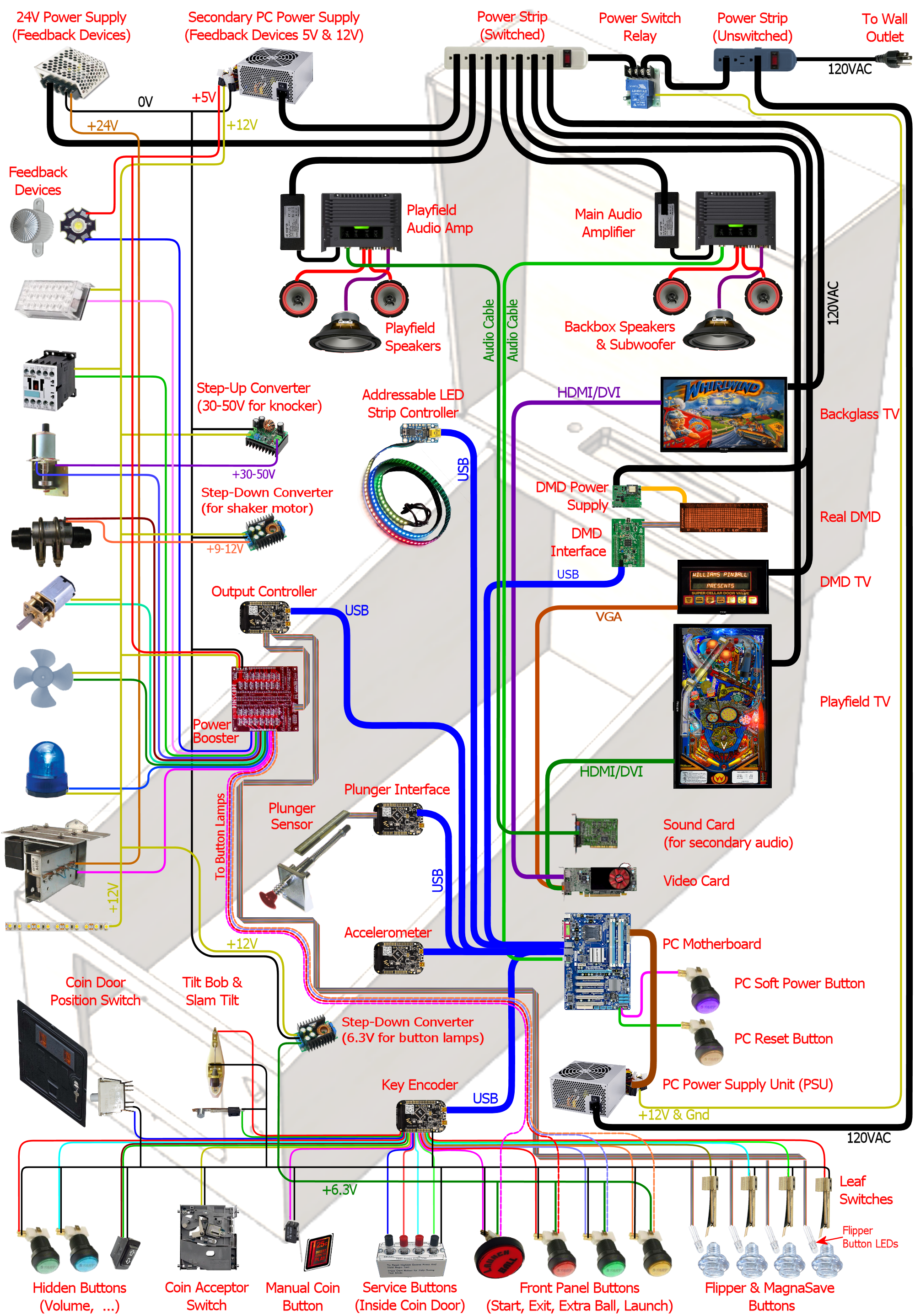
 Start: Essential. Round pushbutton, front panel, top left.
 Exit:
Essential. Round pushbutton, front panel, below Start.
Exit:
Essential. Round pushbutton, front panel, below Start. Coin In: Essential. No standard location, but commonly either
a round pushbutton on the front panel, or repurposing the Coin Reject buttons on the coin door slots.
Coin In: Essential. No standard location, but commonly either
a round pushbutton on the front panel, or repurposing the Coin Reject buttons on the coin door slots.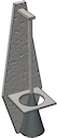 Tilt bob: Essential-ish. Inside the cab.
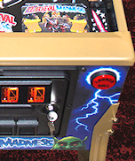 Large round pushbutton, front panel, right.
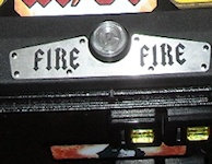 Many newer Stern games (2005 to present) feature this extra button on
top of the lockdown bar, usually centered side to side. (The lockdown
bar is the metal trim piece at the front edge of the machine, so
named because it locks the glass playfield cover into place.) The
button itself is usually a clear flipper button, and usually has a lamp
inside, which lights up when the button can be used to activate a special
feature in the game.
Many newer Stern games (2005 to present) feature this extra button on
top of the lockdown bar, usually centered side to side. (The lockdown
bar is the metal trim piece at the front edge of the machine, so
named because it locks the glass playfield cover into place.) The
button itself is usually a clear flipper button, and usually has a lamp
inside, which lights up when the button can be used to activate a special
feature in the game.
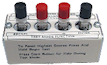 Service
buttons: Nice to have. Inside the coin door.
Service
buttons: Nice to have. Inside the coin door. A few games from the 1990s feature an extra front-panel button labeled
"Extra Ball", "Buy-In", or in a few cases something marketing-ese like
"Super Ball". The button on the real machines is either below the
Start button or below the plunger. It lets you
buy an extra ball for a credit after the last ball ends (which can be
a decent deal if you're close to a replay or close to beating the
high score). Realistically, for virtual play, you'll probably never use
it: why bother "buying" an extra ball when every game is free? Even so,
I included one on my machine mostly for completeness, because I like
a lot of games from the era where this button was common. If you
do include it, it also gives you one more option for mapping special
functions in games with unique buttons.
A few games from the 1990s feature an extra front-panel button labeled
"Extra Ball", "Buy-In", or in a few cases something marketing-ese like
"Super Ball". The button on the real machines is either below the
Start button or below the plunger. It lets you
buy an extra ball for a credit after the last ball ends (which can be
a decent deal if you're close to a replay or close to beating the
high score). Realistically, for virtual play, you'll probably never use
it: why bother "buying" an extra ball when every game is free? Even so,
I included one on my machine mostly for completeness, because I like
a lot of games from the era where this button was common. If you
do include it, it also gives you one more option for mapping special
functions in games with unique buttons.
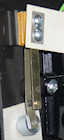 Slam tilt switch:
Neutral. If you have a WPC-style coin door, it will probably have a
slam tilt switch pre-installed. The slam tilt looks like a leaf switch
with a big metal slug attached to the end of the main leaf. It's usually
mounted on the inside of the coin door.
Slam tilt switch:
Neutral. If you have a WPC-style coin door, it will probably have a
slam tilt switch pre-installed. The slam tilt looks like a leaf switch
with a big metal slug attached to the end of the main leaf. It's usually
mounted on the inside of the coin door.
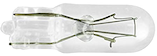
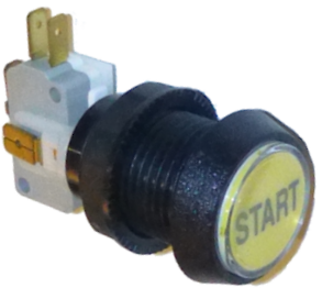
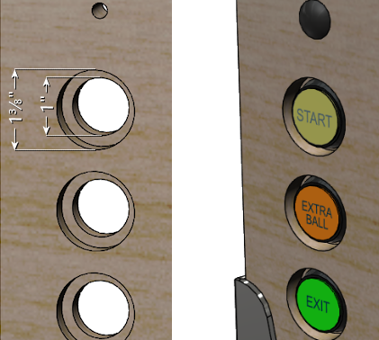
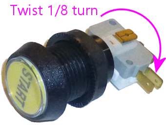
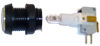
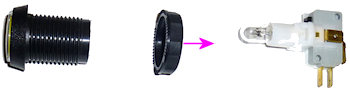
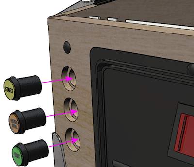
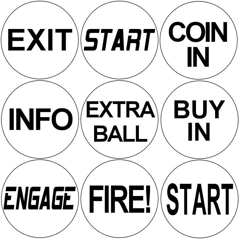
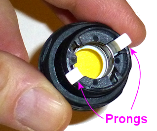
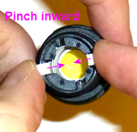
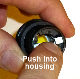
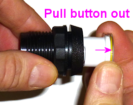
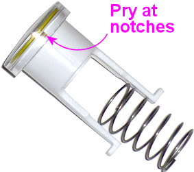
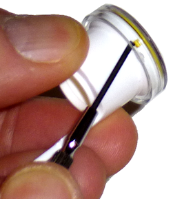
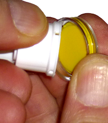
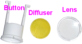
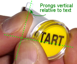
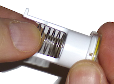
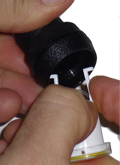

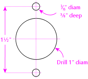
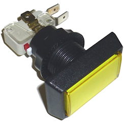
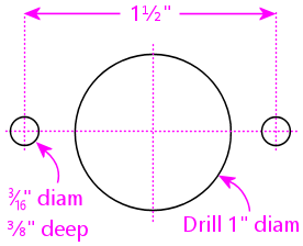
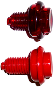
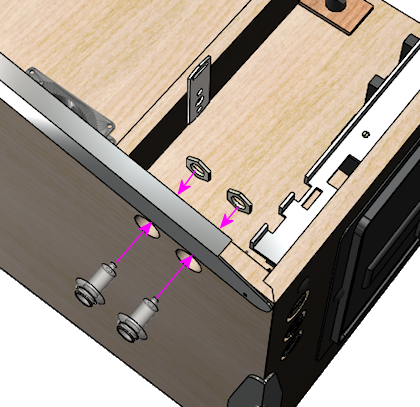
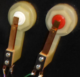
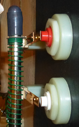
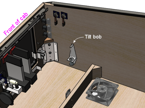 When installing, you should have the machine set up with its legs
attached and leveled, so that the machine is sitting at the same angle
that it'll have in regular use. Angle the tilt bob so that the
pendulum is centered in the ring when at rest.
Adjust the sensitivity of the tilt by moving the plumb bob up or down
on the hanger wire. (Loosen the thumb screws to free the plumb bob to
move up and down; tighten them again when the plumb bob is at the
desired position.) A tilt is signaled when the plumb bob comes into
contact with the surrounding ring, so it increases the tilt
sensitivity when you move the bob upwards on the wire (reducing the
margin between the bob and the ring). You can always come back and
adjust the sensitivity after play-testing if it's too sensitive or too
permissive.
To wire the tilt bob, connect one wire from the keyboard encoder to
the terminal on the upper bracket, and connect the other wire to the
terminal on the ring bracket.
When installing, you should have the machine set up with its legs
attached and leveled, so that the machine is sitting at the same angle
that it'll have in regular use. Angle the tilt bob so that the
pendulum is centered in the ring when at rest.
Adjust the sensitivity of the tilt by moving the plumb bob up or down
on the hanger wire. (Loosen the thumb screws to free the plumb bob to
move up and down; tighten them again when the plumb bob is at the
desired position.) A tilt is signaled when the plumb bob comes into
contact with the surrounding ring, so it increases the tilt
sensitivity when you move the bob upwards on the wire (reducing the
margin between the bob and the ring). You can always come back and
adjust the sensitivity after play-testing if it's too sensitive or too
permissive.
To wire the tilt bob, connect one wire from the keyboard encoder to
the terminal on the upper bracket, and connect the other wire to the
terminal on the ring bracket.
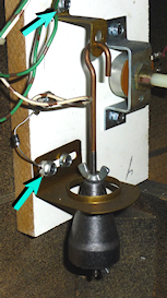 The standard keyboard assignment for the tilt bob in Visual Pinball is
the letter "T" key. But some extra configuration is required! See
"How to configure VP for a tilt bob" in Chapter 8, Nudge & Tilt.
The standard keyboard assignment for the tilt bob in Visual Pinball is
the letter "T" key. But some extra configuration is required! See
"How to configure VP for a tilt bob" in Chapter 8, Nudge & Tilt.
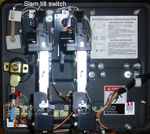 Slam tilt switch in a WPC coin door (interior side of coin door shown).
The WPC doors typically have the switch pre-installed.
If your coin door doesn't already have a built-in slam tilt switch,
and you want to install one separately, look for these parts at the
pinball vendors:
Slam tilt switch in a WPC coin door (interior side of coin door shown).
The WPC doors typically have the switch pre-installed.
If your coin door doesn't already have a built-in slam tilt switch,
and you want to install one separately, look for these parts at the
pinball vendors:
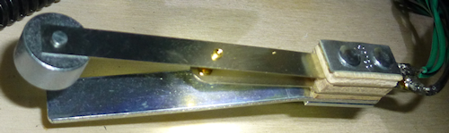 Slam tilt switch with bracket, mounted to cabinet floor.
It'll also work mounted to the front or side walls. Install
near the front of the cab.
Mount the switch to any convenient spot on the cab floor, front wall,
or one of the side walls, close to the front end. It should be within
a foot or so of the front so that it'll be triggered if the front is
lifted and dropped.
To wire, simply connect the wires from your keyboard encoder to the
two leaf switch terminals.
The standard keyboard assignment for a slam tilt in VPinMAME is the
"Home" key (the cursor navigation key).
Slam tilt switch with bracket, mounted to cabinet floor.
It'll also work mounted to the front or side walls. Install
near the front of the cab.
Mount the switch to any convenient spot on the cab floor, front wall,
or one of the side walls, close to the front end. It should be within
a foot or so of the front so that it'll be triggered if the front is
lifted and dropped.
To wire, simply connect the wires from your keyboard encoder to the
two leaf switch terminals.
The standard keyboard assignment for a slam tilt in VPinMAME is the
"Home" key (the cursor navigation key).
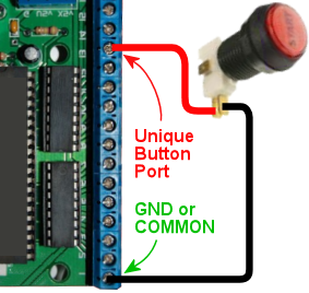
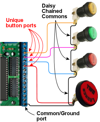
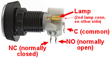

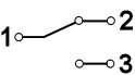 The "1", "2", and "3" lines represent the terminals. The diagonal line in the middle represents the moving contact in the switch. The diagram is telling you that normally, the moving contact connects between 1 and 2, but that when you press the switch, the moving part tilts the other way so that it connects 1 and 3. Connect the Ground/Common wire from your key encoder to terminal "1", and connect the unique button input on the encoder to terminal "3".Note that the numbers themselves aren't what's important here: your switch might use different numbering or different labels entirely. The relationship between the terminals is what's important.
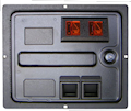 Coin door buttons: If you're using a real pinball coin door, it
probably has several buttons and switches built in:
Coin door buttons: If you're using a real pinball coin door, it
probably has several buttons and switches built in:
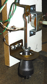 Tilting is a more
interesting topic, since most people haven't had a chance to look
inside a real machine to see exactly how it works. A real machine enforces
the tilt limits with something called a "tilt bob". This is a simple
mechanical sensor that goes back to the early days of pinball.
Tilting is a more
interesting topic, since most people haven't had a chance to look
inside a real machine to see exactly how it works. A real machine enforces
the tilt limits with something called a "tilt bob". This is a simple
mechanical sensor that goes back to the early days of pinball.
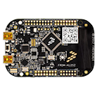 In my opinion, there's
only one type of nudge sensor worth considering: a digital
accelerometer. If you're planning to buy one of the commercial
plunger kits, it'll have one built in. Otherwise, I recommend buying
a Freescale KL25Z (which costs about $15) and installing the Pinscape
software (free). The KL25Z comes fully assembled; all you have to do
is plug in a USB cable. It has an excellent on-board accelerometer,
and the Pinscape software is compatible with VP's nudge input system.
In my opinion, there's
only one type of nudge sensor worth considering: a digital
accelerometer. If you're planning to buy one of the commercial
plunger kits, it'll have one built in. Otherwise, I recommend buying
a Freescale KL25Z (which costs about $15) and installing the Pinscape
software (free). The KL25Z comes fully assembled; all you have to do
is plug in a USB cable. It has an excellent on-board accelerometer,
and the Pinscape software is compatible with VP's nudge input system.
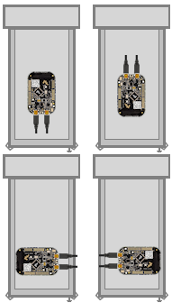
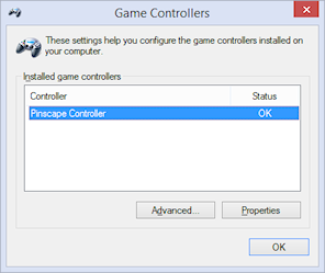

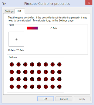


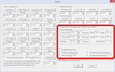
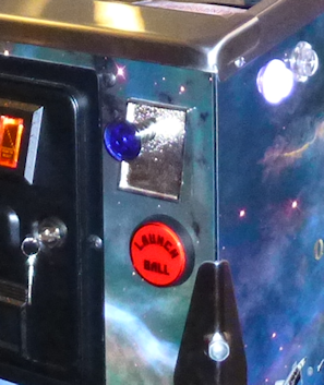 I haven't done a scientific survey of cab builders, but I think the
most common answer to "plunger or launch button?" is "both". With
the plunger in the standard position, there's room directly below
it for a Launch button, at least in a full-sized cab.
I haven't done a scientific survey of cab builders, but I think the
most common answer to "plunger or launch button?" is "both". With
the plunger in the standard position, there's room directly below
it for a Launch button, at least in a full-sized cab.
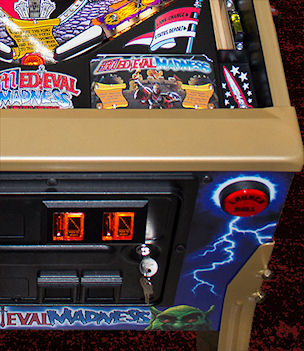 Some pin cab
builders choose to forego a plunger entirely and just use a Launch
Ball button. This is a perfectly viable option functionally, because
all of the PC pinball programs let you operate the on-screen plunger
via the keyboard. And it doesn't make your machine look unrealistic,
since a number of popular real arcade pinball machines also used
button launchers.
Some pin cab
builders choose to forego a plunger entirely and just use a Launch
Ball button. This is a perfectly viable option functionally, because
all of the PC pinball programs let you operate the on-screen plunger
via the keyboard. And it doesn't make your machine look unrealistic,
since a number of popular real arcade pinball machines also used
button launchers.
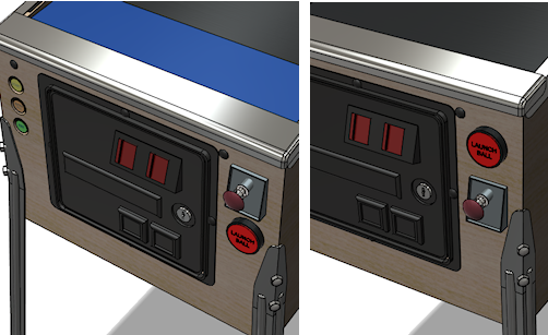
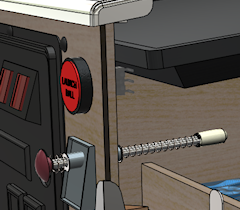
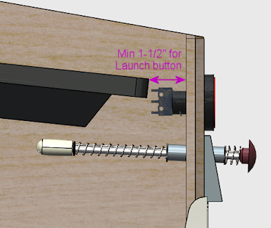
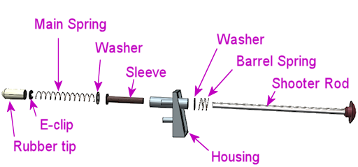
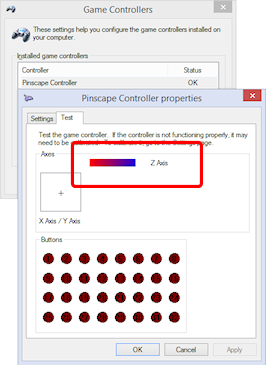
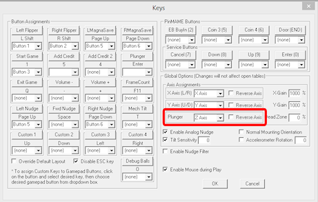
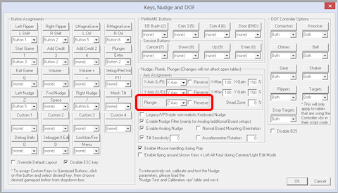
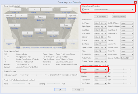
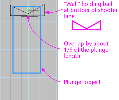
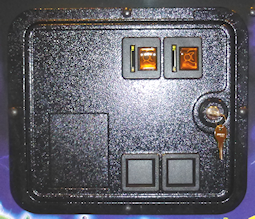 If you want your pin cab
to look authentic, a standard coin door is a must. The coin door has
been a fixture on pinballs since the 1950s, and the design has been
fairly uniform since the 1980s. It's so ubiquitous that I'd consider
it part of what makes a pinball machine look like a pinball machine.
Even if you haven't taken conscious notice of the coin doors on real
machines up until now, you've probably seen them often enough that
you'd notice that something was missing if you didn't include one on
your virtual cab.
If you want your pin cab
to look authentic, a standard coin door is a must. The coin door has
been a fixture on pinballs since the 1950s, and the design has been
fairly uniform since the 1980s. It's so ubiquitous that I'd consider
it part of what makes a pinball machine look like a pinball machine.
Even if you haven't taken conscious notice of the coin doors on real
machines up until now, you've probably seen them often enough that
you'd notice that something was missing if you didn't include one on
your virtual cab.
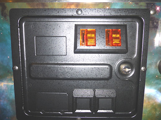 WPC coin door (with my custom Pinscape coin slot inserts!)
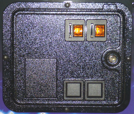 SuzoHapp coin door, also used on most modern Stern machines
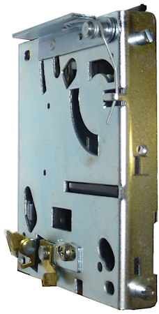
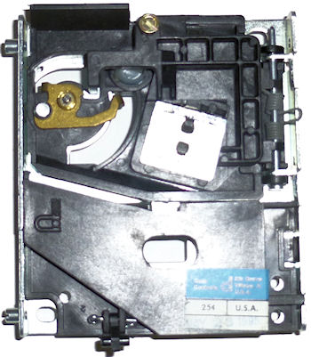
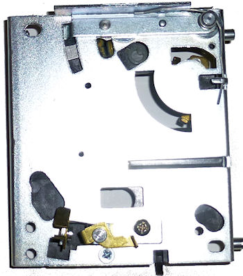
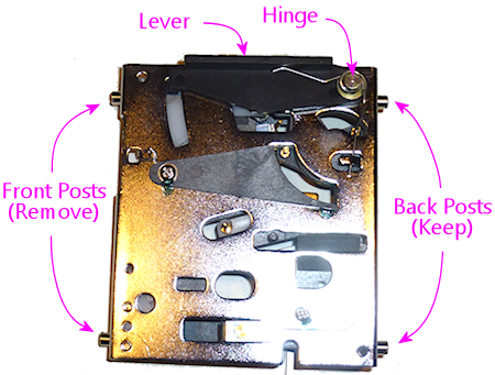
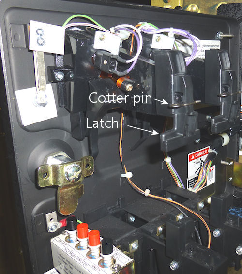
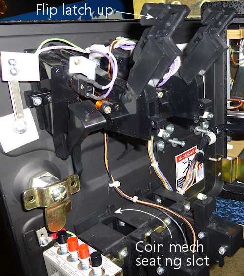
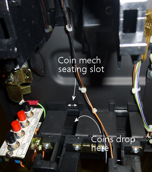
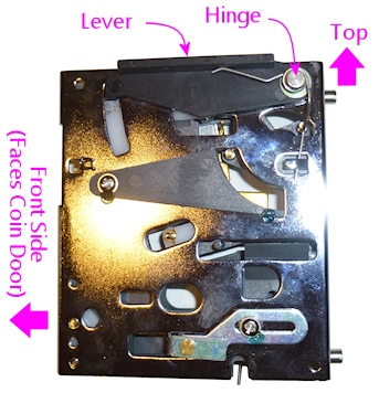
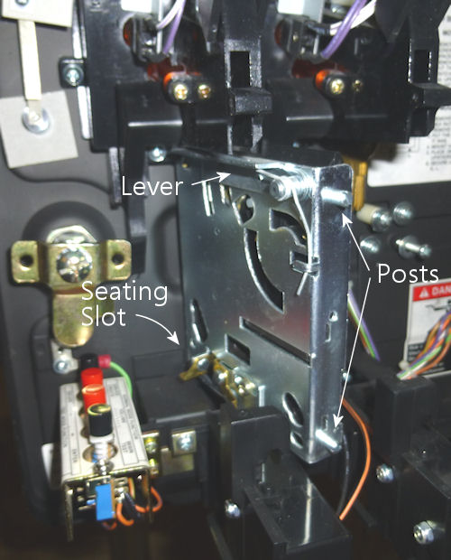
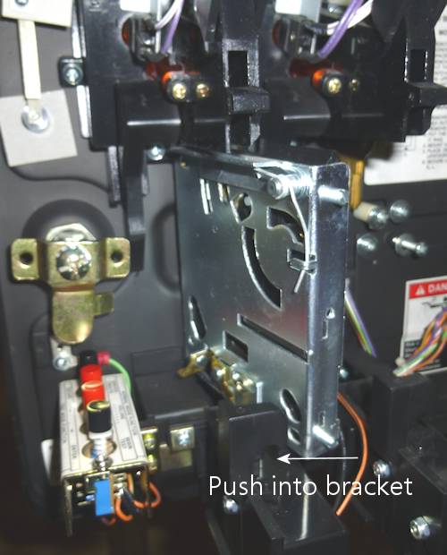
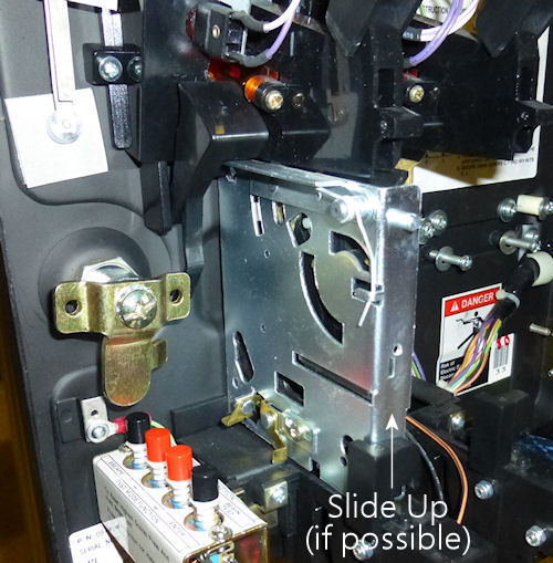
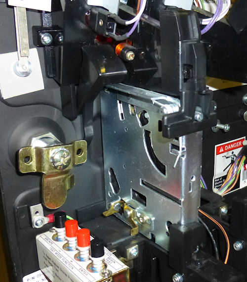
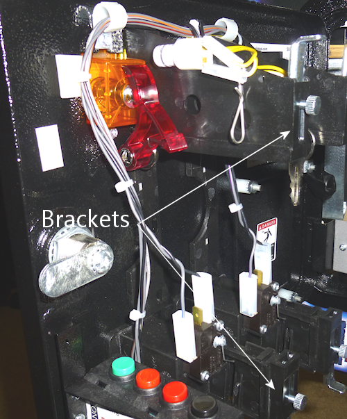
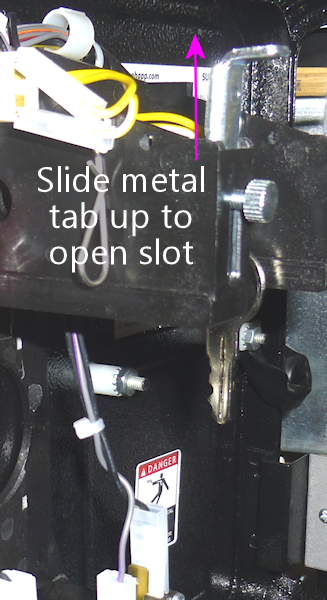
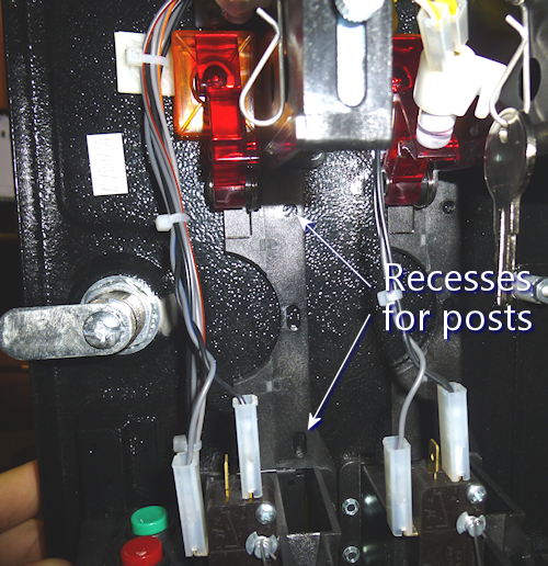
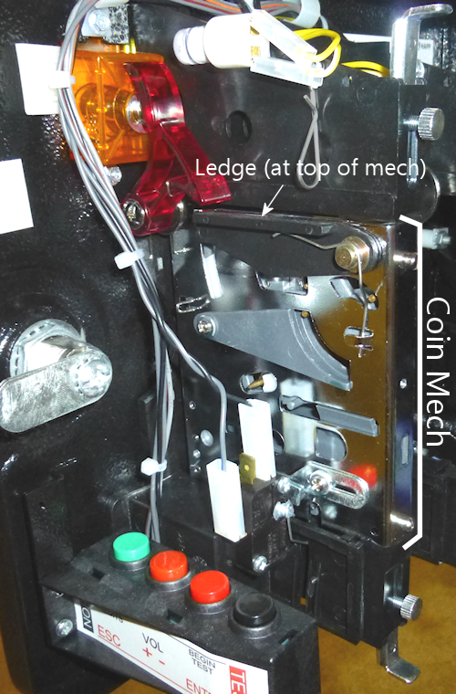
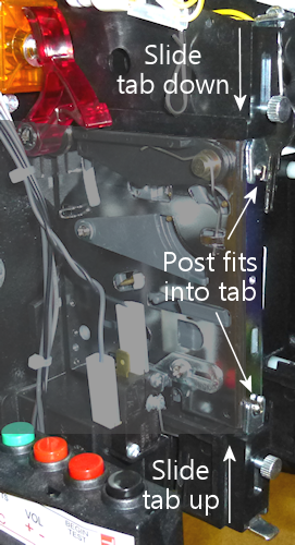
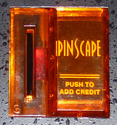 Each coin slot
on the coin door has a "reject" button at the top for clearing coin
jams. These usually come with pre-printed legends indicating the type
of coin accepted, usually "Quarters" or "25¢" for a US door.
Each coin slot
on the coin door has a "reject" button at the top for clearing coin
jams. These usually come with pre-printed legends indicating the type
of coin accepted, usually "Quarters" or "25¢" for a US door.


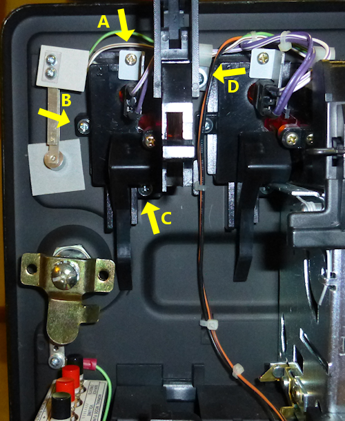
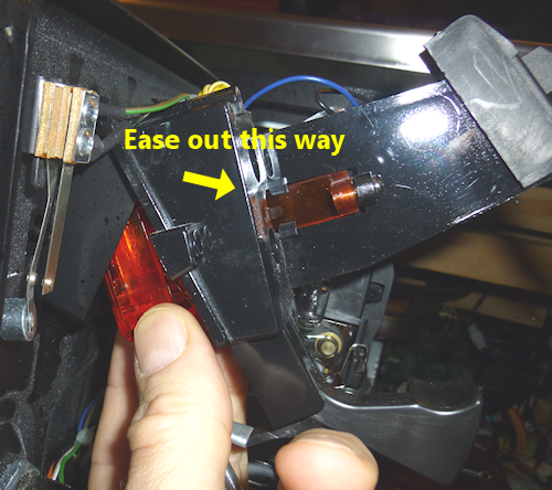
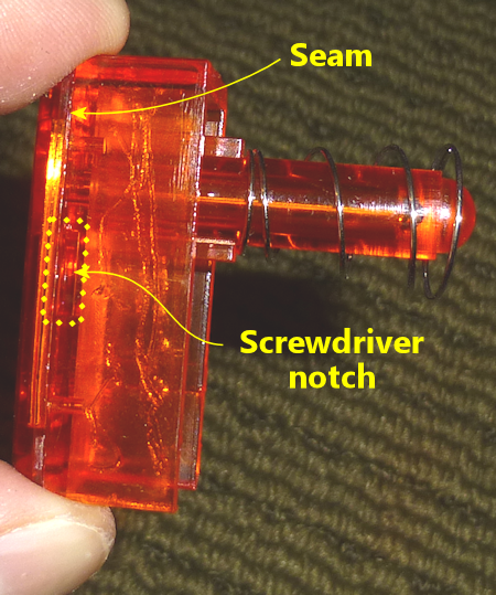
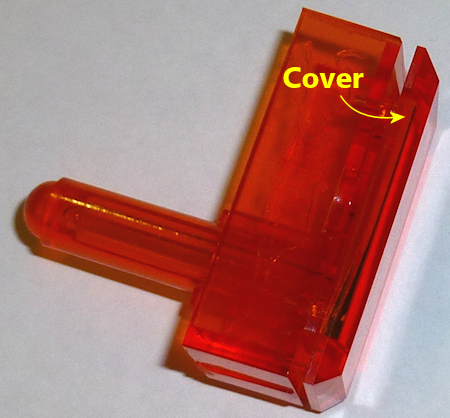
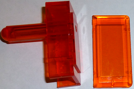
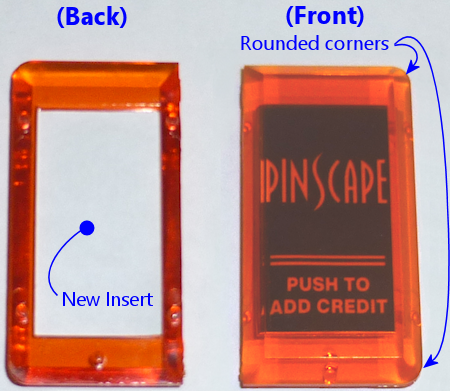
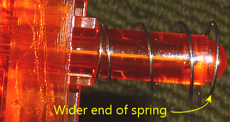
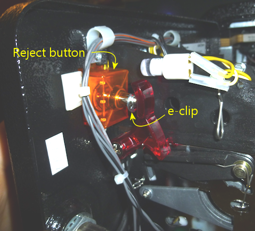
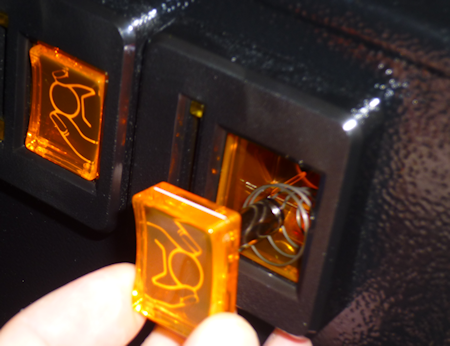
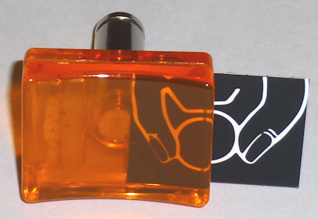
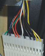 The Williams coin door comes with a pre-wired 13-pin connector of this type:
Molex 09-50-3131. This connector is designed
to plug into a circuit board that has the mating header:
Molex 26-60-4130.
The Williams coin door comes with a pre-wired 13-pin connector of this type:
Molex 09-50-3131. This connector is designed
to plug into a circuit board that has the mating header:
Molex 26-60-4130.
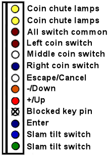
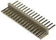 It might seem like
too much work to build a whole separate circuit board just to
accommodate that special coin door plug. The thing that would be a
lot simpler would be to find a mating wire-harness connector that you
could wire to your key encoder and power supply, and then just plug
the two connectors together directly, without any extra circuit boards
in between. There is a way to do this, but it requires a special
adapter plug that serves as a gender changer for the Molex plug,
so that you can plug two of the same Molex plugs together. The
adapter is often called a "Z Connector" because of its shape.
It might seem like
too much work to build a whole separate circuit board just to
accommodate that special coin door plug. The thing that would be a
lot simpler would be to find a mating wire-harness connector that you
could wire to your key encoder and power supply, and then just plug
the two connectors together directly, without any extra circuit boards
in between. There is a way to do this, but it requires a special
adapter plug that serves as a gender changer for the Molex plug,
so that you can plug two of the same Molex plugs together. The
adapter is often called a "Z Connector" because of its shape.
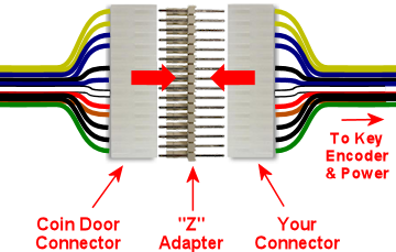
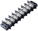 One fairly easy way to deal with the bare wires after
cutting off the connector is to wire them to a screw-terminal block
like the one pictured at right. Look for a terminal block with 12 or
more terminal positions. You can mount the block on the cabinet wall
adjacent to the coin door. Install the coin door first, then connect
each wire from the coin door to one of the screw terminals. Then you
can run a wire from each screw terminals to the corresponding
connector on your key encoder, in the case of the switch wires, or to
the appropriate power connections in the case of the coin chute lamps.
One fairly easy way to deal with the bare wires after
cutting off the connector is to wire them to a screw-terminal block
like the one pictured at right. Look for a terminal block with 12 or
more terminal positions. You can mount the block on the cabinet wall
adjacent to the coin door. Install the coin door first, then connect
each wire from the coin door to one of the screw terminals. Then you
can run a wire from each screw terminals to the corresponding
connector on your key encoder, in the case of the switch wires, or to
the appropriate power connections in the case of the coin chute lamps.
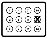 These are connected as follows (refer to the diagram at
right for pin numbering):
These are connected as follows (refer to the diagram at
right for pin numbering):
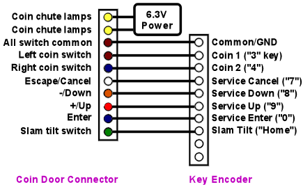
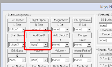
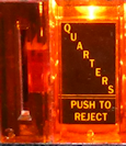 The perfect place for
the "Coin" button, in my opinion, is the Coin Reject buttons at the
top of the coin chutes. You could just add another pushbutton to your
front panel of the same sort as the Start button, but that adds
clutter and makes the machine look less "real", since real pinballs
are almost all very minimalistic about buttons. The Reject buttons
let you hide the Coin button in plain sight, using a button that's
going to be there anyway. It's also an intuitive place for the
virtual Coin button since it serves a coin-related function already.
It's not realistic, of course; an arcade machine obviously isn't going
to provide a button that lets anyone add free credits. But that's
just all the more reason to "hide" the button like this.
The perfect place for
the "Coin" button, in my opinion, is the Coin Reject buttons at the
top of the coin chutes. You could just add another pushbutton to your
front panel of the same sort as the Start button, but that adds
clutter and makes the machine look less "real", since real pinballs
are almost all very minimalistic about buttons. The Reject buttons
let you hide the Coin button in plain sight, using a button that's
going to be there anyway. It's also an intuitive place for the
virtual Coin button since it serves a coin-related function already.
It's not realistic, of course; an arcade machine obviously isn't going
to provide a button that lets anyone add free credits. But that's
just all the more reason to "hide" the button like this.
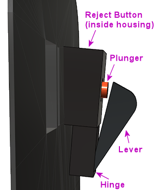
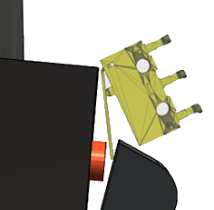
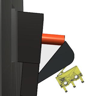
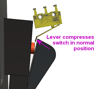
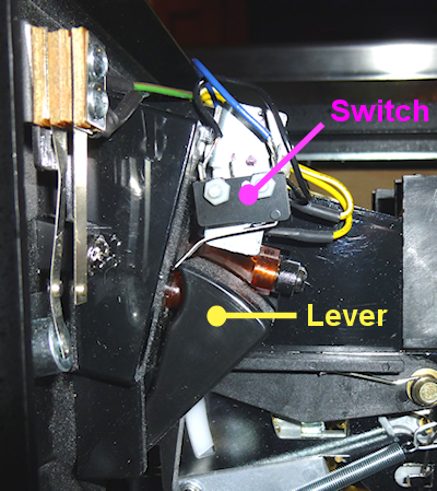
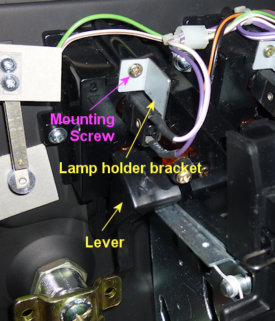
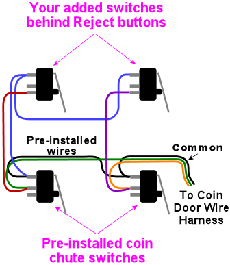
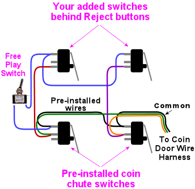
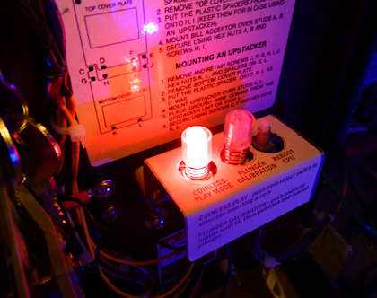
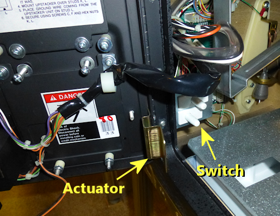
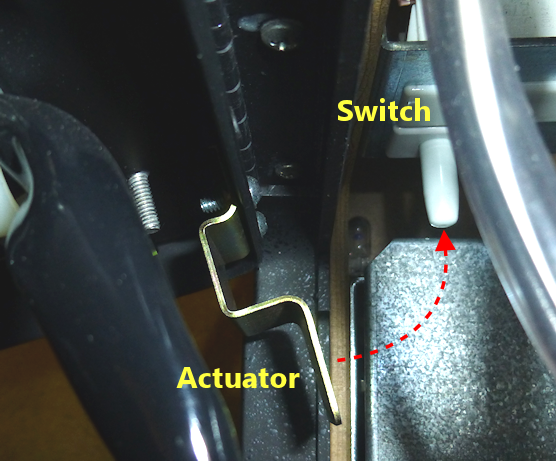
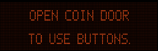
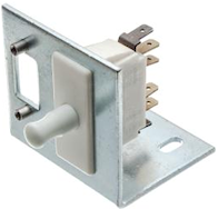 You should install your coin door before installing the switch, so
that you can use the coin door as the alignment guide. You'll
also want to remove the playfield TV or lift it up so that you
can access the inside of the coin door area from above, with the
coin door closed.
You should install your coin door before installing the switch, so
that you can use the coin door as the alignment guide. You'll
also want to remove the playfield TV or lift it up so that you
can access the inside of the coin door area from above, with the
coin door closed.
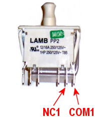
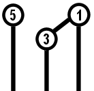
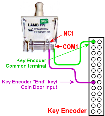
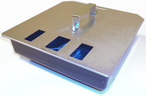 If you install coin
acceptor mechanisms in your coin chutes, you should install a
container under the chutes to capture inserted coins. You don't want
them bouncing around loose inside the cabinet where they could come
into contact with wiring or make other mischief.
If you install coin
acceptor mechanisms in your coin chutes, you should install a
container under the chutes to capture inserted coins. You don't want
them bouncing around loose inside the cabinet where they could come
into contact with wiring or make other mischief.
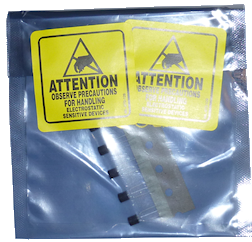
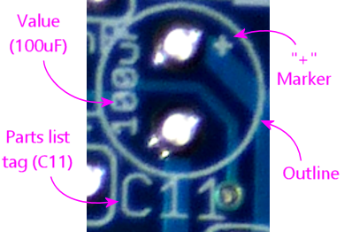
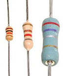
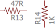
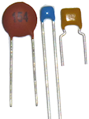


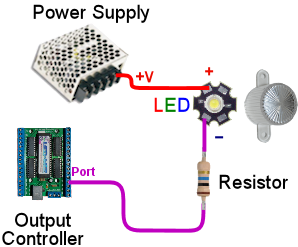
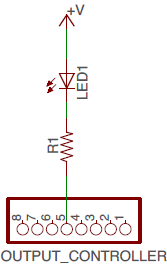


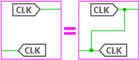
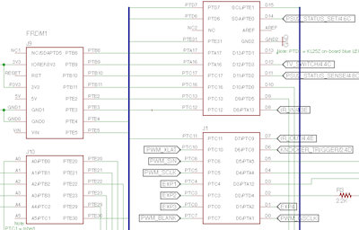

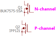
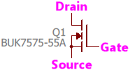


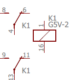
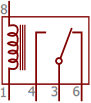
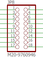
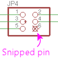
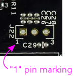
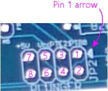

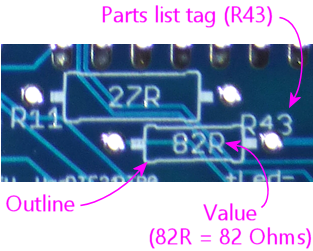
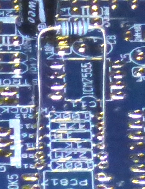
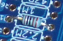
 Resistors are represented on schematics as a jagged lines, as shown at
right. They're usually marked with an Rnumber reference
designator, such as R5 or R10. The "R" is for resistor, and the number is
arbitrary, purely to match up against the parts list. Designators
always have to be unique within the whole schematic, so that each
part can be individually identified. Resistors on schematics are also
usually labeled with the resistance value in Ohms, which we'll come to
shortly. In this case, the "4.7K" label means 4.7 Kilo Ohms = 4,700
Ohms.
Resistors are represented on schematics as a jagged lines, as shown at
right. They're usually marked with an Rnumber reference
designator, such as R5 or R10. The "R" is for resistor, and the number is
arbitrary, purely to match up against the parts list. Designators
always have to be unique within the whole schematic, so that each
part can be individually identified. Resistors on schematics are also
usually labeled with the resistance value in Ohms, which we'll come to
shortly. In this case, the "4.7K" label means 4.7 Kilo Ohms = 4,700
Ohms.
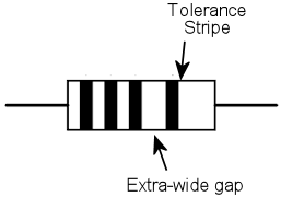
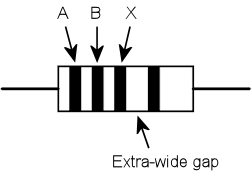
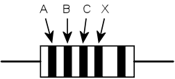
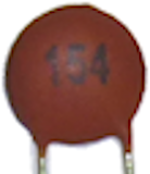
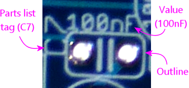
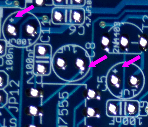
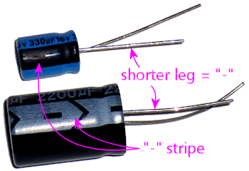
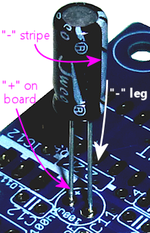
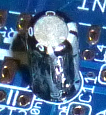

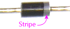
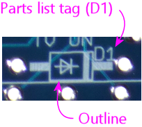

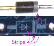
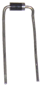
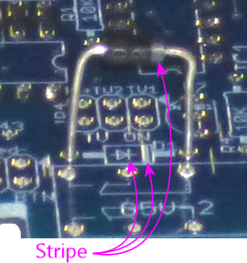
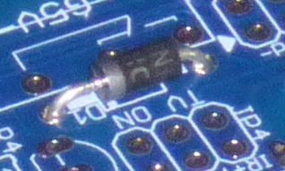
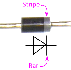
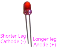
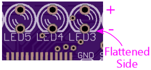
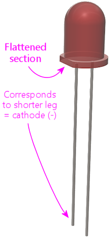

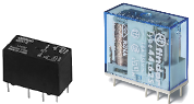
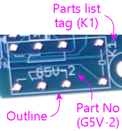
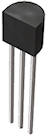
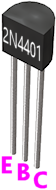
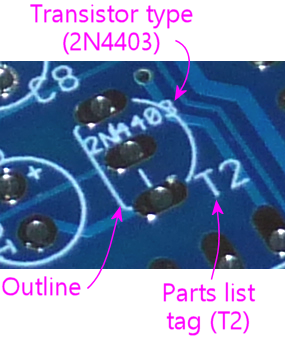
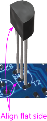
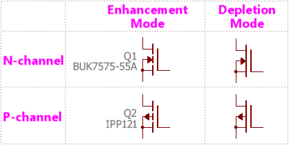

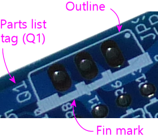
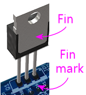
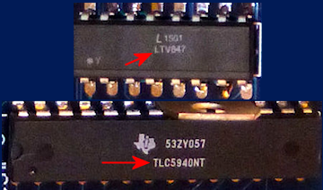
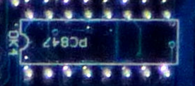
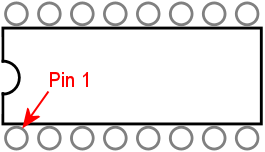
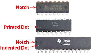
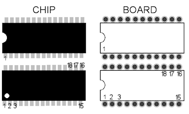
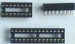
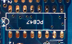
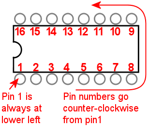
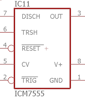
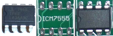
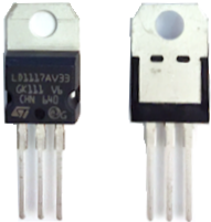

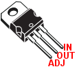
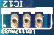
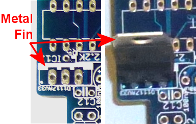
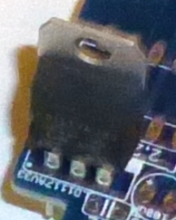
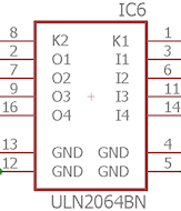

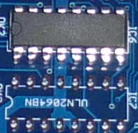
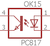
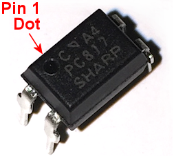
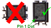
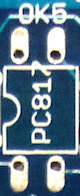
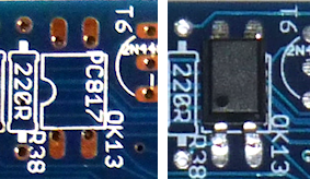
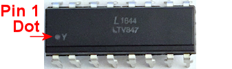
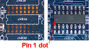
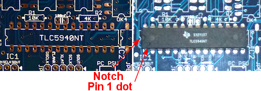
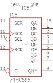
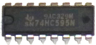
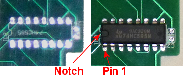
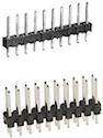
 This is one of the most ubiquitous connectors that you'll see in hobbyist
electronics, and really electronics in general. A pin header is basically
just a row of connector pins sticking up out of a circuit board, to
provide a connection point to the outside world for a group of circuits.
This is one of the most ubiquitous connectors that you'll see in hobbyist
electronics, and really electronics in general. A pin header is basically
just a row of connector pins sticking up out of a circuit board, to
provide a connection point to the outside world for a group of circuits.
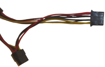
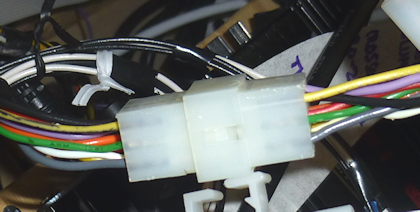
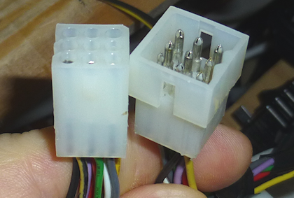
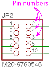
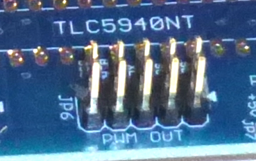
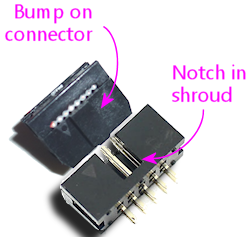
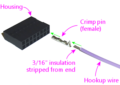
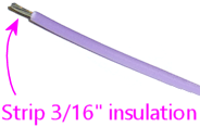
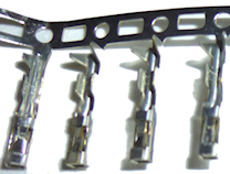
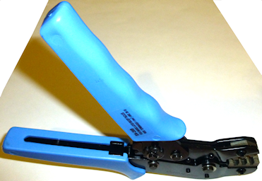
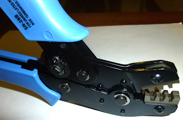
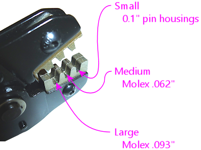
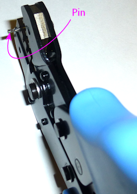
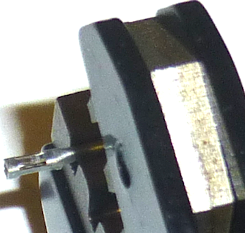
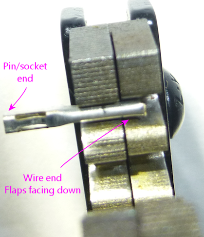
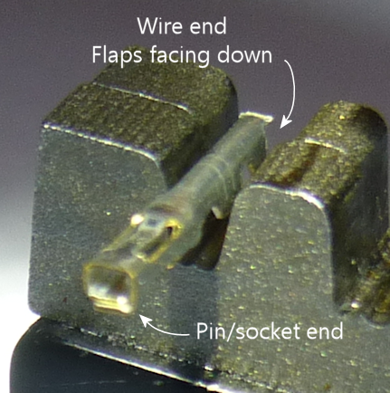

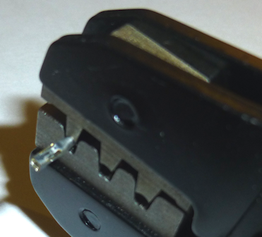
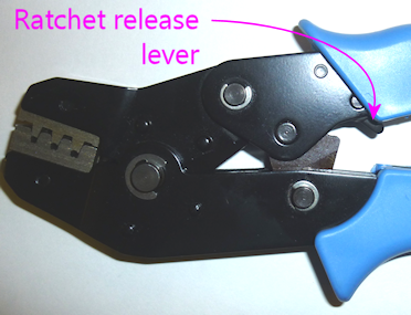
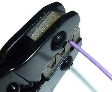
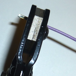
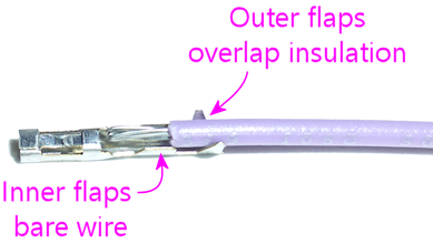
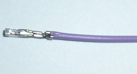
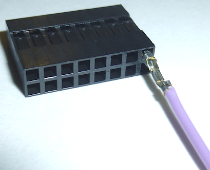
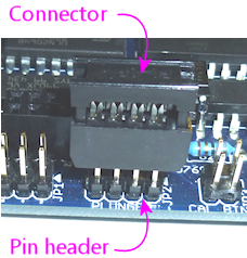

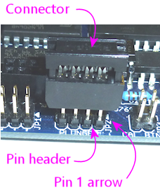
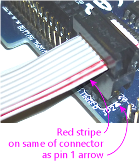
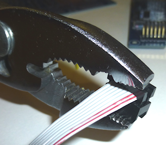
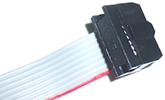
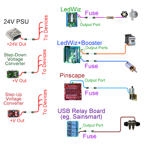


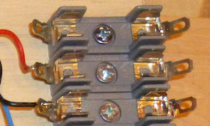 Note that there are several different sizes of cartridge fuses, so you'll need holders that match the size you're using. Here are example holders for the most common sizes (these cover all of the fuses linked in this chapter):These have a screw hole for mounting to just about any surface, so you can mount them directly to your cabinet wall or floor or to a separate piece of plywood that you can later mount in the cabinet. If you're using an output controller, I recommend mounting the controller plus the fuses for all of is outputs on its own plywood carrier. That lets you do all of the initial wiring on your workbench rather than in the confined spaces inside your cab. If you're using an LedWiz or Pinscape board, you'll have a lot of fuses to install, so it makes the work a lot easier.
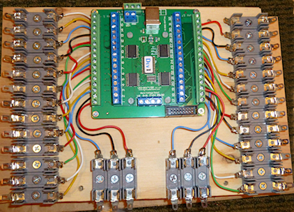 Once it's all set up, you can then mount the whole thing in your cabinet with a couple of screws. This also lets you remove the whole setup later if you ever need to do any repair or upgrade work.
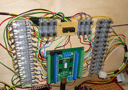 Note that a key element of a modular setup like this is pluggable connectors. You'll want to use some kind of mating plug-and-socket connector to connect all of the wires coming out of the fuses to the devices inside the cabinet. You can see one of the connectors I use in the lower right of the picture above; here's a closeup.
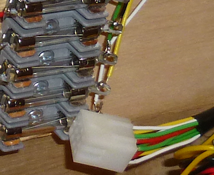 That's a connector from the Molex .062" series, which I found useful for many of the interconnects in my cabinet. There's more information on these and other options in Chapter 27, Connectors. The thing I like about pluggable connectors like this is that they help avoid dumb mistakes. You only have to plan out and wire the connectors once, and from then on it's just a matter of plugging the mating connectors back together any time you have to do any work that involves removing something. You don't have to match up the individual wires again, since they're bundled into connectors that only fit one way.
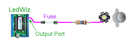 First, connect a wire between the output port on the controller and one end of the fuse. Next, connect a wire from the other end of the fuse to the feedback device (the light, motor, etc). If the device cares about polarity, this is the negative or "ground" terminal on the device.In the diagram above, we used an LED as the example output device, so there's actually an extra step involved, because LEDs usually require resistors (that's a whole separate subject, explained in ). In this case, the resistor goes between the fuse and the LED, so we connect the wire from the fuse to one end of the resistor, and connect a wire from the other end of the resistor to the output device. For anything but an LED, there's no resistor, so the wire from the fuse goes straight to the device.Fuses don't care about polarity, so it doesn't matter which direction it goes. Resistors don't care either.
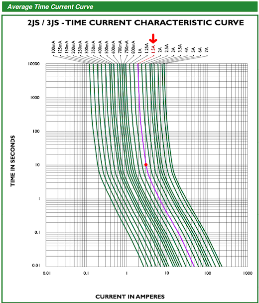 Each green curve represents the current/time relationship for one type of fuse, labeled at the top.Here's the way I use this type of chart to pick a fuse. Let's say we want to pick a fuse for a replay knocker with an AE-26-1200 coil that we're running at 35V. As we calculated above, that gives us 3.2A as the normal operating current for the coil, and as we guesstimated above, we'd like a fuse that blows in perhaps 10-20 seconds. So let's go to the chart, and find the intersection of 10 seconds and 3.2A. I marked that spot with a red dot. That happens to fall right on one of the green lines - if it didn't, it would be between two lines, so we could pick the closest. I highlighted the line we're on to make it easier to follow. Now trace the line to the top of the chart to see which fuse it's for: it's the 1-1/2A (1.5A) fuse.It seems a little strange that we're going to use a 1.5A fuse for a 3A coil, but the amp rating on the fuse is only nominal. The timing chart tells the full story, and in this case the timing chart says that the nominally 1.5A fuse will let our 3 Amps flow for up to about 10 seconds. In case you're still not convinced, I've been running with this fuse protecting my own AE-26-1200 replay coil, and it hasn't ever blown on a false alarm.Since this is such a common coil in virtual pinball machines, I'll save you the trouble of finding the 1.5A version of this family. Here's the part number and a Mouser link: Bel Fuse 3JS 1.5-R TR.Wiring the fuse for a knocker is just like wiring a fuse for any other output device. The fuse goes between the output port on the controller board and the knocker coil. Here's a diagram; we use an LedWiz with booster board as an example, but it's the same for any other type of output controller.
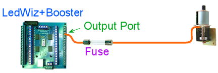 First, run a wire from the output port on the controller board to one end of the fuse. Next, run a wire from the other end of the fuse to the knocker. This connects to the negative side of the knocker coil, usually signified by a black wire. (The coil itself doesn't care about polarity, but it should have a diode attached, and the diode does care.) Fuses have no polarity, so the direction you connect the fuse doesn't matter.
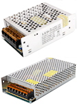 Pin cab builders
often use a mix of power supplies that includes one or more generic,
no-name power supplies from eBay that look similar to the ones shown
at right. These are often sold on eBay as LED strip PSUs or OEM PSUs,
since they're primarily designed for sale to other manufacturers
to embed in consumer devices.
These power supplies might or might not have built-in overload protection. Check the site where you bought your to find out if they say anything about it. Also check to see if it has its own replaceable fuse accessible from the exterior of the case (this is rare).If there's no built-in overload protection, you might want to protect the power supply with a fuse.Choose a fuse that matches the rated maximum output amperage for the unit. If the unit's output limit is only stated in Watts, you can determine the maximum amperage by dividing Watts by Volts, using the voltage on the output side. For example, if your power supply has 12V output and a maximum power output of 48W, the maximum amperage output is 48W/12V = 4A. So you'd choose a 4A fuse.(Earlier, we talked about a 75% rule of thumb, where we use a fuse rated for 75% of the maximum for what we're protecting. That applies when we're protecting a transistor or IC chip. Power supplies shouldn't need this adjustment, since the components they use aren't as vulnerable to brief current surges.)Connect a power supply fuse as shown in the diagram below. (We show a 24V supply as an example, but the principle is the same for any voltage.) Run a wire from the power supply's positive (+) output to one end of the fuse. Connect the other end of the fuse to whatever devices the power supply will be powering.
Pin cab builders
often use a mix of power supplies that includes one or more generic,
no-name power supplies from eBay that look similar to the ones shown
at right. These are often sold on eBay as LED strip PSUs or OEM PSUs,
since they're primarily designed for sale to other manufacturers
to embed in consumer devices.
These power supplies might or might not have built-in overload protection. Check the site where you bought your to find out if they say anything about it. Also check to see if it has its own replaceable fuse accessible from the exterior of the case (this is rare).If there's no built-in overload protection, you might want to protect the power supply with a fuse.Choose a fuse that matches the rated maximum output amperage for the unit. If the unit's output limit is only stated in Watts, you can determine the maximum amperage by dividing Watts by Volts, using the voltage on the output side. For example, if your power supply has 12V output and a maximum power output of 48W, the maximum amperage output is 48W/12V = 4A. So you'd choose a 4A fuse.(Earlier, we talked about a 75% rule of thumb, where we use a fuse rated for 75% of the maximum for what we're protecting. That applies when we're protecting a transistor or IC chip. Power supplies shouldn't need this adjustment, since the components they use aren't as vulnerable to brief current surges.)Connect a power supply fuse as shown in the diagram below. (We show a 24V supply as an example, but the principle is the same for any voltage.) Run a wire from the power supply's positive (+) output to one end of the fuse. Connect the other end of the fuse to whatever devices the power supply will be powering.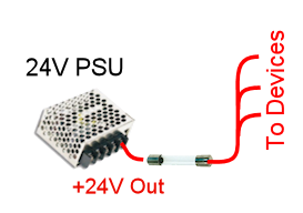
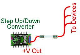
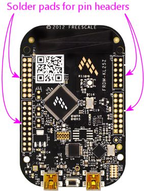
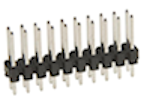
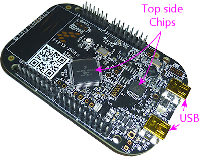
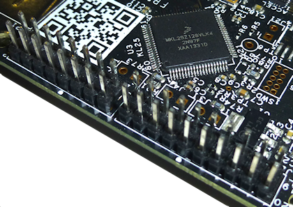
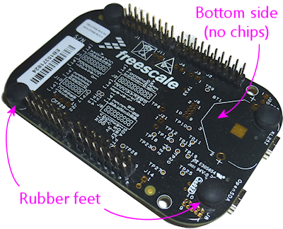
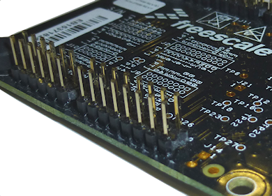
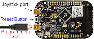 Press and hold the KL25Z reset button.
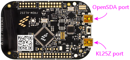
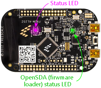
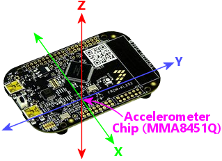
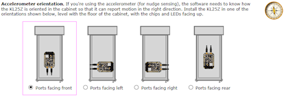
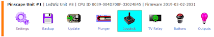
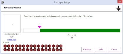
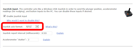
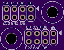
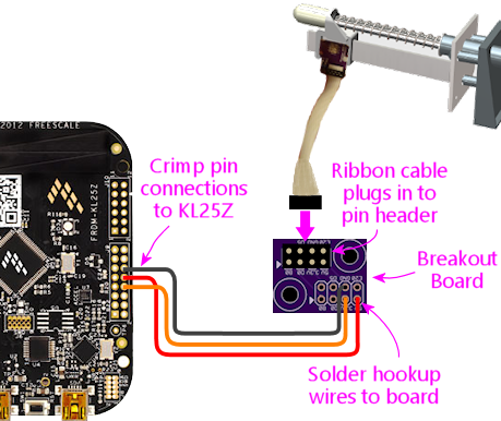
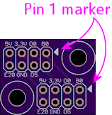
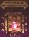 One of the newer sensor option for the Pinscape plunger is an "optical
encoder" chip called the AEDR-8300.
One of the newer sensor option for the Pinscape plunger is an "optical
encoder" chip called the AEDR-8300.
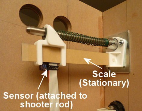
 Sensor bracket. This plastic piece fastens the
sensor to the plunger. It simply fits over the end of
the plunger rod between the e-clip and the spring, so
it's held in place by the spring.
Sensor bracket. This plastic piece fastens the
sensor to the plunger. It simply fits over the end of
the plunger rod between the e-clip and the spring, so
it's held in place by the spring.
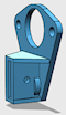 Guide bracket. This plastic piece serves as the
anchor for the guide rail, which holds the optical bar
pattern ("scale") that the sensor scans. This fits
over the metal plate that anchors the screws holding
the ball shooter housing in place.
Guide bracket. This plastic piece serves as the
anchor for the guide rail, which holds the optical bar
pattern ("scale") that the sensor scans. This fits
over the metal plate that anchors the screws holding
the ball shooter housing in place.
 Guide rail. This is a piece of 3mm thick mirrored
acrylic that serves as the guide rail that the sensor moves
across. This fits into the guide bracket and is held in
place with a bolt.
Guide rail. This is a piece of 3mm thick mirrored
acrylic that serves as the guide rail that the sensor moves
across. This fits into the guide bracket and is held in
place with a bolt.
 Printed scale. The bar pattern that the sensor
reads can be printed with an ordinary laser printed on
transparency sheets. Use transparency sheets made for
laser printers, such as 3M CG3300.
Printed scale. The bar pattern that the sensor
reads can be printed with an ordinary laser printed on
transparency sheets. Use transparency sheets made for
laser printers, such as 3M CG3300.
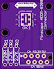 Circuit board. This small printed circuit board holds
the sensor chip, plus a few resistors it needs, and pads for
a ribbon cable to connect to the Pinscape expansion boards.
This fits into the sensor bracket. You can order these
from OSH Park simply
by uploading the EAGLE .brd file.
Circuit board. This small printed circuit board holds
the sensor chip, plus a few resistors it needs, and pads for
a ribbon cable to connect to the Pinscape expansion boards.
This fits into the sensor bracket. You can order these
from OSH Park simply
by uploading the EAGLE .brd file.
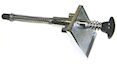 Plunger. Of course, you'll also need a real pinball
plunger. You don't have to fabricate anything for this; you
can just buy a real one. The parts above are
all designed around the Williams/Bally ball shooter assembly,
Williams part no. B-12245. They haven't changed the design since
at least the late 1980s, so if you have an older version, chances
are it'll fit. I think the current Stern plungers are the
same size as well, but I haven't confirmed that.
Plunger. Of course, you'll also need a real pinball
plunger. You don't have to fabricate anything for this; you
can just buy a real one. The parts above are
all designed around the Williams/Bally ball shooter assembly,
Williams part no. B-12245. They haven't changed the design since
at least the late 1980s, so if you have an older version, chances
are it'll fit. I think the current Stern plungers are the
same size as well, but I haven't confirmed that.
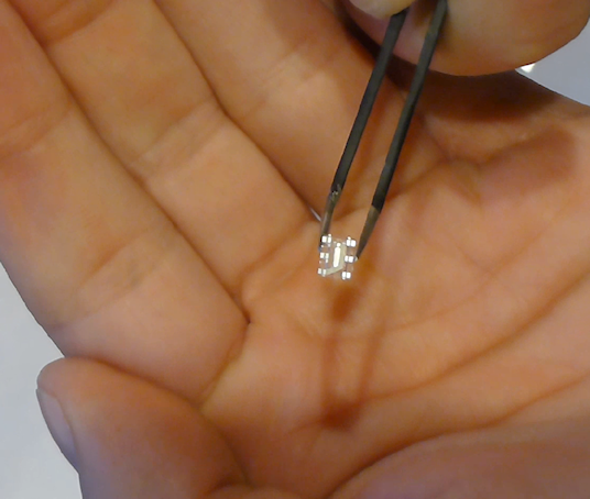
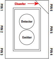
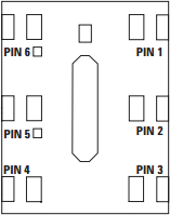
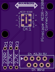
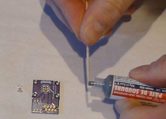
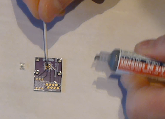
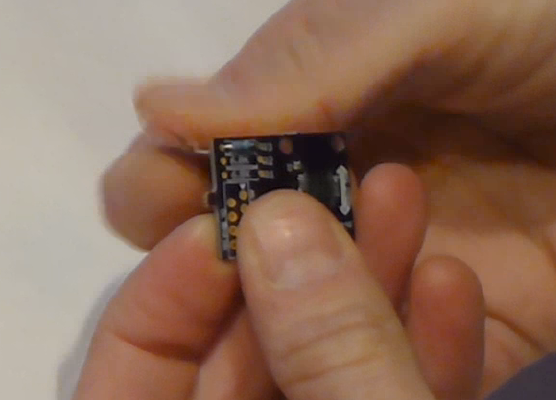 Turn on your soldering iron. Turn the board over. Hold the tip of
the soldering iron against the point where the resistor wire and board
pad meet. The goal is to heat up both pieces of metal, hot enough to
melt the solder. Give it a few moments to heat up, then touch the
solder to the lead/pad junction point you're heating. Let the solder
melt and flow over the joint, then remove the iron. Keep everything
perfectly still for about 5-10 seconds until the solder fully hardens.
Turn on your soldering iron. Turn the board over. Hold the tip of
the soldering iron against the point where the resistor wire and board
pad meet. The goal is to heat up both pieces of metal, hot enough to
melt the solder. Give it a few moments to heat up, then touch the
solder to the lead/pad junction point you're heating. Let the solder
melt and flow over the joint, then remove the iron. Keep everything
perfectly still for about 5-10 seconds until the solder fully hardens.
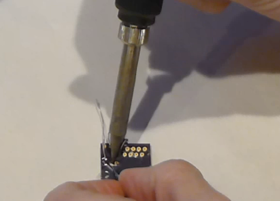 The big rookie mistake in soldering is to focus on the soldering iron
tip when applying solder. What you really want to do is apply the
solder to the metal parts you're trying to join - the resistor wire
and the board pad. Those parts need to be hot enough to melt the
solder on their own. That makes the solder flow onto the parts and
stick to them as it cools. If you apply the solder to the soldering
iron tip, it won't flow properly onto the metal parts you're joining
and won't form a good joint.
Visually inspect the solder joint after you're done and make sure the
solder evenly covers the pad and resistor wire without any gaps. If
you see any gaps, the solder might not have flowed properly onto all
the metal, so re-heat it and apply more solder if necessary. You can
also wiggle the resistor and make sure the wire doesn't move at all in
the joint.
Now you can trim the resistor wire with wire cutters. Cut off the
excess lead past the solder bubble.
The big rookie mistake in soldering is to focus on the soldering iron
tip when applying solder. What you really want to do is apply the
solder to the metal parts you're trying to join - the resistor wire
and the board pad. Those parts need to be hot enough to melt the
solder on their own. That makes the solder flow onto the parts and
stick to them as it cools. If you apply the solder to the soldering
iron tip, it won't flow properly onto the metal parts you're joining
and won't form a good joint.
Visually inspect the solder joint after you're done and make sure the
solder evenly covers the pad and resistor wire without any gaps. If
you see any gaps, the solder might not have flowed properly onto all
the metal, so re-heat it and apply more solder if necessary. You can
also wiggle the resistor and make sure the wire doesn't move at all in
the joint.
Now you can trim the resistor wire with wire cutters. Cut off the
excess lead past the solder bubble.
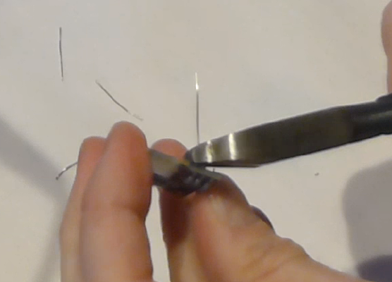
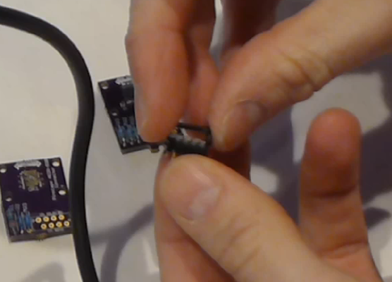 Pop the connector onto the board through the marked holes. Note that
it only fits in one direction: there's a little plastic peg on one side
that has to fit into the corresponding hole on the board. If you can't
get the connector to fit properly, try rotating it 180° in case you
have the peg on the wrong side.
Pop the connector onto the board through the marked holes. Note that
it only fits in one direction: there's a little plastic peg on one side
that has to fit into the corresponding hole on the board. If you can't
get the connector to fit properly, try rotating it 180° in case you
have the peg on the wrong side.
 Flip the board over and solder the pins from the back side of the
board. This is just like soldering the resistor leads. (Except that
there's no excess wire to clip in this case.)
Now it's time to attach the cable. This connector is of the "IDC"
type, which stands for Insulation Displacement Connector, which means
that it's designed to pierce the cable insulation when you press the
cable into it. These connectors are designed to do most of the work
for you, so don't worry if you haven't done this before.
Grab the top "clip" piece for the connector that you set aside
earlier. Position it loosely on top of the base. You can see
that it slides into latches on either side. Don't push it down all
the way yet; leave a gap big enough for the cable.
Flip the board over and solder the pins from the back side of the
board. This is just like soldering the resistor leads. (Except that
there's no excess wire to clip in this case.)
Now it's time to attach the cable. This connector is of the "IDC"
type, which stands for Insulation Displacement Connector, which means
that it's designed to pierce the cable insulation when you press the
cable into it. These connectors are designed to do most of the work
for you, so don't worry if you haven't done this before.
Grab the top "clip" piece for the connector that you set aside
earlier. Position it loosely on top of the base. You can see
that it slides into latches on either side. Don't push it down all
the way yet; leave a gap big enough for the cable.
 Now slip the cable into the gap. If your cable has a stripe (usually
red) down one edge, put that on the side with the triangle/arrow
printed on the circuit boards - that's pin #1. The red stripe will
make it easier to identify the corresponding pin #1 at the other end.
If your cable doesn't have a stripe, I'd strongly recommend adding a
stripe with a red marker. Use an oil-based ink marker -
water-based inks won't stick to the plastic insulation. Draw the
stripe down the whole length of the cable along one side (it doesn't
matter which one; you just pick one as the "pin 1" side).
The cable should just barely fit into the gap. This is part of the
design, to ensure that the cable is positioned properly. Let the end
of the cable extend about 1/4" past the clip.
Once you have it positioned properly, get out some pliers. (There's a
specialized IDC crimper tool for this job, but ordinary pliers will
work if you're careful.) Carefully apply pressure to the top of the
clip. Start at one end, push it down just a little bit there, then
gradually move to the other end. Work your way back and forth a few
times until the clip is all the way down and snaps into the locks.
You have to be careful not to do this all at once, since the locks
aren't strong enough if the pressure is too lopsided.
Now slip the cable into the gap. If your cable has a stripe (usually
red) down one edge, put that on the side with the triangle/arrow
printed on the circuit boards - that's pin #1. The red stripe will
make it easier to identify the corresponding pin #1 at the other end.
If your cable doesn't have a stripe, I'd strongly recommend adding a
stripe with a red marker. Use an oil-based ink marker -
water-based inks won't stick to the plastic insulation. Draw the
stripe down the whole length of the cable along one side (it doesn't
matter which one; you just pick one as the "pin 1" side).
The cable should just barely fit into the gap. This is part of the
design, to ensure that the cable is positioned properly. Let the end
of the cable extend about 1/4" past the clip.
Once you have it positioned properly, get out some pliers. (There's a
specialized IDC crimper tool for this job, but ordinary pliers will
work if you're careful.) Carefully apply pressure to the top of the
clip. Start at one end, push it down just a little bit there, then
gradually move to the other end. Work your way back and forth a few
times until the clip is all the way down and snaps into the locks.
You have to be careful not to do this all at once, since the locks
aren't strong enough if the pressure is too lopsided.
 When you're done, the clip should be fully flush with the sides
locked into the latches. You'll be able to see the insulation
poking into the holes on the top of the clip.
When you're done, the clip should be fully flush with the sides
locked into the latches. You'll be able to see the insulation
poking into the holes on the top of the clip.
 Finally, install the IDC connector at the other end. This is the plug
that connects to the expansion board header. This is almost exactly
the same as assembling the first connector; the only difference is
that there's nothing to solder this time.
The one thing to be careful about is to line up pin #1 on the plug
with the pin #1 wire in the cable. On the plug, you should find a
small triangle or arrow at one corner. That's the pin #1 side. If
you already identified pin #1 with a red stripe on the cable, make
sure the stripe is on the pin #1 side of the plug. Pin #1 on the
sensor board corresponds to pin #1 on the expansion board plunger
header, which is marked on the expansion board with an arrow. Just
line up the pin #1 markings down the whole chain and everything will
communicate properly.
Finally, install the IDC connector at the other end. This is the plug
that connects to the expansion board header. This is almost exactly
the same as assembling the first connector; the only difference is
that there's nothing to solder this time.
The one thing to be careful about is to line up pin #1 on the plug
with the pin #1 wire in the cable. On the plug, you should find a
small triangle or arrow at one corner. That's the pin #1 side. If
you already identified pin #1 with a red stripe on the cable, make
sure the stripe is on the pin #1 side of the plug. Pin #1 on the
sensor board corresponds to pin #1 on the expansion board plunger
header, which is marked on the expansion board with an arrow. Just
line up the pin #1 markings down the whole chain and everything will
communicate properly.
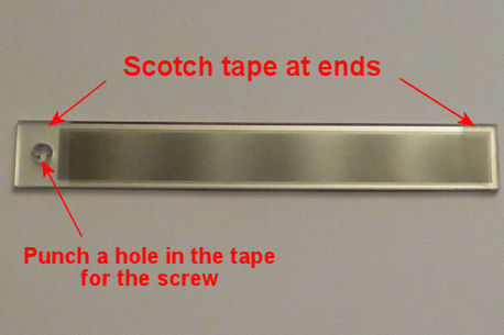 Attach the circuit board to the 3D-printed sensor bracket. Place it with
the sensor facing outward and the ribbon cable or wires at the bottom.
Secure it with four small machine screws and nuts. I recommend M2x8mm or M2x10mm,
or #2x⅜". Nylon parts are ideal here. Insert the screws from the
component side of the board so that the nuts are on the back of the bracket.
Attach the circuit board to the 3D-printed sensor bracket. Place it with
the sensor facing outward and the ribbon cable or wires at the bottom.
Secure it with four small machine screws and nuts. I recommend M2x8mm or M2x10mm,
or #2x⅜". Nylon parts are ideal here. Insert the screws from the
component side of the board so that the nuts are on the back of the bracket.
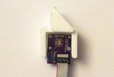 If you already fully installed your plunger, I'm afraid you're going
to have to take it back apart at this point. Remove the e-clip that's
holding the main spring in place (a pair of pliers is helpful: first
hold the spring back so that it's not pressing against the clip, then
grab the back edge of the clip with the pliers and pull it off). Slip
the spring off. Now remove the top two screws from the
housing. Leave the bottom screw in place.
If you haven't already installed your plunger, it's time to do that.
Insert the housing through the opening in the front of the cabinet.
Slip the mounting plate over it, aligning the screw holes. Screw
the bottom screw only into the housing and tighten.
Leave the top two screws out for now. Slip the barrel spring onto
the shooter rod, then add a washer. Make sure the nylon sleeve
is installed in the housing, then slide the rod into the housing.
Add the second washer on the inside.
If you already fully installed your plunger, I'm afraid you're going
to have to take it back apart at this point. Remove the e-clip that's
holding the main spring in place (a pair of pliers is helpful: first
hold the spring back so that it's not pressing against the clip, then
grab the back edge of the clip with the pliers and pull it off). Slip
the spring off. Now remove the top two screws from the
housing. Leave the bottom screw in place.
If you haven't already installed your plunger, it's time to do that.
Insert the housing through the opening in the front of the cabinet.
Slip the mounting plate over it, aligning the screw holes. Screw
the bottom screw only into the housing and tighten.
Leave the top two screws out for now. Slip the barrel spring onto
the shooter rod, then add a washer. Make sure the nylon sleeve
is installed in the housing, then slide the rod into the housing.
Add the second washer on the inside.
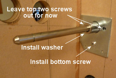 Slip the 3D-printed scale bracket over the shooter rod. It
fits over the shooter rod holder in the housing, and the screw
holes align with the screw holes in the housing.
Slip the 3D-printed scale bracket over the shooter rod. It
fits over the shooter rod holder in the housing, and the screw
holes align with the screw holes in the housing.

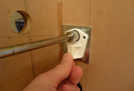 Install the two screws. Don't overtighten, to avoid stressing
the plastic.
Install the two screws. Don't overtighten, to avoid stressing
the plastic.
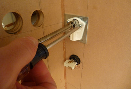 Pop the scale/guide into the slot in the bracket, with the
printed side facing the cabinet wall.
Fasten it with a small bolt and nut through the provided hole in the
bracket. Any nut/bolt that fits will work; an M3x12mm or #4x½"
should work well. I'd recommend a nylon bolt and nut if you have them
handy. In any case, don't overtighten; this one doesn't have to
handle much force, so just make it tight enough that it won't work
itself loose.
Pop the scale/guide into the slot in the bracket, with the
printed side facing the cabinet wall.
Fasten it with a small bolt and nut through the provided hole in the
bracket. Any nut/bolt that fits will work; an M3x12mm or #4x½"
should work well. I'd recommend a nylon bolt and nut if you have them
handy. In any case, don't overtighten; this one doesn't have to
handle much force, so just make it tight enough that it won't work
itself loose.
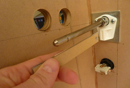
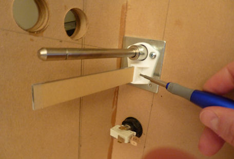 Slip the spring onto the shooter rod.
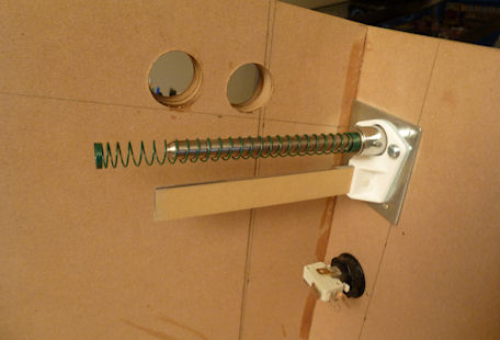 Slide the assembled sensor bracket onto both the shooter rod and the
guide rail. The round hole in the top fits over the shooter rod and
the slits fit over the guide rail. You'll probably want to compress
the spring with one hand while sliding the bracket onto the rod.
Once it's in place, keep holding the bracket back (compressing
the spring) and slip the e-ring into its slot on the shooter rod.
Pop it into place with a pair of pliers. You can now gently release
the spring tension so that the spring pushes the sensor bracket
against the e-clip. This is the final working configuration.
Slide the assembled sensor bracket onto both the shooter rod and the
guide rail. The round hole in the top fits over the shooter rod and
the slits fit over the guide rail. You'll probably want to compress
the spring with one hand while sliding the bracket onto the rod.
Once it's in place, keep holding the bracket back (compressing
the spring) and slip the e-ring into its slot on the shooter rod.
Pop it into place with a pair of pliers. You can now gently release
the spring tension so that the spring pushes the sensor bracket
against the e-clip. This is the final working configuration.
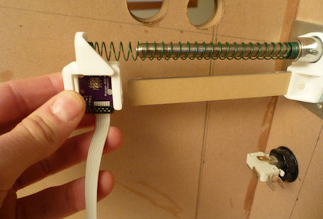
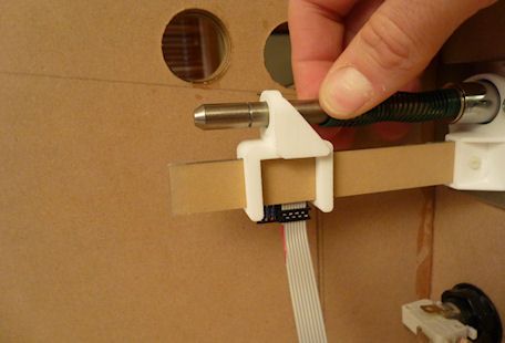
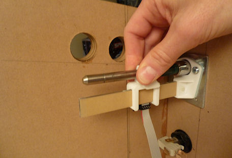
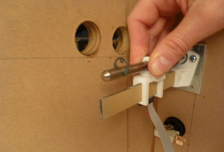
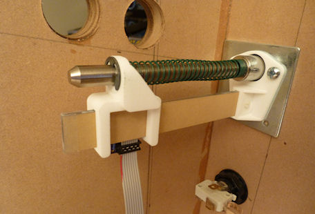
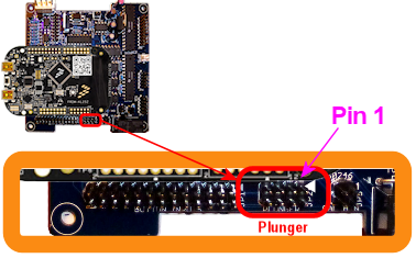 Standalone KL25Z: If you're using the plunger sensor breakout
board as recomended, just plug the ribbon cable connector into the
header on the breakout board. Be sure pin 1 on the plug corresponds
to pin 1 on the board, which is marked with a little white triangle
printed next to the header.
Standalone KL25Z: If you're using the plunger sensor breakout
board as recomended, just plug the ribbon cable connector into the
header on the breakout board. Be sure pin 1 on the plug corresponds
to pin 1 on the board, which is marked with a little white triangle
printed next to the header.
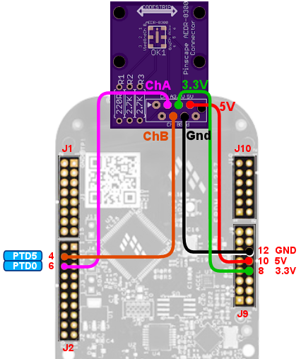 Note that the two GPIO ports, PTD0 and PTD5, are only suggestions. If
you're already using these ports for some other function, you can
assign the sensor inputs to other ports using the Config Tool.
However, note that only ports with "PTA" or "PTD" prefixes can be used
for these. (The inputs have to be PTA or PTD ports because only those
ports are capable of generating interrupts on the KL25Z. The Pinscape
firmware needs interrupt capability on the inputs to process the
signals from this sensor.)
(The power and ground wires aren't configurable. Connect those as
shown.)
In case you want to set up your own custom connector for the
ribbon cable, here's how the pins on the expansion board end
of the ribbon cable connector are arranged:
Note that the two GPIO ports, PTD0 and PTD5, are only suggestions. If
you're already using these ports for some other function, you can
assign the sensor inputs to other ports using the Config Tool.
However, note that only ports with "PTA" or "PTD" prefixes can be used
for these. (The inputs have to be PTA or PTD ports because only those
ports are capable of generating interrupts on the KL25Z. The Pinscape
firmware needs interrupt capability on the inputs to process the
signals from this sensor.)
(The power and ground wires aren't configurable. Connect those as
shown.)
In case you want to set up your own custom connector for the
ribbon cable, here's how the pins on the expansion board end
of the ribbon cable connector are arranged:
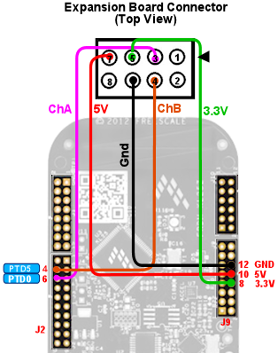
 ).
If you see any warnings, click on the icon for details. In most
cases, the problem will be that you've assigned the same pin to
multiple functions. If so, go to the other place the pin is
assigned, and clear that entry by setting it to "Not Connected".
If the software setup looks okay, check the physical wiring. Inspect
each wire and make sure that it goes to the proper pin on each end
(KL25Z and sensor board). Check that each GPIO port assignment on the
settings page matches up with the physical pin on the KL25Z and
connects to the corresponding terminal on the sensor board.
).
If you see any warnings, click on the icon for details. In most
cases, the problem will be that you've assigned the same pin to
multiple functions. If so, go to the other place the pin is
assigned, and clear that entry by setting it to "Not Connected".
If the software setup looks okay, check the physical wiring. Inspect
each wire and make sure that it goes to the proper pin on each end
(KL25Z and sensor board). Check that each GPIO port assignment on the
settings page matches up with the physical pin on the KL25Z and
connects to the corresponding terminal on the sensor board.
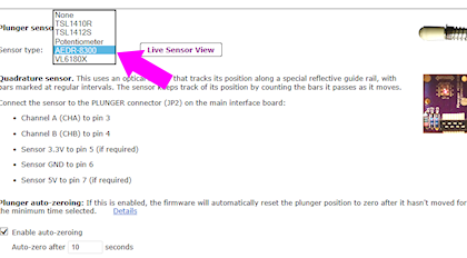
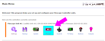
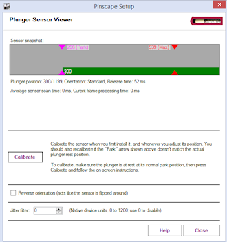
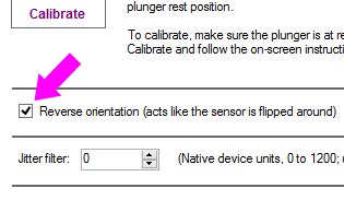
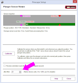
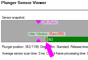
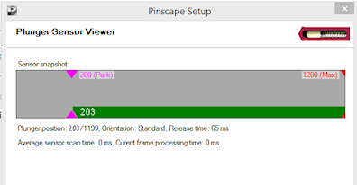
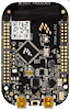 Standalone KL25Z: One wire from each button goes to the "GND" pin
on the KL25Z. The other wire goes to the pin for the GPIO port that
you assigned to the button in the Config Tool.
Standalone KL25Z: One wire from each button goes to the "GND" pin
on the KL25Z. The other wire goes to the pin for the GPIO port that
you assigned to the button in the Config Tool.
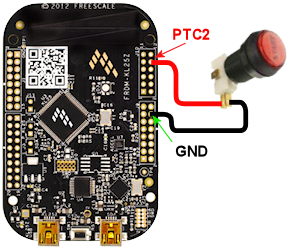
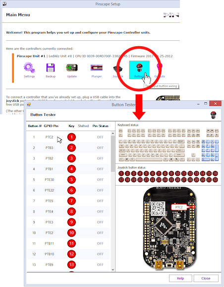
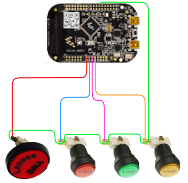
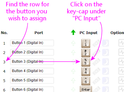
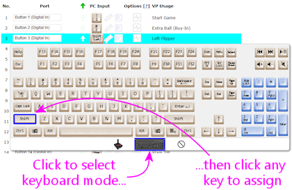
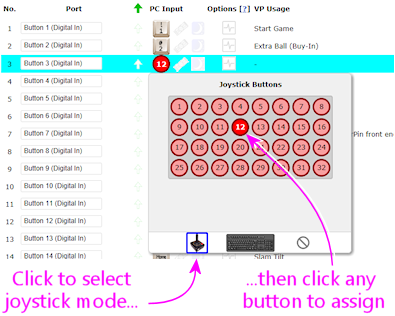
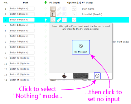
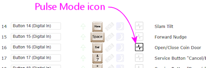
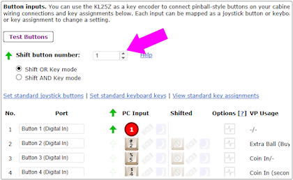
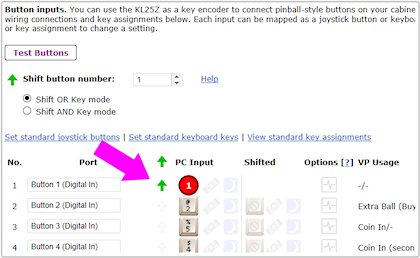
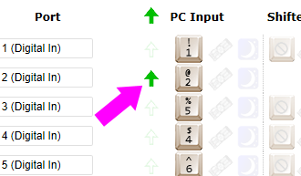
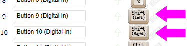
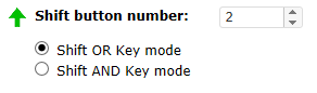
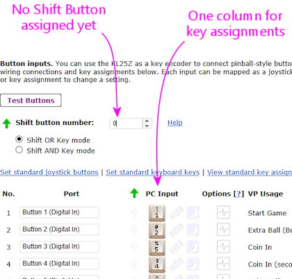
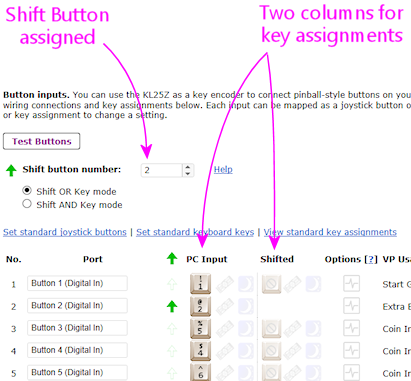
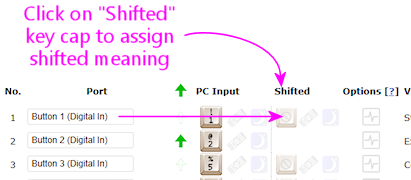
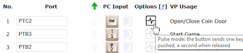
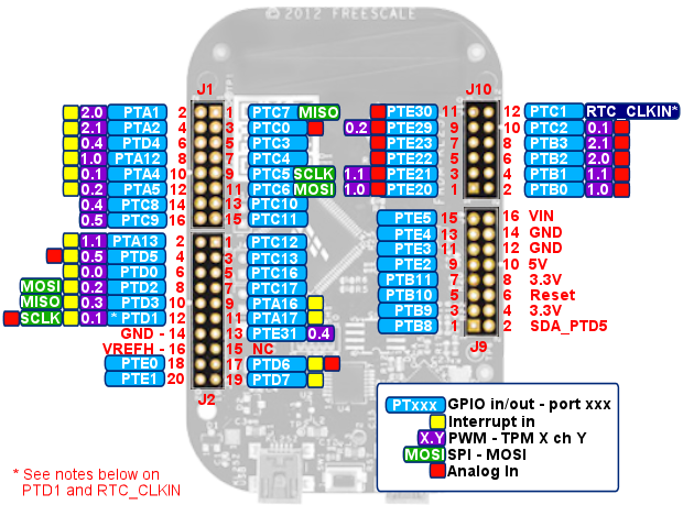
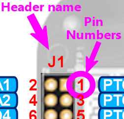 The diagram above shows all of the KL25Z's pin connections,
labeled by their "header" name and "pin number".
The diagram above shows all of the KL25Z's pin connections,
labeled by their "header" name and "pin number".
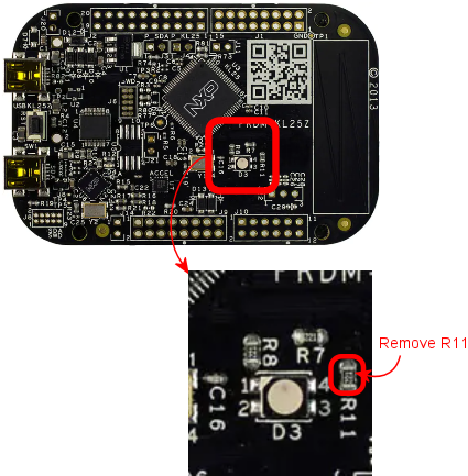

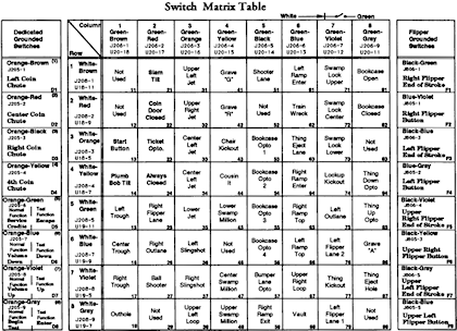
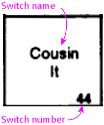
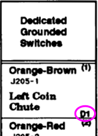
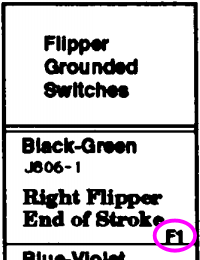
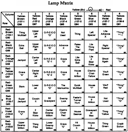
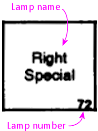
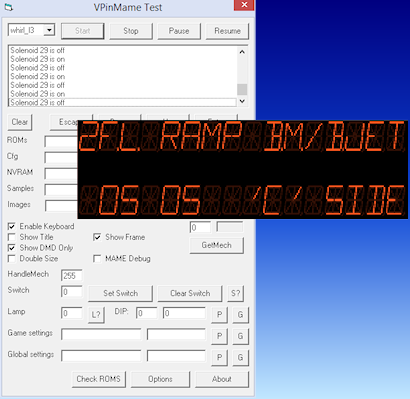
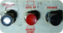 The operator controls on these machines consist of two buttons:
"AUTO/UP - MANUAL/DOWN" (7 in MAME) and "ADVANCE" (8 in MAME). The
START button (1 in MAME) on the front of the machine also gets
involved in places. (There's a third button, as you can see
in the photo, but its only function is to reset the high
scores. Why they dedicated a whole button to this, rather than
using it to make menu navigation easier, supports my belief
that the programmer had evil intent.)
The operator controls on these machines consist of two buttons:
"AUTO/UP - MANUAL/DOWN" (7 in MAME) and "ADVANCE" (8 in MAME). The
START button (1 in MAME) on the front of the machine also gets
involved in places. (There's a third button, as you can see
in the photo, but its only function is to reset the high
scores. Why they dedicated a whole button to this, rather than
using it to make menu navigation easier, supports my belief
that the programmer had evil intent.)
 The switch outputs on the board are labeled as follows: